Abstract
A novel method for preparation of DNA tubes using the DNA tile system with assistance of a four-way branched DNA-porphyrin connector is described. The detailed DNA tube structures were characterized by atomic force microscopy (AFM).
Keywords: DNA, nanostructure, nanotube, self-assembly, supramolecular chemistry
Programmable arrangement of molecular building blocks through the self-assembly process is one of the most fascinating challenges for creation of the nano-scale materials.[1–3] Because of the base-pairing system and well-defined periodic structure of double helical DNA, oligonucleotides are promising molecules for achieving desired structure formation and arrangements. Structurally controlled crossover DNA motifs have been used as building blocks for creating one- and multi-dimensional nanostructures.[4–7] Recently, utilizing these crossover DNA molecules, extended structures such as tube structures have been created.[8–10] Further extension of the design for desired DNA structures could be achieved by employing various chemically modified oligonucleotides.
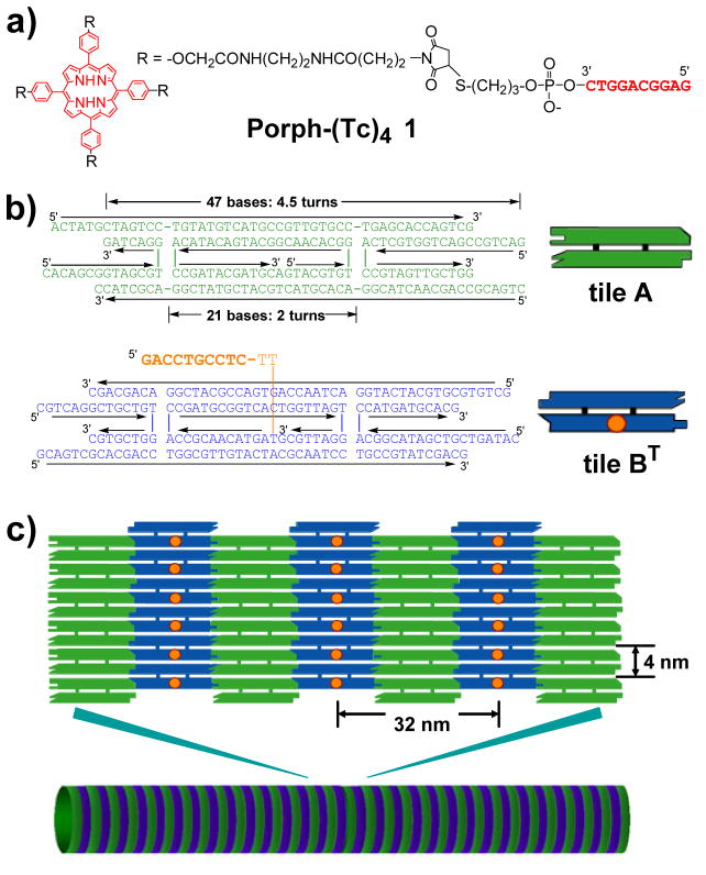
Here we report a novel method for preparation of structurally controlled DNA tube using DNA tile system[4–7] with assistance of a four-way branched DNA connector. Branched DNA can assemble multiple double helices by double helix formation.[11] In this study, we designed and synthesized a DNA-porphyrin connector Porph-(Tc)4 1 in which 10 mer DNA strands are connected to four spacers of a tetraphenylporphyrin derivative (Figure 1a). We also employed the DNA tile system which can assemble two planar DNA tiles (tile A and tile B) into two dimensional array structures using the geometry of 2.5 helical turns between two DNA tiles (Figure 1b and 1c).[4–7] In the B tile, the center strand of tile BT has a 12 mer extra single strand (T; tag strand) which has 10 bases as a recognition sequence for hybridization with a complementary DNA strand (Tc; complementary to the tag strand) and two additional thymidines as a linker. We planed to assemble the four BT tiles by using the DNA-porphyrin connector which captures and brings multiple BT tiles together by hybridizing with the extra tag strands of the BT tiles. Then the constrained four neighboring tiles by the DNA-porphyrin connector could induce the tube formation during assembly with the A tiles. The length of the DNA-porphyrin connector between the center of the porphyrin and the 5′-end of the DNA strand is 7–8 nm (Figure 1a), which could allow the alignment of the four shot axes of the B tiles side by side for the AB array formation.
Figure 1.
The DNA-porphyrin connector and DNA tiles system employed in the experiment. a) Structure of the DNA-porphyrin conjugate; Porph-(Tc)4 1. b) The sequences of DNA tile A (green) and BT (blue) which has an extra single strand (orange sequence). Orange dots on the tile B represent the extra single strand. c) Two-dimensional DNA array prepared from the tiles A and BT (top) and DNA tube structure (bottom).
Synthesis of DNA-porphyrin conjugate 1 was achieved by coupling of tetramaleimido-linked tetraphenylporphyrin with a 3′-thiol modified 10 mer DNA strand (Tc) which is complementary to the tag strand of the tile BT (Scheme S2). Ten DNA strands and Porph-(Tc)4 1 were mixed together and annealed from 95 °C to rt for 36 h in a buffer containing HEPES (pH 7.5), EDTA, and Mg2+.[12]
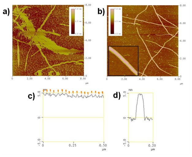
After complex formation, we observed the DNA nano-scale structures using atomic force microscopy (AFM) in solution.[12] In the case of annealing with tiles A and BT, two dimensional DNA arrays were obtained similar to those previously described using the A–B* array system (Figure 2a).[6–7] In contrast, by addition of 1/4 equivalent of Porph-(Tc)4 1 connector and annealing with the tiles A and BT, the large two dimensional structures disappeared and fiber-like structures were observed (Figure 2b), and their length reached over 20 μm. Cross-section analysis of the long axis of DNA fibers reveals that the periodic stripes are observed on the surface of the fiber (Figure 2c). The distance between two stripes was 29–34 nm, which corresponds to the total length of the long axis of the A and B tiles (32 nm) (Figure 1c). Therefore, these stripes originated from the extra strand of tile BT. In the case of the A-BT 2D array, only subtle stripes were observed as compared to the A-B* array described previously (Figure S4).[6–7] The B* tile has hairpins on the 2D-tile, which work as topological markers because of their orientation out of the plane of the tile.[6–7] In the A-BT array system employed here, the stripes were not observed clearly because the single strand attached to the B tile was flexible. This suggests that the strong stripe formation is induced by duplex formation between the tag strand of the tile BT and its complementary strand in the connector 1. The individual DNA fibers showed uniform width (ca. 55 nm) and height (5.2–5.6 nm) (Figure 2e), and the height of the stripes was 0.3–0.8 nm. The analysis results indicate that the height of the DNA structure is larger than two layers of double helices. According to the cross-section analysis of the higher-height area, the center of the top surface is slightly squashed by 0.2–0.3 nm as compared to both edges (Figure 2e).[13] From these observations, the DNA structures observed here exhibited the features of DNA tube structures as similar to the previous reports.[8,12–13] We conclude that the DNA structures obtained here are tube structures.
Figure 2.
AFM images of DNA structures. a) Annealing with tiles A and BT. b) Annealing with tiles A and BT, and Porph-(Tc)4 1. Inset: Expanded image of DNA structure prepared from the tiles A and BT, and 1. c) Section analysis of the long axis of the DNA structure in Figure b inset. Orange arrows represent peaks of the periodical stripes. d) Section analysis of the short axis of the DNA structure in Figure b inset. Image sizes, 8 × 8 μm2 (a and b); 500 × 500 nm2 (b inset).
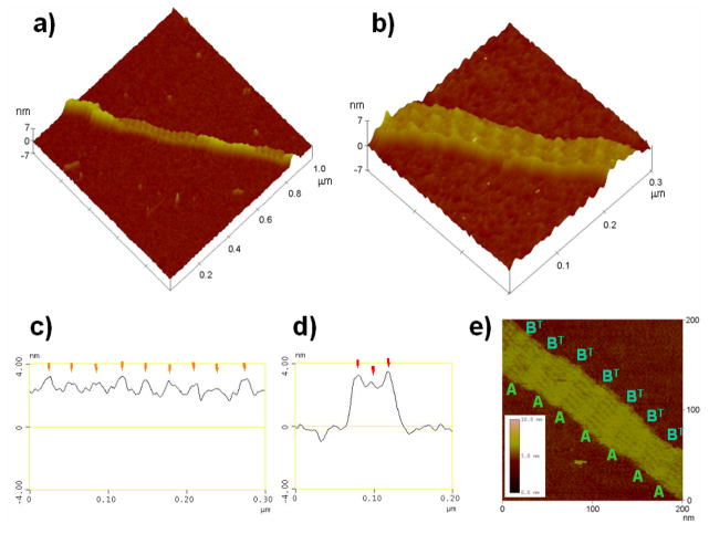
We also obtained DNA structures containing lower-height than the normal ones and these two structures were located on the same DNA fiber (Figure 3a). We noted that in the detailed structures of these lower-height DNA structures (Figure 3b), each stripe on the DNA surface has two or three blocks of dot-like structures, which is characterized by cross-section analysis of the stripes (Figure 3d). Cross-section analysis for the long axis revealed that each stripe was separated by 29–34 nm (Figure 3c), which corresponds to the length of the long axis of the AB-tiles as describe previously. The height of the surface of the lower-height structures was 2.7 nm (Figure 3d). The height of the stripes was 0.3–1.0 nm, which is comparable to the stripes of the normal structures shown in Figure 2. A high resolution AFM image of the DNA surface in the lower structure in a different area is shown in Figure 3e. Each stripe is separated and the individual A-tiles can be observed as same as those of the A-B* arrays. In this lower-height section, the visible part of the array contains seven A-tiles and a similar number of less well resolved BT-tiles as repeating units.
Figure 3.
AFM images of the DNA structures. a) Mixed area of normal and lower-height DNA structures. The image size is 1 × 1 μm2. b) Expanded image of the lower-height section. Image size, 300 × 300 nm2. Cross section analysis of the lower-height area in Figure 3b for the long (c) and short (d) axes. e) High resolution AFM image of the DNA nanostructure of the lower-height area. Image size, 200 × 200 nm2.
To examine the difference between the normal and lower-height structures, we analyzed the boundaries of these structures on the same fiber (Figure 3a), and two interesting features were observed. (1) The stripes in the normal and lower-height area are successive without any gap. (2) The height of lower-height DNA structures is clearly changed to almost half height of the normal ones, and the width of the short axis of the lower-height structures (ca. 65 nm) is always larger than that of the higher ones (ca.55 nm) on the successive DNA structures. From these observations, we also conclude that the lower-height areas on the DNA fibers are incomplete tubes with the height of single layer duplexes as similar results described previously. [8, 13]
Casual inspection of the AFM images gives the impression that the porphyrin connectors are in the outside of the tube structures. However, from thickness measurements, we cannot exclude the possibility that they are on the inside, the circumstance that is most likely to lead to tube formation. We estimated the complex formation process using the UV absorption change at 260 nm. The temperature of duplex formation of Porph-(Tc)4 1 with its complementary strand was 46 °C, which is slightly higher than the beginning temperature of the A-B array formation (40–45 °C). This indicates that the complex formation between 1 and four BT tiles occurs before the A-B array formation for the tube structures. The formation of DNA fiber structures depended on the stoichiometry between the tiles and Porph-(Tc)4 1. When 1/16 equivalent of 1 was added to the tiles A and BT, we obtained a mixture of fiber structures and usual two-dimensional arrays (Figure S7).
We have demonstrated the novel method for preparation of DNA tubes with the AB tile system and the four-way branched DNA connector which leads DNA arrays to DNA tube structures. The DNA-porphyrin connector clearly limited the extension to the short axis of the tile, while the long axis did not change as compared to that of the usual A-B tile system. We expect that the DNA tubes prepared using this method can be employed for nano-scale scaffolds to prepare structurally defined materials and devices.[13–14]
Acknowledgments
We thank Dr. Ruojie Sha (New York University) for assistance with the experiments. This work has been partly supported by a Grant-in-Aid for Scientific Research (Project 17105005, Priority Area (417), 21st Century COE Research, and others) from the Ministry of Education, Culture, Sports, Science and Technology (MEXT) of Japanese Government to ME and TM, as well as grants to NCS from the National Institute of General Medical Sciences, National Science Foundation, Office of Naval Research, the Army Research Office, and Nanoscience Technologies, Inc.
Contributor Information
Dr. Masayuki Endo, Email: endo@sanken.osaka-u.ac.jp, The Institute of Scientific and Industrial Research, Osaka University, 8-1 Mihogaoka, Ibaraki, Osaka 567-0047, Japan, Tel: +81-6-6879-8495; Fax: +81-6-6879-8499
Prof. Dr. Nadrian C. Seeman, Department of Chemistry, New York University, New York, NY 10003, USA
Prof. Dr. Tetsuro Majima, Email: majima@sanken.osaka-u.ac.jp, The Institute of Scientific and Industrial Research, Osaka University, 8-1 Mihogaoka, Ibaraki, Osaka 567-0047, Japan, Tel: +81-6-6879-8495; Fax: +81-6-6879-8499
References and Notes
- 1.a) Lehn J-M. Supramolecular Chemistry. VHC; Weinheim: 1995. [Google Scholar]; (b) Lehn JM. Chem Eur J. 2000;6:2097–2102. doi: 10.1002/1521-3765(20000616)6:12<2097::aid-chem2097>3.0.co;2-t. [DOI] [PubMed] [Google Scholar]
- 2.a) Hill DJ, Mio MJ, Prince RB, Hughes TS, Moore JS. Chem Rev. 2001;101:3893–4011. doi: 10.1021/cr990120t. [DOI] [PubMed] [Google Scholar]; b) Brunsveld L, Folmer BJB, Meijer EW, Sijbesma RP. Chem Rev. 2001;101:4071–4097. doi: 10.1021/cr990125q. [DOI] [PubMed] [Google Scholar]
- 3.a) Mirkin CA. Inorg Chem. 2000;39:2258–2272. doi: 10.1021/ic991123r. [DOI] [PubMed] [Google Scholar]; b) Niemeyer CM. Angew Chem Int Ed. 2001;40:4128–4158. doi: 10.1002/1521-3773(20011119)40:22<4128::AID-ANIE4128>3.0.CO;2-S. [DOI] [PubMed] [Google Scholar]
- 4.a) Seeman NC. Angew Chem Int Ed. 1998;37:3220–3238. doi: 10.1002/(SICI)1521-3773(19981217)37:23<3220::AID-ANIE3220>3.0.CO;2-C. [DOI] [PubMed] [Google Scholar]; b) Seeman NC. Biochemistry. 2003;42:7259–7269. doi: 10.1021/bi030079v. [DOI] [PubMed] [Google Scholar]
- 5.Fu TJ, Seeman NC. Biochemistry. 1993;32:3211–3220. doi: 10.1021/bi00064a003. [DOI] [PubMed] [Google Scholar]
- 6.Winfree E, Liu F, Wenzler LA, Seeman NC. Nature. 1998;394:539–544. doi: 10.1038/28998. [DOI] [PubMed] [Google Scholar]
- 7.Liu F, Sha R, Seeman NC. J Am Chem Soc. 1999;121:917–922. [Google Scholar]
- 8.Liu D, Park SH, Reif JH, Yan H. Proc Natl Acad Sci USA. 2004;101:717–722. doi: 10.1073/pnas.0305860101. [DOI] [PMC free article] [PubMed] [Google Scholar]
- 9.Mitchell JC, Harris JR, Malo J, Bath J, Turberfield AJ. J Am Chem Soc. 2004;126:16342–16343. doi: 10.1021/ja043890h. [DOI] [PubMed] [Google Scholar]
- 10.Rothemund PWK, Ekani-Nkodo A, Papadakis N, Kumar A, Fygenson DK, Winfree E. J Am Chem Soc. 2004;126:16344–16352. doi: 10.1021/ja044319l. [DOI] [PubMed] [Google Scholar]
- 11.a) Scheffler M, Dorenbeck A, Jordan S, Wüstefeld M, von Kiedrowski G. Angew Chem Int Ed. 1999;38:3311–3315. [PubMed] [Google Scholar]; b) Stewart KM, McLaughlin LW. J Am Chem Soc. 2004;126:2050–2057. doi: 10.1021/ja037424o. [DOI] [PubMed] [Google Scholar]; c) Stewart KM, Rojo J, McLaughlin LW. Angew Chem Int Ed. 2004;43:5808–5811. doi: 10.1002/anie.200460399. [DOI] [PubMed] [Google Scholar]
- 12.Complex formation was carried out in a 100 μL solution containing 0.5 μM of oligonucleotides (total 10 strands), 0.125 μM of Porph-(Tc)4 1, 10 mM HEPES (pH 7.5), 1 mM EDTA, and 5 mM Mg(OAc)2. Samples were annealed from 95 °C to rt over 36 h in a 2 L of water bath kept in a styrol box.[7] A sample (4 μL) was deposited on a freshly cleaved mica plate and left for 1 min to adsorb onto the surface. After addition of a 30 μL solution containing 10 mM HEPES (pH 7.5), 1 mM EDTA, and 5 mM Mg(OAc)2 in a fluid cell and another 30 μL of the same solution onto the AFM tip, images were acquired on a Digital Instruments NanoScope IV atomic force microscopy using tapping mode.
- 13.Yan H, Park SH, Finkelstein G, Reif JH, LaBean TH. Science. 2003;301:1882–1884. doi: 10.1126/science.1089389. [DOI] [PubMed] [Google Scholar]
- 14.Le JD, Pinto Y, Seeman NC, Musier-Forsyth K, Taton TA, Kiehl RA. Nano Lett. 2004;4:2343–2347. doi: 10.1021/nl0515495. [DOI] [PubMed] [Google Scholar]


