

Abstract
The current study presents a finite element model of mitral leaflet tissue, which incorporates the anisotropic material response and approximates the layered structure. First, continuum mechanics and the theory of layered composites are used to develop an analytical representation of membrane stress in the leaflet material. This is done with an existing anisotropic constitutive law from literature. Then, the concept is implemented in a finite element (FE) model by overlapping and merging two layers of transversely isotropic membrane elements in LS-DYNA, which homogenizes the response. The FE model is then used to simulate various biaxial extension tests and out-of-plane pressure loading. Both the analytical and FE model show good agreement with experimental biaxial extension data, and show good mutual agreement. This confirms that the layered composite approximation presented in the current study is able to capture the exponential stiffening seen in both the circumferential and radial directions of mitral leaflets.
Keywords: Finite element modeling, Mitral leaflet mechanics, Constitutive modeling
1 Introduction
The mitral apparatus comprises the valve annulus, chordae tendineae, and two leaflets, which are characterized by a layered, anisotropic structure. The fibrosa is the main load bearing layer of the leaflets, and consists of densely packed collagen that is oriented predominantly in the circumferential direction, relative to the valve annulus. The atrialis layer is composed of loosely organized collagen, elastin fibers, and contains proteoglycans and glycosaminoglycans [5, 9]. The collagen orientation is more variable in this layer, with angles that deviate from the circumferential direction [13]. Proteoglycans are present throughout the leaflet thickness but are the primary matrix component at the interface between the fibrosa and atrialis layers (spongiosa) [7]. The final layer is the ventricularis, which has a similar composition to the atrialis in terms of collagen and elastin fiber content [5, 9]. The relative thickness of each layer depends on the location in the mitral leaflet, for example near the annulus, the center, or at the free edge, and also varies depending on which leaflet is being investigated, i.e., posterior versus anterior. Kunzelman et al. [9] determined through histological studies of porcine leaflets that the fibrosa layer is roughly 55 % of the total thickness in the posterior leaflet, while in the anterior leaflet the fibrosa is roughly 70 % of the total thickness. This layered structure plays a key role in the deformation of the mitral valve leaflets during the cardiac cycle. Only recently has the layered structure been incorporated into an FE model, which was composed of solid elements [14].
Several studies have been performed in the areas of material testing and constitutive modeling of mitral leaflet tissue. Kunzelman and Cochran [8] performed uniaxial extension tests to quantify the stress–stretch relationship of porcine mitral valve tissue. May-Newman and Yin [13] performed biaxial extension tests on porcine mitral valve tissue, and then fit the stress–stretch data to a nonlinear hyperelastic constitutive law. Prot et al. [15] proposed a similar invariant-based constitutive law to represent mitral leaflet mechanics, which includes a Fung-like exponential term. It has been shown by Billiar and Sacks [1] that collagen fibers in the aortic valve exhibit splay in their orientation through the thickness. This was implemented in a finite element (FE) model of the mitral valve by Einstein et al. [4], and has been shown histologically in regions away from the fibrosal layer [13]. Both studies sought to incorporate this characteristic by integrating a distribution function of the collagen content. Recently, studies have been undertaken to investigate the possible role of contractile muscles cells in mitral valve mechanics [18]. It has been hypothesized that adding contraction during the systolic phase can eliminate non-physiological bulging that occurs in FE models. In general, it has been shown in literature that the radial and circumferential directions of the mitral leaflet exhibit the typical exponential stiffening seen in biological tissues, when exposed to extension testing. In addition, the circumferential direction is stiffer than the radial direction [13].
Several of the constitutive models for mitral leaflet tissue have been implemented as user-defined material subroutines in commercial FE codes, including Adina [19, 20], Abaqus [14, 15], and LS-DYNA [3, 4]. However, because these material models are not part of the standard FE code, they are not readily available for use. One of the goals in the present work is to develop a model of mitral leaflet tissue that can be implemented without the need for developing a user-defined material model. This is done by utilizing existing tools within the FE code.
In order to demonstrate this goal, the commercial FE code LS-DYNA is used. There is a soft tissue material model (material 91) implemented in the standard version of LS-DYNA [6], but it is not directly applicable for modeling mitral leaflet tissue, because it is unable to capture the exponential response exhibited in the radial direction. This limitation must be overcome in order to construct a FE model of leaflet tissue that incorporates the proper anisotropic structure. This is accomplished by utilizing composite theory, in conjunction with material 91, to overlap and merge membrane elements in the model. The overall response is essentially a weighted average of the contribution from each layer, rather than modeling discrete layers. The resulting analytical and numerical models are then fitted to experimental data. It should be noted that the approach outlined in this paper can be implemented with any commercial FE code that contains a membrane element formulation and a transversely isotropic material model, i.e., one that incorporates a single direction of fibers.
2 Methods
2.1 Continuum mechanics framework
In order to describe the modeling used in the present work, we briefly review some key continuum mechanics definitions. The deformation gradient is defined as,
| (1) |
where X denotes the position in the undeformed (reference) configuration and x denotes the position in the deformed configuration. The right Cauchy-Green deformation tensor is defined as,
| (2) |
and the principal invariants of C are defined as,
| (3a) |
| (3b) |
| (3c) |
where J is the Jacobian. Transverse isotropy is incorporated using the pseudo-invariant.
| (4) |
where a0 is a unit vector aligned with the fibers in the reference configuration and λf is the stretch along the fiber direction.
Quapp and Weiss [17] developed a transversely isotropic, hyperelastic, incompressible constitutive model to represent the pseudoelastic material behavior of ligament. This model is implemented in LS-DYNA as the soft tissue material model (material 91). For use in the present work, the strain energy function is taken to be,
| (5) |
where F1 represents the behavior of the matrix component of the tissue (Neo-Hookean model) and F2 represents the contribution from the fibers (Fung-type exponential). In the formulation developed by Quapp and Weiss [17], the tissue is assumed to have a single dominant fiber direction, with a soft response in the non-fiber directions.
The stress tensor can be written in terms of the strain energy function,
| (6) |
where S is the second Piola–Kirchhoff stress tensor. Using the chain rule to differentiate Eq. (6), the stress can be written in terms of the invariants of C,
| (7) |
Assuming that the fibers deform as material lines in the continuum, the fiber direction in the current configuration, a, can be written as
| (8) |
where a is a unit vector. By directly enforcing incompressibility, i.e. J = 1, the Cauchy stress (σ = J−1FSFT) can be written as,
| (9) |
where p is the hydrostatic pressure and B is the left Cauchy-Green deformation tensor. The material parameters are incorporated through the functions F1 and F2, such that
| (10a) |
| (10b) |
where C1, C3, and C4 are material constants. It should be noted that the parameter C2, which is associated with a Mooney-Rivlin material model, is not used in the present work.
2.2 Analytical layered composite modeling approach
In order to represent the response of the mitral leaflets as a layered structure, we employ theory from laminated fiberreinforced composites. The layered structure of the leaflets is characterized by a primary (stiff) support in the circumferential direction due to the dense collagen in the fibrosa layer, and a secondary support in the radial direction that is due to loosely organized collagen in the atrialis and ventricularis layers. Since the composition of the atrialis and ventricularis is similar, it is assumed that each has the same material response [9]. For this reason, the example described in the present work attempts to capture these two main characteristics in a two-layer composite. It is possible to extend the following approach to any number of layers, but for this preliminary study only two were employed.
The top and side view of a generic two-layered composite sheet, which is loaded uniformly at the edges, can be seen in Fig. 1. In a thin-layered composite, it can be assumed that the strain in each loading direction is constant at all points through the thickness, if the layers of the composite are perfectly bonded together [16]. In such cases, each layer carries a fraction of the total force. In a two-layered composite the total force is defined as the sum of the forces carried by each layer, such that P = P1 + P2, where P1 and P2 are the forces carried by layers 1 and 2, respectively. The total thickness can be written as t = t1 + t2, where t1 and t2 are the thickness of layers 1 and 2, respectively. The cross-sectional area for each layer is defined as A1 = t1w and A2 = t2w, where w is the width of the composite. Additionally, the composite acts as a membrane if there is no shear deformation out of the plane. The membrane stress in each loading direction can be written as σ = P/A = P=(tw). With the appropriate substitution, the total force can be rewritten as,
Fig. 1.

Top view of a generic composite of width w, which is loaded uniformly on each edge by a force P, as well as a side view of the composite with two distinct layers of thickness t1 and t2. Note that P is the total force acting along the edge face of the composite
| (11) |
where σ1 is the membrane stress in first layer and σ2 is the membrane stress in second layer, independent of direction. It can be inferred from Eq. (11) that the thickness ratios act as weighting functions for the stress in each layer, i.e., they scale the amount of stress that each layer contributes to the total membrane stress. Since the layer thickness varies between different leaflets, weight functions are used to represent the total stress in the most general form,
| (12) |
where and . It should be noted that this expression holds for any type of material model. In the present work, it is assumed that each layer is composed of the transversely isotropic material model described in the previous section, and each layer has a distinct fiber orientation.
In order to capture the exponential stiffening effect in both the circumferential and radial directions, the fibers in each layer were assigned angles based on histological measurements in literature [13]. The fiber angles were assumed to coincide with the collagen orientation in the fibrosa and atrialis/ventricularis layers, i.e., α1 = 0° and α1 = 35°, respectively, relative to the e1 direction. For generality, the fiber vectors can be written as,
| (13a) |
| (13b) |
where α1 is the fiber angle in the first layer and α2 is the angle in the second layer, as shown in Fig. 2a. To define the in-plane membrane stress, the following steps are taken:
Fig. 2.

a Generic fiber orientations relative to the e1 and e2 directions. b Construction of the two-layer finite element model. The fibers in the top layer are oriented in the circumferential (e1) direction and the fibers in the bottom layer are oriented at 35°, relative to the e1 direction. The two layers are merged together, such that the nodes are coincident and the in-plane strain is uniform through the thickness. The fibers are shown as white lines
Equations (10a, 10b) and (13a, 13b) are substituted into Eq. (9).
The result is then substituted into Eq. (12).
The components of stress are then calculated, i.e., σ11 = e1 · σe1.
Using the assumption of plane stress (since mitral tissue acts like a thin membrane), σ33 = 0. As a result, the pressure can be written as .
Finally, the membrane stress in the two-layered composite structure can be written as,
| (14a) |
| (14b) |
where σ11 and σ22 are the Cauchy stresses in the e1 and e2 directions, respectively; λ1, λ2, and λ3 are the principal stretches; λf1 and λf2 are the stretches in fiber direction 1 and 2, respectively; C3,1 and C4,1 are the fiber material constants in layer 1; and C3,2 and C4,2 are the fiber material constants in layer 2. Equation 14a, 14b represents the total membrane stress in each of the loading directions and is essentially a weighted average of the stress in each layer, just like composite theory. If one desires, can be replaced with , due to incompressibility.
2.3 Numerical implementation of the layered approach
The layered composite approach outlined in the previous section was implemented in LS-DYNA using two layers of bilinear membrane elements, which were assigned distinct fiber angles and properties using material 91 for each layer. The layersweremerged together (Fig. 2b), such that the nodes of the two membrane layers were assigned to be coincident, ensuring that in-plane strain was the same in overlapping elements, as assumed in composite theory. In the present study, each set of elements represented a fraction of the total thickness of the mitral leaflets and was assumed to act as a membrane using a single integration point through the thickness.
For the numerical implementation of material 91 in LSDYNA, the strain energy function is decoupled into the deviatoric and volumetric contributions [6]. This was accomplished using the deviatoric invariants, which are based on the multiplicative decomposition of the deformation gradient, . The strain energy function is given as,
| (15) |
where F̄1 and F̄2 represent the deviatoric contribution to the strain energy and represents the volumetric contribution. The parameter κ is a positive penalty parameter used to enforce near-incompressibility, and should be at least three orders of magnitude larger than C1. The membrane element implementation of material 91 utilizes a Belytschko-Tsay formulation [6]. The anisotropic material properties are associated with a local coordinate system that is attached to each element. The fiber angles are defined relative to the local x-axis.
2.4 Parameter fitting
Material parameters were determined by fitting the membrane stresses in the two loading directions, given by the analytical formulation in Eq. (14a, 14b), to several biaxial stretching experiments reported in May-Newman and Yin [13]. A Genetic Algorithm was employed to determine the optimal set of material parameters that minimize the difference between the predicted and experimental stress– stretch curves, i.e., minimize (R2 − 1) for each set of curves, where R2 is the coefficient of determination. A Genetic Algorithm is an intelligent searching technique that can be used to minimize an objective function without the need for taking the gradient, which makes the technique very versatile. Each optimization was conducted by successively refining the search area until the parameter values were unchanged. Details about the method can be found in the work by Zohdi [22]. The optimization was coded and analyzed in MATLAB (v7.0.1, Natick, MA). In the present study, the parameters were determined by simultaneously fitting Eq. (14a, 14b) to several loading cases, including equibiaxial, 2:1 off-biaxial [where the ratio of (λ1 − 1): (λ2 − 1) is held constant], and strip biaxial (where the radial direction is held constant at λ2 = 1.1, while the circumferential stretch is varied). This was done for both the anterior and posterior leaflets.
2.5 Numerical simulations
Two types of numerical simulations were conducted. First, biaxial stretch tests were simulated and compared to the analytical approach and experimental data [13]. The material parameters, which were determined by fitting the analytical formulation, were assigned as the parameters in the finite element model. A square sample of mitral leaflet was modeled using a single element for each layer, and then merging them together. The model was loaded using biaxial displacement boundary conditions in LS-DYNA, in order to generate stretches comparable to experimental testing [13]. The use of a single element for this type of numerical test has been used previously [15, 20]. The fibers angles were taken from May-Newman and Yin [13], which were also the angles used in the analytical formulation. The total thickness was taken to be 1 mm, based on the nominal value used in previous studies from the literature [15, 20]. The thickness ratios for the posterior leaflet were defined to be 55 % fibrosa layer and 45 % atrialis/ventricularis layers, while the anterior leaflet was defined to be 70 % fibrosa layer and 30 % atrialis/ventricularis layers [9]. In order to calculate the total membrane stress in each loading direction of the finite element model, the Cauchy stress in overlapping elements was multiplied by the thickness ratio and then summed together, as described in the previous section.
In the second set of simulations, out-of-plane pressure loading was applied to a spherical model with a radius of 10 mm and a total thickness of 0.5 mm, as described previously [15]. The mesh was constructed with 2,600 elements per layer (Fig. 3) and was assigned the material properties that were determined for the anterior leaflet. In addition, the fiber angles were assigned to be 0 and 35 degrees, relative to the circumferential direction, just like the biaxial simulations. The results were compared to a previous spherical model from the literature that employs an alternative constitutive law to represent the anterior mitral leaflet properties [15]. It should be noted that the constitutive model in Prot et al. [15] was also fitted to the same set of biaxial data [13], allowing for a direct comparison of the spherical model results in the current study.
Fig. 3.

View of the FE mesh used for the sphere geometry with outof- plane pressure loading. Point A is at the equator of the sphere, aligned with the circumferential direction, and point B is at the top of the sphere aligned with the radial direction
3 Results
The analytical stress–stretch relation, given in Eq. (14a, 14b), was fitted to experimental data for both the anterior and posterior leaflets [13]. The material parameters for each case were determined using a Genetic Algorithm to simultaneously fit three different loading conditions, and are shown in Table 1. In the anterior leaflet case the thickness ratios were w1 = 0.70 and w2 = 0.3, and for the posterior leaflet case the values were w1 = 0.55 and w2 = 0.45. It is well known that the anterior leaflet is stiffer than the posterior leaflet, as indicated by the increase in stress at lower values of stretch. The analytical approximation for the membrane stress was able to capture this trend with good agreement to the experimental data, as shown in Figs. 4 and 5.
Table 1.
Material properties determined by fitting Eq. (14a, 14b) to equibiaxial, 2:1 off-biaxial, and strip biaxial experimental data of the anterior and posterior mitral leaflet [13]
| C1 (kPa) | C3,1 (kPa) | C4,1 | C3,2 (kPa) | C4,2 | |
|---|---|---|---|---|---|
| Anterior | 0.126 | 0.011 | 52.97 | 0.028 | 48.65 |
| Posterior | 0.233 | 0.070 | 28.53 | 0.0075 | 44.97 |
Fig. 4.

Comparison of the analytical and numerical results to experimental data from the anterior leaflet of a mitral valve [13]. The three loading cases are a equibiaxial, b 2:1 off-biaxial, and c strip biaxial
Fig. 5.

Comparison of the analytical and numerical results to experimental data from the posterior leaflet of a mitral valve [13]. The three loading cases are a equibiaxial, b 2:1 off-biaxial, and c strip biaxial
The material parameters from the analytical solution (Table 1) were then used in the finite element implementation of a two-layer composite that was subjected to the three different biaxial stretch conditions mentioned previously. The parameter κ was adjusted to produce the best fit between the numerical and analytical results (Fig. 6). This approach was employed previously by Prot and Skallerud [14]. In the first set of simulations, κ was set equal to 102 kPa, which yielded reasonable results at low stretch values, but deviated once the stretch increased above 1.12. After several iterations, it was determined that a value of κ = 104 kPa produced the best result, when compared to the analytical fit of the experimental data. It can be seen in Figs. 4 and 5 that there is good agreement for all of the loading conditions.
Fig. 6.

Stress–stretch curves corresponding to the circumferential direction of the anterior leaflet equibiaxial loading case. Each curve shows the change due to increasing the bulk modulus
The pressure–displacement curves for the spherical model with out-of-plane loading are shown in Fig. 7. It can be seen that point B, which is located at the top of the sphere, deforms much more than point A. This is because the fibers are predominantly oriented in the circumferential direction, which restricts the deformation of point A. This causes the final deformed shape of the sphere to become more ellipsoidal, as seen in previous studies [15].
Fig. 7.
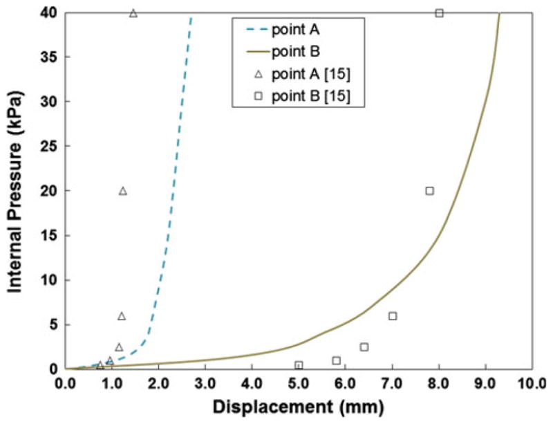
Pressure–displacement curves corresponding to points A and B on the sphere with out-of-plane loading. The lines represent the response from Eq. (14a, 14b) in the current study, while the markers correspond to the results of simulation in [15]
4 Discussion
Both the analytical and finite element model show good agreement with all three of the experimental biaxial stretch tests published by May-Newman and Yin [13], and show good mutual agreement (Figs. 4, 5). This confirms that the layered composite approach is able to capture the orthotropic exponential stiffening, seen in both the circumferential and radial directions of mitral leaflets. The FE simulations were performed using LS-DYNA, but the current approach could easily be implemented in any commercial code that has a membrane element formulation and a transversely isotropic material model. It is worth noting that both Adina and Abaqus contain built-in anisotropic material models.
It should be noted that the agreement between the analytical and experimental biaxial data was better for the anterior leaflet than the posterior leaflet. This is indicated by the fact that the nominal R2 value for the anterior loading cases was roughly 0.992, while the R2 value for the posterior loading cases was roughly 0.965. Other studies have performed parameter fitting analyses with mitral leaflet constitutive models, but have not quantified the accuracy of the fit [15, 19]. However, based on a visual inspection of those results it appears that the overall fit is good, with a better fit of the anterior results, similar to the current work.
The finite element implementation of the layered composite approach ran stably and maintained near-incompressibility during the simulations over a physiologically realistic range of stretch values. The value of κ was determined to be 104 kPa. However, this parameter has taken on different values in previous studies. In the work by Weinberg and Mofrad [20], κ was set to 105 kPa, whereas Prot and Skallerud [14] employed a value of 106 kPa. It appears that the value changes depending on the constitutive model and the FE formulation used to implement near-incompressibility. For example, the volumetric term in the current approach uses ln(J)2, whereas Weinberg and Mofrad employ(J − 1)2. A general approach to determine the value of κ is to simply adjust the value until there is good agreement between analytical and numerical stress–stretch curves.
In the out-of-plane loading case, there are differences between the previously published model [15] and the approach presented in the current study (Fig. 7). Some of these differences could be due to the mesh density used in each case, but are most likely due to differences in the material models themselves. Both pressure–displacement curves imply that the current approach is slightly stiffer during the initial inflation, when compared to the values from [15]. However, the response is less stiff after 10 kPa, i.e., the displacement is greater for the same value of pressure in the current model, when loaded normal to the plane. This latter trend was also seen in a comparison of the model proposed by Prot et al. [15] and that of May-New-man and Yin [13].
There are limitations to the proposed work. While the use of a composite layered approach allows for the calculation of total membrane stress, it does not yield information about stress in the individual layers. Due to the distinct structure of each layer, this could be an important factor that is not taken into account. The composite approach does a good job of modeling the orthotropic response of the mitral leaflets, as indicated by the curve fits that were conducted. However, the resulting stress–stretch relation contains five material parameters that must be determined. This is more than other models that have been proposed in the literature. For example, some only contain three parameters [13]. But, the advantage of the current approach is that one can use any transversely isotropic constitutive law to represent each layer in the composite approach. Thus, if a material model is available, in a different FE code, with fewer parameters, then the final resulting stress–stretch relation would be more compact. Material model 91 was selected in the current study because it contains an exponential term that acts in the fiber direction, which is similar to how mitral leaflets respond. The secondary fiber angle of 35° was selected because the value was taken near the center of the leaflet [13]. However, there may be variation in the fiber angles in this region, which could affect the material parameters determined in this study.
Finite element modeling of the mitral valve is becoming an integral part of investigations related to valvular disease and treatment strategies. Several studies have used FE models of the isolated mitral apparatus to evaluate the effects of mitral regurgitation and surgical interventions [2, 10, 11, 12]. Wenk et al. [21] developed an FE model of the LV, which included the mitral apparatus, in order to evaluate the effects of LV myocardial material properties on the level of mitral regurgitation. In conclusion, the modeling technique outlined in the current study will allow for further progression of mitral valve research, through the use of readily available FE computing tools.
Acknowledgments
This study was supported by NIH grants R01- HL-84431 (Dr. Ratcliffe), R01-HL-63348 (Dr. Ratcliffe), R01-HL- 77921 (Dr. Guccione), and R01-HL-86400 (Dr. Guccione). This support is gratefully acknowledged. We would like to thank Mike Burger and Nielen Stander at LSTC for their insights.
Contributor Information
Jonathan F. Wenk, Email: wenk@engr.uky.edu, Department of Mechanical Engineering, University of Kentucky, 269 Ralph G. Anderson Building, Lexington, KY 40506-0503, USA. Department of Surgery, University of Kentucky, Lexington, KY, USA.
Mark B. Ratcliffe, Department of Surgery, University of California, San Francisco, CA, USA. Department of Bioengineering, University of California, San Francisco, CA, USA. Department of Veterans Affairs Medical Center, San Francisco, CA, USA
Julius M. Guccione, Department of Surgery, University of California, San Francisco, CA, USA. Department of Bioengineering, University of California, San Francisco, CA, USA. Department of Veterans Affairs Medical Center, San Francisco, CA, USA
References
- 1.Billiar KL, Sacks MS. Biaxial mechanical properties of the native and glutaraldehyde-treated aortic valve cusp: part II—a structural constitutive model. J Biomech Eng. 2000;122(4):327–335. doi: 10.1115/1.1287158. [DOI] [PubMed] [Google Scholar]
- 2.Dal Pan F, Donzella G, Fucci C, Schreiber M. Structural effects of an innovative surgical technique to repair heart valve defects. J Biomech. 2005;38:2460–2471. doi: 10.1016/j.jbiomech.2004.10.005. [DOI] [PubMed] [Google Scholar]
- 3.Einstein D, Reinhall P, Nicosia M, Cochran R, Kunzelman K. Dynamic finite element implementation of nonlinear, anisotropic hyperelastic biological membranes. Comput Meth Biomech Biomed Eng. 2003;6(1):33–44. doi: 10.1080/1025584021000048983. [DOI] [PubMed] [Google Scholar]
- 4.Einstein DR, Kunzelman KS, Reinhall PG, Nicosia MA, Cochran RP. Haemodynamic determinants of the mitral valve closure sound: a finite element study. Med Biol Eng Comput. 2004;42(6):832–846. doi: 10.1007/BF02345218. [DOI] [PubMed] [Google Scholar]
- 5.Grande-Allen KJ, Liao J. The heterogeneous biomechanics and mechanobiology of the mitral valve: implications for tissue engineering. Curr Cardiol Rep. 2011;13:113–120. doi: 10.1007/s11886-010-0161-2. [DOI] [PMC free article] [PubMed] [Google Scholar]
- 6.Halquist JO. LS-DYNA theory manual. 2006 http://www.dynasupport.com/manuals.
- 7.Hinton RB, Yutzey KE. Heart valve structure and function in development and disease. Ann Rev Physiol. 2011;73:29–46. doi: 10.1146/annurev-physiol-012110-142145. [DOI] [PMC free article] [PubMed] [Google Scholar]
- 8.Kunzelman KS, Cochran RP. Stress/strain characteristics of porcine mitral valve tissue: parallel versus perpendicular collagen orientation. J Cardiac Surg. 1992;7(1):71–78. doi: 10.1111/j.1540-8191.1992.tb00777.x. [DOI] [PubMed] [Google Scholar]
- 9.Kunzelman KS, Cochran RP, Murphree SS, Ring WS, Verrier ED, Eberhart RC. Differential collagen distribution in the mitral valve and its influence on biomechanical behaviour. J Heart Valve Dis. 1993;2:236–244. [PubMed] [Google Scholar]
- 10.Kunzelman K, Reimink MS, Verrier ED, Cochran RP. Replacement of mitral valve posterior chordae tendineae with expanded polytetrafluoroethylene suture: a finite element study. J Cardiac Surg. 1996;11(2):136–145. doi: 10.1111/j.1540-8191.1996.tb00028.x. [DOI] [PubMed] [Google Scholar]
- 11.Kunzelman KS, Einstein DR, Cochran RP. Fluid-structure interaction models of the mitral valve: function in normal and pathological states. Philos Trans R Soc B. 2007;362:1393–1406. doi: 10.1098/rstb.2007.2123. [DOI] [PMC free article] [PubMed] [Google Scholar]
- 12.Maisano F, Redaelli A, Soncini M, Votta E, Arcobasso L, Alfieri O. An annular prosthesis for the treatment of functional mitral regurgitation: finite element model analysis of a dog bone-shaped ring prosthesis. Ann Thorac Surg. 2005;79(4):1268–1275. doi: 10.1016/j.athoracsur.2004.04.014. [DOI] [PubMed] [Google Scholar]
- 13.May-Newman K, Yin FCP. A constitutive law for mitral valve tissue. J Biomech Eng. 1998;120(1):38–47. doi: 10.1115/1.2834305. [DOI] [PubMed] [Google Scholar]
- 14.Prot V, Skallerud B. Nonlinear solid finite element analysis of mitral valves with heterogeneous leaflet layers. Comput Mech. 2009;43(3):353–368. [Google Scholar]
- 15.Prot V, Skallerud B, Holzapfel GA. Transversely isotropic membrane shells with application to mitral valve mechanics. Constitutive modelling and finite element implementation. Int J Numer Meth Eng. 2007;71(8):987–1008. [Google Scholar]
- 16.Qu J, Cherkaoui M. Fundamentals of micromechanics of solids. Wiley; Hoboken: 2006. pp. 226–240. [Google Scholar]
- 17.Quapp KM, Weiss JA. Material characterization of human medial collateral ligament. J Biomech Eng. 1998;120(6):757–763. doi: 10.1115/1.2834890. [DOI] [PubMed] [Google Scholar]
- 18.Skallerud B, Prot V, Nordrum IS. Modeling active muscle contraction in mitral valve leaflets during systole: a first approach. Biomech Model Mechanobiol. 2011;10:11–26. doi: 10.1007/s10237-010-0215-9. [DOI] [PubMed] [Google Scholar]
- 19.Weinberg EJ, Kaazempur-Mofrad MR. A large-strain finite element formulation for biological tissues with application to mitral valve leaflet tissue mechanics. J Biomech. 2006;39(8):1557–1561. doi: 10.1016/j.jbiomech.2005.04.020. [DOI] [PubMed] [Google Scholar]
- 20.Weinberg EJ, Mofrad MRK. A finite shell element for heart mitral valve leaflet mechanics, with large deformations and 3D constitutive material model. J Biomech. 2007;40(3):705–711. doi: 10.1016/j.jbiomech.2006.01.003. [DOI] [PubMed] [Google Scholar]
- 21.Wenk JF, Zhang Z, Cheng G, Malhotra D, Acevedo-Bolton G, Burger M, Suzuki T, Saloner DA, Wallace AW, Guccione JM, Ratcliffe MB. First finite element model of the left ventricle with mitral valve: insights into ischemic mitral regurgitation. Ann Thorac Surg. 2010;89(5):1546–1553. doi: 10.1016/j.athoracsur.2010.02.036. [DOI] [PMC free article] [PubMed] [Google Scholar]
- 22.Zohdi TI. Genetic design of solids possessing a random-particulate microstructure. Philos Trans R Soc London, Ser A. 2003;361(1806):1021–1043. doi: 10.1098/rsta.2003.1179. [DOI] [PubMed] [Google Scholar]