

Abstract
Radiofrequency shimming with multiple channel excitation has been proposed to increase the transverse magnetic field uniformity and reduce specific absorption rate at high magnetic field strengths (≥ 7 Tesla) where high-frequency effects can make traditional single channel volume coils unsuitable for transmission. In the case of deep anatomic regions and power-demanding pulse sequences, optimization of transmit efficiency may be a more critical requirement than homogeneity per se. This work introduces a novel method to maximize transmit efficiency using multiple channel excitation and radiofrequency shimming. Shimming weights are calculated in order to obtain the lowest possible net radiofrequency power deposition into the subject for a given transverse magnetic field strength. The method was demonstrated in imaging studies of articular cartilage of the hip joint at 7 Tesla. We show that the new radiofrequency shimming method can enable reduction in power deposition while maintaining an average flip angle or adiabatic condition in the hip cartilage. Building upon the improved shimming, we further show the signal-to-noise ratio in hip cartilage at 7 Tesla can be substantially greater than that at 3 Tesla, illustrating the potential benefits of high field hip imaging.
Keywords: RF Shimming, B1 Shimming, Adiabatic Excitation, RF Power Deposition, SAR, Ultra-High-Field MRI, Hip, Hip Articular Cartilage
INTRODUCTION
The promise of improved morphological and functional imaging due to higher signal-to-noise ratio (SNR) have motivated the pursuit of ultra-high field magnetic resonance (MR) imaging (≥ 7 Tesla (T)). However, ultra-high field MRI is challenging, due to inhomogeneities of the transverse radiofrequency (RF) magnetic field (B1+), which compromise image quality, and specific absorption rate (SAR) constraints, which limit the strength of MR excitation at depth.
RF shimming (1,2) and parallel excitation (3,4) techniques using multiple transmit channels have been shown to allow significant reductions in B1+ field inhomogeneities. While RF shimming has limited capability to provide homogeneous B1+ over large regions, local phase-only RF shimming (5) which aims at B1+ phase coherence/constructive interference in small target regions, such as the prostate, have been shown to provide reasonable homogeneity and increase in B1+ field for a given transmit RF power. Depending on the particular application in question, different RF shimming methods have been proposed which, for example target B1+ magnitude and phase homogeneity (1), target B1+ magnitude homogeneity without regard for B1+ phase (6), tradeoff B1+ homogeneity for SAR minimization (7–9), pursue B1+ homogeneity by sequential application of two different RF shim weights (10), or facilitate the adiabatic condition of the RF pulse (11,12).
In this paper a maximum efficiency RF shimming approach is presented, which, given any coil-subject setup, calculates a set of RF shim weights that maximizes B1+ strength for any given level of RF power deposition into the subject. Field interference is the fundamental principle underpinning multi-port or array coil transmission. While desirable B1+ interference patterns are sought after for managing the excitation profile (as is the case in shimming for B1+ homogeneity or in full-fledged parallel RF transmission), concomitant electric field interference impacts RF power deposition. The present approach, which not only accounts for transmit sensitivity patterns but also for subject-specific electric field interference effects on global SAR and net RF power, has a unique advantage over existing methods that aim at increasing power efficiency by performing guided manipulation of the B1+ field only.
The feasibility of the new RF shimming method was demonstrated in imaging studies of hip articular cartilage, an application that is clinically significant yet technically challenging. Accurate assessment of hip anatomy and function has become a critical concern in recent years, after it was shown that the success of surgical procedures aimed at delaying or preventing hip osteoarthritis by correcting the bony abnormalities associated with femoroacetabular impingement (13) depends on the absence of irreversible degenerative changes in the hip cartilage (14). However the evaluation of the hip cartilage is currently a challenge even at 3 T and normally requires administration of exogenous contrast agent to capture areas of abnormalities with sufficient contrast and SNR (15).
Maximum efficiency RF shimming can be an enabling technical solution to advance high field hip imaging and benefit clinical practice. Hip imaging represents an application that targets a deep anatomical region and demands good SNR. Conventional RF shimming at ultra high field tends to face difficulties managing RF power. Furthermore, as the thickness of the hip articular cartilage, which covers the femoral head and the acetabulum, ranges approximately from 1.5 to 5 mm (16), decreased power deposition could be leveraged to increase spatial resolution and/or SNR by allowing increases in the achievable flip angle and/or the number of refocusing pulses.
Following a description of the maximum efficiency RF shimming method, experimental calibration of the inputs for the proposed RF shimming method is explained. Using experimental power and B1+ map measurements, maximum efficiency RF shimming was compared with non-targeted unit RF shimming using different RF pulse types (sinc and adiabatic). In addition, simulations incorporating subject-specific calibration data, including individual channel B1+ maps and transmit power correlation matrix, were used to compare the proposed method with three existing RF shimming methods. Finally, in order to illustrate the gains at high field strength in anatomical regions of significant clinical interest, quantitative SNR comparisons in hip articular cartilage between 3 T and 7 T were conducted.
MATERIALS AND METHODS
Maximum Efficiency RF Shimming
RF shimming (1,2) was proposed to correct B1+ inhomogeneities by optimizing the relative amplitudes and phases of multiple transmit elements driven with a common RF waveform. Flexibility to control the relative amplitude and phase of the individual transmit elements can also be exploited to increase transmit efficiency. This section describes the maximum efficiency RF shimming method which aims to maximize B1+ strength for any given level of RF power deposition into the subject.
In order to obtain the complex-valued RF shim weights that correspond to the amplitude and phase modulation associated with maximum transmit efficiency, we use a transmit efficiency metric defined as B1+ magnitude squared per unit dissipated power, following earlier work by Zhu et al. (17). Using the superposition principle of linear systems, the net B1+ and electric field at each spatial location r and at each time t can be defined as
| [1] |
where N is the number of transmit elements, and the weights w(n) specify the amplitude and phase modulation of the driving RF current waveform in the nth channel of a transmit array. The complex-valued b(n)(r) and e(n)(r) represent, respectively, the B1+ and electric fields corresponding to unit weighting on the nth channel and zero weights on the others. Choosing an ROI, the values of B1+ at all M spatial locations included in the ROI can be combined in matrix form as where C is an M x N matrix with Cmn = b(n)(rm). The average B1+ squared in the ROI can be expressed as:
| [2] |
where the B1+ correlation matrix Γ = M−1CHC, and H denotes the conjugate transpose. Here, Γ is an N x N positive-definite complex Hermitian matrix.
The total RF power deposited by the parallel transmit array into the object at time t can be calculated by taking the following volume integral over the object and substituting the linear superposition of the electric fields from Eq. [1]:
| [3] |
where σ is the electrical conductivity, and Φ defines the N x N positive-definite complex Hermitian power correlation matrix whose (i, j)-th element is given by:
| [4] |
and * indicates complex conjugate.
A rapid calibration scheme to measure experimentally the entries of the coil- and subject-specific power correlation matrix in Eq. [4] has recently been described (18–20). Once Φ is known, RF power dissipation (Eq. [3]) (20) can be determined for any possible set of RF shimming weights w, allowing prediction of the global SAR consequences of any imaging sequence (9). For cases in which radiative losses and coil losses are significant, the resulting predicted power dissipation is an upper bound on overall RF power deposition in the subject; for the more common situation in which body losses are the dominant contribution, the predicted power dissipation more closely tracks global SAR in body tissues. Ref. (20) addresses these considerations in detail, as well as identifying potential improvements to the calibration process. The entries of the matrix C can be measured with any B1+ mapping technique, allowing the evaluation of Γ. Using the derived expressions for the average squared and the total RF power deposition for any RF shim weights w, the transmit efficiency metric can be defined as (17):
| [5] |
By streamlining the power calibration and B1+ mapping, the efficiency metric, η, can be practically evaluated in vivo. In practice, it is convenient to use units of μT squared per Watt. In the conventional single channel case, Γ and Φ reduce to scalars, and the metric captures B1+ squared per unit power, compatible with existing practice. In the multi-channel transmission case, different w’s correspond to different efficiency in general. In addition, given the bilinear form in both numerator and denominator, η is independent of any overall scale factor in the RF shimming weights (and therefore independent of any overall changes in transmit voltage).
Depending on the RF shimming coefficients, a given transmit array loaded with a given subject operates over a range of efficiencies. Searching for the RF shim weights that maximize η can be accomplished using various numerical optimization algorithms. However, it can be shown that calculating the maximum and minimum of η can be treated as a generalized eigenvalue problem which does not require a nonlinear search and guarantees the calculation of the global optimum. From the solution obtained with numerical calculations (for example with the Matlab function eig(Γ,Φ)), the largest eigenvalue and its corresponding eigenvector represent the maximum transmit efficiency and the maximum efficiency RF shim weights, w, respectively. Calculated maximum efficiency RF shim weights can be used in experiments to obtain the highest possible transmit efficiency for the given coil-patient configuration.
System Hardware and RF Coil Array
We evaluated the benefits of maximum efficiency RF shimming at 7 T, targeting hip imaging as an exemplary application. Experiments were performed on a whole body 7 T scanner (Magnetom, Siemens Medical Solutions, Erlangen, Germany) equipped with an eight-channel parallel transmit system (1kW peak power per transmit channel) and a gradient system capable of achieving peak gradient strength of 40 mT/m and a slew rate of 150 T/m/s. A 10-channel transmit/receive modular array (21) (Fig. 1a and 1c) consisting of five loop/stripline modules was used for RF excitation and reception. Loop coils were 8 × 20 cm2 with a solid copper shield 2 cm above the loop conductors to reduce radiation loss and coupling to neighboring coils and undesired anatomy such as the arms. The loops were tuned to 297.2 MHz using 16 distributed capacitors of approximately 16 pF. Striplines with 15 cm length and 2 × 3 × 15 cm3 Teflon dielectric were tuned using two capacitors of approximately 4.3 pF at opposing ends of the stripline. The striplines were centered with respect to the loop coils (Fig. 1b) such that their arrangement provided a naturally decoupled loop/stripline module similar to that described in Ref. (22). Both loops and striplines were capacitively matched to 50 Ω while loaded with a body-size agar phantom with uniform electrical properties of average human muscle at 297.2 MHz (εr ≈ 58, σ ≈ 0.77 S/m.). The array of loop/stripline modules was placed around the phantom or human torso with two posterior, one anterior and two lateral modules. The four loops closest to the targeted ROI (inside modules 1–4 in Fig. 1c) were used for RF transmission and reception, while the remaining 6 elements (loop inside module 5 and striplines inside modules 1–5) were used for RF reception only.
Figure 1.

a: Cross-sectional schematic of the coil and phantom setup. b: Photograph of a loop/stripline module. The conductor layout of the active element of the stripline and loop can be seen. c: Photograph of the 7 T experimental setup with a molded human phantom. Loop/stripline coil modules indicated by numbers 1–5 were used in hip experiments and the remaining modules were removed.
In order to evaluate the maximum efficiency RF shimming approach in terms of RF power reduction per B1+ squared, forward and reflected power readings were obtained from four channels via an RF switch (Dual 16 × 1 MUX, National Instruments, Austin, TX, USA) with a power sensor (NRP-Z11, Rhode & Schwarz, Munich, Germany) connected to directional couplers (C8705, Werlatone, New York) located at the penetration panel.
A 3T MRI scanner (Verio, Siemens Medical Solutions, Erlangen, Germany) equipped with a gradient system capable of achieving peak gradient strength of 40 mT/m and a slew rate of 150 T/m/s was used to image the hip of the same volunteers, and the SNR in the hip region was compared with that achieved using maximum efficiency RF shimming at 7T. The body coil was used for RF excitation and a 32-element cardiac coil array (Invivo, Orlando, FL) was placed around the pelvis for signal reception at 3T.
RF Shimming Experiments
The use of local transmit coils called for RF power limits to restrict possible tissue heating caused by the induced electric fields. To predict the spatial positions with the greatest electric fields, a finite difference time domain (FDTD) (Computer Simulation Technology, CST, Darmstadt, Germany), simulation (2 mm3 spatial resolution) was performed in which a loop coil representative of that used in the experiments was positioned adjacent to a uniform elliptical cylindrical phantom whose size and electrical properties were similar to the human torso and muscle, respectively (major diameter = 47.2 cm, minor diameter = 24.7 cm, electrical conductivity = 0.77 S/m, and dielectric constant = 58). To experimentally determine the safe operating limit of a single coil, the temperature of a 3.6 kg lamb slab was recorded using fluoroptic temperature probes (Luxtron M3300, Lumasense Technologies, Santa Clara, CA, USA) during RF irradiation. The fluoroptic probes were inserted approximately 5 mm into the lamb at four locations, including those with maximal electric fields according to the FDTD simulation; 1) coil drivepoint, 2) capacitor opposite the drivepoint, 3) capacitor midway along the side conductor, and 4) center of coil. Distance from the coil conductor to the lamb was approximately 2 cm. RF power was delivered to the coil for 10 min while the time-averaged (10 s) power was monitored by vendor-provided hardware. Following RF irradiation, temperature monitoring was continued for 2 mins to assess heat diffusion from locations adjacent to the temperature probes. No temperature increase was observed during the post-RF period. Assuming a linear relationship between RF irradiation and the rate of temperature change, the safe operating limit was defined as the 10 s time-averaged power input necessary to produce a 1°C temperature increase during a 10 min RF irradiation period. For a single coil, the total power limit was hence determined to be 10W. In the parallel transmit experiments, power limits were applied using a conservative criteria that assumed the worst-case scenario in which electric-fields due to individual transmit elements add constructively. Since four transmit loops were used in the present study, this approach limited the individual input power to 16 times less than the limit for a single loop (0.625W). In addition, 10 s and 6 min average RF power was monitored for each channel in real time.
Calculation of the maximum efficiency RF weights requires B1+ profiles for each transmitter along with the power correlation matrix. B1+ mapping was performed following the method described in Ref. (23) by performing two separate measurements using selective excitation of all channels without magnetization preparation and with a saturation pulse on one channel at a time to produce spatial-dependent B1+ map of the channel. B1+ magnitude maps, Fig. 2c, in an axial plane were obtained with sinc saturation pulses followed by a spoiled turbo fast low-angle shot (FLASH) imaging acquisition with selective excitation from all channels. Additional turbo FLASH imaging, using one coil for excitation at a time, were used to calculate relative B1+ phase distribution for different coils (Fig. 2d). Relevant imaging parameters used for B1+ mapping were: field of view (FOV) = 360 × 360 mm2, echo time (TE) = 1.97 ms, acquisition matrix = 128 × 128, TR = 3 s, saturation thickness = 10 mm, and slice thickness = 8 mm. Total acquisition time for B1+ maps in all four channels was 27 s. An ROI over the hip articular cartilage was defined on one of the images (Fig. 2b) and the corresponding Γ-matrix (Fig. 2e) was calculated using the individual coil B1+ profiles.
Figure 2.

Steps required for the calculation of the maximum efficiency RF shimming weights. a: Axial GRE image of one volunteer with the approximate stripline/loop coil module locations overlaid in red (transmit/receive loops and receive-only striplines) and green (receive-only loops and striplines). b: Zoomed GRE image with the target hip cartilage ROI (red) for maximum efficiency optimization. c: B1+ amplitude maps for each transmit loop. d: B1+ phase maps for each transmit loop. e: Γ-matrix calculated using the B1+ maps in the ROI. f: Calibrated power correlation matrix, Φ, measured using the forward and reflected power measurements of the system.
The subject-specific power correlation matrix Φ (Fig. 2f) was estimated from measurements of the individual channel forward and reflected power, using the power sensors connected to the directional couplers, associated with a set of calibration RF pulses (18–20). The net power measurements (forward minus reflected) during each predefined calibration pulse allows a set of linear equations resembling Eq. [3] to be assembled and solved, using the predefined values of w as known coefficients and assigning entries of Φ as unknowns. The calibrated Φ-matrix, the Γ-matrix and the ROI were used to calculate the maximum efficiency RF shim weights for the hip articular cartilage, following the procedure described in an earlier section.
Because experimental evaluation of several shim methods in the same volunteer would require excessive examination time, we used experimentally acquired B1+ maps and the calibrated Φ-matrix as simulation inputs for the offline comparison of four RF shimming strategies: the proposed maximum efficiency RF shimming, non-targeted unit RF shimming, local phase matching RF shimming, and uniformity-targeted RF shimming. The non-targeted unit RF shimming delivers RF with unit amplitude and zero phase offset to all transmit channels. Local phase matching (5) aims to increase the constructive B1+ interference in the target ROI by adjusting the transmit phase offset between each transmit channel. Uniformity-targeted RF shimming (1) aims to increase B1+ homogeneity inside the ROI by adjusting the relative transmit amplitude and phase to each channel through a least-squares solution.
In addition to the comparison of different RF shimming strategies in simulations, net average power deposition and flip angle maps were experimentally measured to compare the transmit efficiency achieved with the maximum efficiency RF shimming to that achieved with non-targeted unit RF shimming. The flip angle distribution resulting from both RF shimming methods, with acquisition matrix 256 × 256, was measured using the method detailed above with saturation pulses played simultaneously on all transmit channels. High resolution axial spoiled gradient echo (GRE) images of the hip region were acquired with maximum efficiency and non-targeted unit RF shimming using the following parameters: acquisition matrix = 512 × 512, spatial resolution 0.7 × 0.7 × 2 mm3, TE/TR = 4.73/400 ms, FOV = 360 × 360 mm2, bandwidth (BW) = 300 Hz/pixel, and acquisition time 210 s. Additionally, net average power deposition was measured using power sensors during GRE image acquisition.
Four volunteers (three men and one woman; age = 37.5 ± 9.2 years) were imaged in an axial plane through the left hip articular cartilage. Volunteer imaging was performed with protocols approved by the New York University School of Medicine Institutional Review Board, and written informed consent was obtained from volunteers.
Maximum efficiency RF shimming does not inherently increase B1+ homogeneity within the selected ROI. However as shown before, adequate B1+ homogeneity can be achieved in a small ROI, such as the prostate (5). On the other hand, a special class of RF pulses, such as the adiabatic pulse, inherently improve flip angle uniformity. A drawback of adiabatic pulses is the high RF power deposition required to satisfy the adiabatic condition at every voxel within the ROI. Since maximum efficiency RF shimming aims to maximize B1+ field while minimizing the power deposition, adiabatic pulses could benefit from the proposed RF shimming method. We tested this hypothesis both in simulation and in experiments for an adiabatic half passage (AHP) RF pulse (24). Experimentally measured individual channel B1+ profiles (Fig. 2c and d) and an AHP RF pulse of length 10.24 ms were used in spinor-domain Bloch simulations (25) to calculate the flip angle distribution. For the maximum efficiency shim and the non-targeted unit shim, the adiabatic condition at the position in the ROI with the weakest B1+ was determined by calculating the frequency response of the AHP RF pulse over a range of transmit voltages using Bloch simulations; the adiabatic condition at this position was satisfied when the z-component of magnetization at zero frequency was approximately zero and not affected by further transmit voltage increase. Net power deposition of AHP RF pulses with maximum efficiency shim and non-targeted unit shim was measured with the transmit voltage for each shim set such that the AHP RF pulse satisfied the adiabatic condition at all locations within the ROI. Flip angle distributions of the AHP RF pulses with maximum efficiency shim and non-targeted unit shim were measured using the technique described earlier for B1+ map acquisition (specifically, AHP RF pulses were played as saturation pulses followed by a turbo FLASH acquisition). In order to examine the off-resonance effect on AHP RF pulse, off-resonance maps were calculated from individual receive coils using the three point “Dixon method” that decomposes fat, water, and off-resonance through a least-squares calculation with complex gradient echo images at TE = 4.08, 4.42, and 4.76 ms (26). A combined off-resonance map was formed by weighting the contribution of each coil by the square of its signal intensity. The combined off resonance map was smoothed using a median filter with 5 × 5 kernel size.
SNR comparison
The SNR in the hip articular cartilage achieved with maximum efficiency RF shimming at 7 T was compared with that achieved at 3 T. High resolution spoiled axial GRE images of the hip region were acquired with low flip angles at both 3 T and 7 T, using the parameters given in the previous subsection. Due to different sample T1 in each magnet, low flip angle excitation was utilized to avoid magnetization saturation effects that would complicate SNR analysis. Noise data were acquired with zero transmit voltage and used to compute the noise covariance matrix of the receive coils. The GRE images and the noise covariance matrix were used to generate SNR maps following a method by Kellman and McVeigh (27).
Flip angle maps of the GRE acquisitions, with acquisition matrix 256 × 256, were obtained using the flip angle mapping protocol explained in the previous section. As the flip angle mapping algorithm is more prone to error at low flip angles, the flip angle maps were acquired with higher transmit voltages than those used in the GRE acquisitions. The acquired flip angle map was then scaled by the ratio of GRE transmit voltage to flip angle mapping transmit voltage. The scaled flip angle maps were interpolated to a matrix size of 512 × 512 to match the matrix size of the GRE acquisition. For fair comparison between 3 T and 7 T, we removed the effect of spatial flip angle variations by normalizing the SNR maps with the sine of the flip angle at each voxel. Three of the four volunteers were imaged at both 3 T and 7 T for SNR comparison.
RESULTS
Representative 7T axial GRE images with non-targeted unit RF shimming and maximum efficiency RF shimming for volunteer 1 are shown in Figures 3a and 3b, respectively. Non-targeted unit RF shimming resulted in B1+ inhomogeneity and large signal intensity variations in the hip region and a local signal drop indicated by the arrow in Fig 3c. The maximum efficiency RF shimming, with a targeted ROI covering the left hip articular cartilage (Fig. 2b), resulted in improved homogeneity in the hip region (Fig. 3d) and ~2.4 times increase in transmit efficiency, as calculated with Eq. [5]. In achieving similar average flip angles over the ROI in the cases of unit RF shimming (flip angle 27.6° ± 12.4°) and maximum efficiency RF shimming (flip angle 25.3° ± 12.1°), respectively, the net average energy deposition were measured to be 155 W and 58.8 W.
Figure 3.

Representative 7 T axial GRE images of volunteer 1, acquired with non-targeted unit RF shimming (a) and maximum efficiency RF shimming (b). Zoomed images of the hip articular cartilage show that low signal caused by destructive RF interference with non-targeted unit RF shimming (arrow in c) is restored using maximum efficiency RF shimming (d).
Transmit efficiency comparisons between different RF shimming methods are summarized in Table 1. For all volunteers, maximum efficiency RF shimming provided the highest transmit efficiency. Among the RF shimming methods, local phase matching provided the second highest transmit efficiency (on average 22% lower than that of the maximum efficiency method). In all volunteers, uniformity RF shimming resulted in lowest transmit efficiency. This could be attributed to the method’s priority of increasing B1+ uniformity over increasing average B1+. The RF power deposition benefit using maximum efficiency RF shimming compared to non-targeted unit RF shimming for all volunteers is shown on the last row of Table 1. Table 2 shows that in imaging experiments the net RF power deposition with maximum efficiency shim weights was on average 39% lower than that required to achieve similar flip angles with the non-targeted unit RF shim. The experimentally quantified RF power deposition benefit of using maximum efficiency RF shimming was in good agreement with the RF power deposition benefit quantified with simulations (last rows of Table 1 and 2). Calculated maximum efficiency RF shim weights varied substantially among the volunteers due to differences in body composition and size (Table 3).
Table 1.
Comparison of four RF shimming methods in simulations based on experimentally acquired transmit sensitivity and power correlation data: A: Non-targeted Unit RF shimming, B: Maximum Efficiency RF Shimming, C: Local phase matching RF shimming from Ref. (5), and D: Uniformity RF Shimming from Ref. (1). The RF power deposition benefit of using maximum efficiency RF shimming versus non-targeted unit RF shimming was calculated by comparing estimated power depositions per average unit squared flip angles.
| Shim Method | VOLUNTEER 1 | VOLUNTEER 2 | VOLUNTEER 3 | VOLUNTEER 4 | ||||||||||||
|---|---|---|---|---|---|---|---|---|---|---|---|---|---|---|---|---|
|
| ||||||||||||||||
| A | B | C | D | A | B | C | D | A | B | C | D | A | B | C | D | |
|
| ||||||||||||||||
| Flip Angle | 45.9 ± 14.3 | 40.0 ± 11.2 | 44.1 ± 11.2 | 17.8 ± 4.1 | 27.0 ± 7.6 | 23.4 ± 5.2 | 30.7 ± 6.4 | 9.0 ± 2.6 | 28.0 ± 19.4 | 23.9 ± 15.1 | 30.8 ± 20.5 | 7.6 ± 4.8 | 41.8 ± 12.0 | 34.5 ± 9.4 | 46.5 ± 13.9 | 13.2 ± 3.3 |
| Estimated Power (W) | 231.3 | 73.9 | 218.5 | 50.5 | 148.8 | 76.3 | 151.5 | 1.8 | 147.7 | 80.2 | 147.7 | 44.1 | 285.3 | 138.2 | 274.7 | 134.5 |
| Efficiency (η) | 9.97 | 23.34 | 9.46 | 6.58 | 5.27 | 7.51 | 6.51 | 1.78 | 7.83 | 9.96 | 9.23 | 1.83 | 6.62 | 9.22 | 8.57 | 2.08 |
| RF Power Deposition Benefit | 58% | 32% | 26% | 29% | ||||||||||||
Table 2.
Experimentally measured net power deposition and corresponding flip angle with non-targeted unit RF shimming and maximum efficiency RF shimming. Experiments using non-targeted unit RF shimming are denoted by A, and experiments using maximum efficiency RF shim weights are denoted by B. The RF power deposition benefit of using maximum efficiency RF shimming versus non-targeted unit RF shimming was calculated by comparing average net power depositions per average unit squared flip angles.
| Shim Method | Volunteer 1*
|
Volunteer 2
|
Volunteer 3
|
Volunteer 4
|
||||
|---|---|---|---|---|---|---|---|---|
| A
|
B
|
A
|
B
|
A
|
B
|
A
|
B
|
|
| Flip Angle | 27.6° ± 12.4° | 25.3° ± 12.1° | 6.3° ± 2.3° | 5.8° ± 2.2° | 4.3° ± 2.6° | 3.8° ± 2.8° | 6.9° ± 3.2° | 5.9° ± 2.6° |
| Net Power Deposition (W) | 155.33 | 58.85 | 5.28 | 2.74 | 6.80 | 3.69 | 18.10 | 8.76 |
| RF Power Deposition Benefit | 55% | 39% | 30% | 33% | ||||
GRE images and power measurements were obtained with higher flip angles compared to other volunteers
Table 3.
Calculated maximum efficiency RF shimming weights and measured individual anatomical dimensions for all volunteers.
| Transmit Coil Number | Body Dimensions (cm)* | |||||||||||
|---|---|---|---|---|---|---|---|---|---|---|---|---|
| 1 | 2 | 3 | 4 | |||||||||
| ||w|| |
 w w |
||w|| |
w |
||w|| |
w |
||w|| |
w |
A to C | P to C | L to C | R | |
| Volunteer 1 | 1 | 216.3° | 0.44 | 31.3° | 0.45 | 0.6° | 0.22 | 0° | 7.1 | 10.8 | 7.6 | 2.1 |
| Volunteer 2 | 0.76 | 273.4° | 0.71 | 17.7° | 1 | 342.7° | 0.36 | 0° | 7.6 | 9.6 | 8.9 | 2.5 |
| Volunteer 3 | 1 | 316.0° | 0.5 | 45.2° | 0.77 | 345.6° | 0.57 | 0° | 8.9 | 12.1 | 12.6 | 2.0 |
| Volunteer 4 | 1 | 15.9° | 0.45 | 92.1° | 0.67 | 348.1° | 0.61 | 0° | 7.7 | 12.1 | 12.3 | 2.2 |
Anterior (A), posterior (P), left (L), center of femoral head (C), and radius of femoral head (R).
The power deposition and flip angle distribution of an AHP RF pulse with maximum efficiency RF shim and non-targeted unit RF shim weights were assessed on volunteer 2. The maximum power required to meet the adiabatic condition at points inside the ROI with the weakest B1+ distribution was 411 W for maximum efficiency shim and 789 W non-targeted unit RF shim. Both shims resulted in a maximum of 2.31 μT instantaneous B1+ field in the weakest B1+ location. Bloch simulations of AHP RF pulses with the specified voltages resulted in a mean of 1% ± 3% z-magnetization, which corresponded to remarkably uniform flip angle distribution of 89.4° ± 1.7°. Flip angle distributions for maximum efficiency RF shim and non-targeted unit shim in the ROI are shown for Bloch simulations (Fig. 4c and 4d) and experiments (Fig. 4e and 4f). Whereas the Bloch simulation resulted in approximately uniform 90° flip angle, experimental flip angle maps show increased deviation in some locations which appear to correspond to locations with high main magnetic field gradients (Fig. 4h). This was confirmed in additional Bloch simulations that incorporated the off-resonance maps. The AHP pulse provided a clear improvement in B1+ uniformity over standard sinc excitation pulses (Figures 4a and 4b).
Figure 4.
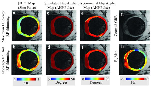
B1+ maps with (top row) and without (bottom row) maximum efficiency RF shimming. AHP pulses provided improved flip angle uniformity (columns two and three) over standard sinc pulses (column one) in the hip articular cartilage. h is the measured off resonance map.
Figure 5 shows GRE images of volunteer 4 at 7 T and 3 T (Fig. 5a and 5b) with flip angles (Fig. 5c and 5d) of 5.7° ± 2.6° and 9.7° ± 1.2° in the hip cartilage, respectively. Quantitative SNR maps of acquired GRE images are shown in Figures 5e and 5f. Figures 5e and 5f clearly show the actual SNR benefits of moving to higher field strength. Despite the lower flip angles at 7 T (Fig. 5c) compared to 3T (Fig. 5d), the average SNR was greater: 8.3 ± 4.9 at 7 T versus 6.9 ± 2.8 at 3 T (Fig. 5e and 5f). After dividing the SNR maps by the sine of the flip angle at each voxel, the normalized SNR was 43.4 ± 18.2 at 3 T and 83.5 ± 38.7 at 7 T. Averaged over all volunteers, 7 T normalized SNR was 133% greater than that at 3 T (Table 4).
Figure 5.

Axial GRE images (top row) and zoomed flip angle (middle row) and SNR maps (third row) from volunteer 4 at 7T (left column) and 3T (right column).
Table 4.
SNR results in the hip articular cartilage of three volunteers at 3 T and 7 T.
| Volunteer 2
|
Volunteer 3
|
Volunteer 4
|
||||
|---|---|---|---|---|---|---|
| 3 T
|
7 T
|
3 T
|
7 T
|
3 T
|
7 T
|
|
| Flip Angle | 9.6° ± 0.9° | 4.9° ± 1.9° | 10.2° ± 1.4° | 4.1° ± 2.5° | 9.7° ± 1.2° | 5.7° ± 2.6° |
| SNR | 8.8 ± 3 | 10.7 ± 5.9 | 6.0 ± 2.2 | 7.2 ± 3.4 | 6.9 ± 2.8 | 8.3 ± 4.9 |
| Normalized SNR | 53.4±20.1 | 124.5±52.8 | 34.6 ± 13.8 | 96.9 ± 51.9 | 43.4 ± 18.2 | 83.5 ± 38.7 |
| Normalized SNR gain at 7T | 2.30 | 2.77 | 1.92 | |||
DISCUSSION
In this work, we have demonstrated a maximum efficiency RF shimming method that finds the lowest possible net RF power deposition into the subject for a given flip angle inside the ROI. The proposed RF shimming method calculates optimal shim weights which increase transmit efficiency by utilizing in vivo calibrated predictions of the net RF power deposition along with B1+ field maps. Previous RF shimming methods (5,12) only utilize B1+ constructive interference without accounting for electrical field interference effects or power deposition. In addition, the transmit efficiency metric defined in Eq. [5] enabled the global optimum RF shimming weights to be efficiently calculated, without the need for computationally intensive nonlinear search algorithms (11,28).
The proposed RF shimming method was compared in simulations using experimental B1+ maps and power correlation matrices with three different RF shimming methods: a) non-targeted unit RF shimming; b) uniformity-targeted RF shimming (1), which has been used to address the challenge of signal inhomogeneity that has hindered ultra-high-field imaging; and c) local phase matching RF shimming (5), which has been found to perform effectively in FDTD simulations (28). The simulations showed maximum efficiency RF shimming increased the transmit efficiency compared to other methods by including calibrated subject-specific RF power deposition predictions in RF shimming calculations. Some of the simulations were further corroborated by imaging experiments, which confirmed the validness of the comparison (last rows of Tables 1 and 2). In addition to the global RF power deposition behavior documented here, local SAR properties of the proposed method should be analyzed and compared with other RF shimming methods. However, for such a comparison, full knowledge of actual electric field information inside the subject is required. In future work, FDTD simulations can be used for such comparisons, since determining the actual electric field inside the subject is not yet feasible.
Hip imaging at 7 T was chosen as a representative application to demonstrate maximum efficiency RF shimming. In fact, imaging the hip joint is challenging due to its deep anatomical location, which requires large transmit voltages and results in severe B1+ inhomogeneities at high field strength. In our volunteer experiments, power measurements for sinc and AHP RF pulses in axial GRE acquisitions confirmed up to 50% decreases in RF power deposition while maintaining average flip angle distributions. This suggests that SAR-intensive pulse sequences, such as turbo spin echo (commonly used at lower magnetic field strengths for clinical hip imaging due to high SNR and contrast-to-noise ratio), may become feasible at 7T using multiple-coil transmission with maximum efficiency RF shimming. Our results show that the flip angle-normalized SNR in the hip articular cartilage was on average 2.3 times greater at 7 T than at 3 T. Furthermore, we showed that optimizing RF power deposition in a ROI tend to reduce B1+ inhomogeneities within it. One limitation of our SNR comparison study is the difference in receive coil sensitivities at 7 T and 3 T due to variation in coil size and structure. However, the hip lies at a similar depth (5 to 12 cm from the body surface) as the heart, suggesting that the cardiac array used at 3 T may serve as a reasonable SNR benchmark.
In this study, GRE pulse sequences were used for the SNR comparison because they are less SAR-intensive and therefore facilitated a comparison between 3T and 7T with our existing transmit hardware setup and safety limits. While GRE images are not widely used for clinical morphological assessment of the hip articular cartilage, they are employed for biochemical assessment in which T1 and T2* are measured (29,30). In these applications, which could be facilitated at 7 T using maximum efficiency RF shimming, improved SNR would result in more reliable T1 or T2* quantification, or could be traded off for increased spatial resolution, which is essential to resolve the thin layer of articular cartilage in the hip joint (16).
In summary, the maximum efficiency RF shimming method utilizes both electric and magnetic field measurements corresponding to the in situ transmit array and is subject to promptly calculate transmit shim weights that minimize the power required for a given flip angle. An accompanying benefit of the proposed shim method was that it provided reasonable flip angle uniformity in a clinically relevant ROI. The shim method was successfully demonstrated in experimental 7 T MRI of the hip articular cartilage, confirming the present method’s potential to outperform other shim methods in terms of efficiency.
Acknowledgments
The authors thank Dr. Hans-Peter Fautz from Siemens Medical Solutions in Erlangen, Germany for collaboration on the flip angle mapping sequence. Dr. Graham Wiggins is acknowledged for discussions on SNR comparison. The authors thank Dr. Bei Zhang for her help in FDTD simulations, Kellyanne Mcgorty for her help on sequence protocols and Dr. Assaf Tal for useful discussions on adiabatic RF pulses.
This work was supported in part by NIH grants R01-EB011551 and R01-EB000447.
References
- 1.Hoult DI, Phil D. Sensitivity and power deposition in a high-field imaging experiment. J Magn Reson Imaging. 2000;12(1):46–67. doi: 10.1002/1522-2586(200007)12:1<46::aid-jmri6>3.0.co;2-d. [DOI] [PubMed] [Google Scholar]
- 2.Ibrahim TS, Lee R, Baertlein BA, Abduljalil AM, Zhu H, Robitaille PM. Effect of RF coil excitation on field inhomogeneity at ultra high fields: a field optimized TEM resonator. Magn Reson Imaging. 2001;19(10):1339–1347. doi: 10.1016/s0730-725x(01)00404-0. [DOI] [PubMed] [Google Scholar]
- 3.Katscher U, Bornert P, Leussler C, van den Brink JS. Transmit SENSE. Magn Reson Med. 2003;49(1):144–150. doi: 10.1002/mrm.10353. [DOI] [PubMed] [Google Scholar]
- 4.Zhu Y. Parallel excitation with an array of transmit coils. Magn Reson Med. 2004;51(4):775–784. doi: 10.1002/mrm.20011. [DOI] [PubMed] [Google Scholar]
- 5.Metzger GJ, Snyder C, Akgun C, Vaughan T, Ugurbil K, Moortele P-FVd. Local B1+ shimming for prostate imaging with transceiver arrays at 7T based on subject-dependent transmit phase measurements. Magnetic Resonance in Medicine. 2008;59(2):396–409. doi: 10.1002/mrm.21476. [DOI] [PMC free article] [PubMed] [Google Scholar]
- 6.Mao W, Smith MB, Collins CM. Exploring the limits of RF shimming for high-field MRI of the human head. Magnetic Resonance in Medicine. 2006;56(4):918–922. doi: 10.1002/mrm.21013. [DOI] [PMC free article] [PubMed] [Google Scholar]
- 7.Bob van den B, Cornelis ATVdB, Lambertus WB, Jan JWL. 7 T body MRI: B1 shimming with simultaneous SAR reduction. Physics in Medicine and Biology. 2007;(17):5429. doi: 10.1088/0031-9155/52/17/022. [DOI] [PubMed] [Google Scholar]
- 8.Lattanzi R, Sodickson DK, Grant AK, Zhu Y. Electrodynamic constraints on homogeneity and radiofrequency power deposition in multiple coil excitations. Magn Reson Med. 2009;61(2):315–334. doi: 10.1002/mrm.21782. [DOI] [PMC free article] [PubMed] [Google Scholar]
- 9.Deniz CM, Alon L, Brown R, Daniel KS, Zhu Y. Specific Absorption Rate Benefits of Including Measured Electric Field Interactions in Parallel Excitation Pulse Design. Magnetic Resonance in Medicine. 2012;(67):164–174. doi: 10.1002/mrm.23004. [DOI] [PMC free article] [PubMed] [Google Scholar]
- 10.Orzada S, Maderwald S, Poser BA, Bitz AK, Quick HH, Ladd ME. RF excitation using time interleaved acquisition of modes (TIAMO) to address B1 inhomogeneity in high-field MRI. Magnetic Resonance in Medicine. 2010;64(2):327–333. doi: 10.1002/mrm.22527. [DOI] [PubMed] [Google Scholar]
- 11.Balchandani P, Khalighi MM, Hsieh SS, Setsompop K, Pauly J, Spielman D. Adiabatic B1 Shimming Algorithm for Multiple Channel Transmit at 7T. Proceedings of the 19th Scientific Meeting, ISMRM; Montreal. 2011. p. 2907. [Google Scholar]
- 12.Setsompop K, Wald LL, Adalsteinsson E. Reduced-Voltage RF Shimming for Adiabatic Pulse Design in Parallel Transmission. Proceedings of the 15th Scientific Meeting, ISMRM; Berlin. 2007. p. 1687. [Google Scholar]
- 13.Ganz R, Parvizi J, Beck M, Leunig M, Nötzli H, Siebenrock KA. Femoroacetabular Impingement: A Cause for Osteoarthritis of the Hip. Clinical Orthopaedics and Related Research. 2003;417:112–120. doi: 10.1097/01.blo.0000096804.78689.c2. [DOI] [PubMed] [Google Scholar]
- 14.Beck M, Leunig M, Parvizi J, Boutier V, Wyss D, Ganz R. Anterior Femoroacetabular Impingement: Part II. Midterm Results of Surgical Treatment Clinical Orthopaedics and Related Research. 2004;418:67–73. [PubMed] [Google Scholar]
- 15.Kassarjian A. Hip MR Arthrography and Femoroacetabular Impingement. Semin Musculoskelet Radiol. 2006;10(03):208, 219. doi: 10.1055/s-2006-957174. [DOI] [PubMed] [Google Scholar]
- 16.Mechlenburg I, Nyengaard JR, Gelineck J, Soballe K. Cartilage thickness in the hip joint measured by MRI and stereology – a methodological study. Osteoarthritis and Cartilage. 2007;15(4):366–371. doi: 10.1016/j.joca.2006.10.005. [DOI] [PubMed] [Google Scholar]
- 17.Zhu Y, Deniz CM, Alon L, Fautz H-P, Sodickson DK. Undestanding Parallel Transmit Array Efficiency. Stockholm: 2010. p. 1518. [Google Scholar]
- 18.Zhu Y. In Vivo RF Power and SAR Calibration for Multi-Port RF Transmission. Proceedings of the 17th Scientific Meeting, ISMRM; Honolulu. 2009. p. 2585. [Google Scholar]
- 19.Alon L, Deniz CM, Lattanzi R, Wiggins G, Brown R, Sodickson DK, Zhu Y. An Automated Method for Subject Specific Global SAR Prediction in Parallel Transmission. Proceedings of the 18th Scientific Meeting, ISMRM; Stockholm. 2010. p. 780. [Google Scholar]
- 20.Zhu Y, Alon L, Deniz CM, Brown R, Sodickson DK. System and SAR Characterization in Parallel RF Transmission. Magnetic Resonance in Medicine. doi: 10.1002/mrm.23126. in press. [DOI] [PMC free article] [PubMed] [Google Scholar]
- 21.Brown R, Stoeckel B, Sodickson DK, Wiggins G. Investigation of Element Designs and Construction of a Reconfigurable 8 Channel Tx, 16 Channel Rx Torso Array for 7T. Stockholm: 2010. p. 3807. [Google Scholar]
- 22.Kumar A, Bottomley P. Optimized quadrature surface coil designs. Magnetic Resonance Materials in Physics, Biology and Medicine. 2008;21(1):41–52. doi: 10.1007/s10334-007-0090-2. [DOI] [PMC free article] [PubMed] [Google Scholar]
- 23.Fautz HP, Vogel M, Gross P, Kerr A, Zhu Y. B1 Mapping of Coil Arrays for Parallel Transmission. Proceedings of the 16th Scientific Meeting, ISMRM; Toronto. 2008. p. 1247. [Google Scholar]
- 24.Garwood M, DelaBarre L. The Return of the Frequency Sweep: Designing Adiabatic Pulses for Contemporary NMR. Journal of Magnetic Resonance. 2001;153(2):155–177. doi: 10.1006/jmre.2001.2340. [DOI] [PubMed] [Google Scholar]
- 25.Pauly J, Le Roux P, Nishimura D, Macovski A. Parameter relations for the Shinnar-Le Roux selective excitation pulse design algorithm. IEEE Trans Med Imaging. 1991;10(1):53–65. doi: 10.1109/42.75611. [DOI] [PubMed] [Google Scholar]
- 26.Reeder SB, Wen Z, Yu H, Pineda AR, Gold GE, Markl M, Pelc NJ. Multicoil Dixon chemical species separation with an iterative least-squares estimation method. Magnetic Resonance in Medicine. 2004;51(1):35–45. doi: 10.1002/mrm.10675. [DOI] [PubMed] [Google Scholar]
- 27.Kellman P, McVeigh ER. Image reconstruction in SNR units: A general method for SNR measurement†. Magnetic Resonance in Medicine. 2005;54(6):1439–1447. doi: 10.1002/mrm.20713. [DOI] [PMC free article] [PubMed] [Google Scholar]
- 28.van den Bergen B, van den Berg CAT, Klomp DWJ, Lagendijk JJW. SAR and power implications of different RF shimming strategies in the pelvis for 7T MRI. Journal of Magnetic Resonance Imaging. 2009;30(1):194–202. doi: 10.1002/jmri.21806. [DOI] [PubMed] [Google Scholar]
- 29.Bittersohl B, Hosalkar HS, Hughes T, Kim Y-J, Werlen S, Siebenrock KA, Mamisch TC. Feasibility of T2* mapping for the evaluation of hip joint cartilage at 1.5T using a three-dimensional (3D), gradient-echo (GRE) sequence: A prospective study. Magnetic Resonance in Medicine. 2009;62(4):896–901. doi: 10.1002/mrm.22096. [DOI] [PubMed] [Google Scholar]
- 30.Sur S, Mamisch TC, Hughes T, Kim Y-J. High resolution fast T1 mapping technique for dGEMRIC. Journal of Magnetic Resonance Imaging. 2009;30(4):896–900. doi: 10.1002/jmri.21869. [DOI] [PubMed] [Google Scholar]