Abstract
Purpose
Standard instrumentation tries to reproduce mechanical axes based on mechanical alignment (MA) guides. A kinematic alignment (KA) technique derives its plan from pre-operative MRI-measurements. This matched-pair cadaveric study compared the resulting postoperative alignments.
Methods
A prospective series of 12 torsos were acquired for a total of 24 limb specimens including intact pelvises, femoral heads, knees, and ankles.The cadavers received MRI scans to manufacture the kinematic alignment cutting guides. Two investigating surgeons performed total knee arthroplasties on randomly chosen sides using MA instruments. On the contralateral sides, KA cutting guides were used. A navigation system was used to measure final alignment.
Results
The overall alignment showed no significant differences between the systems. In the MA group the differences between the planned and the final implantation regarding overall limb alignment ranged between 0.2° and 6.2°. In the KA group the differences between the planned and final implantation regarding overall limb alignment ranged between 0.3° and 9.1°. The differences of the deviation from plan for overall limb alignment showed no significant differences between the methods.
Conclusions
The different alignment strategies resulted in variations of the combinations of the three-dimensional component position on the femur and the tibia. However, the legs were aligned within comparable range for both chosen techniques.
Introduction
Neutral axial alignment is a traditional target for total knee arthroplasty (TKA). This alignment is generally achieved by using mechanical axis (MA) guidance tools that help the surgeons to place cutting jigs in order to achieve precise cuts on the tibia and the femur that result in the desired alignment. Obviously, there is a range of error associated with the use of such extra-medullary and intra-medullary guidance devices [1]. In order to reduce the range of error, navigation systems have been introduced that have been shown to narrow the margin of error, but have not lead to significantly improved clinical outcomes [2–5].
Recently, a new paradigm of jig placement has been introduced: kinematic alignment (KA). This technique requires pre-operative three-dimensional scans of the bone and cartilage surface of femur and tibia. Subsequently, patient specific three dimensionally shaped cuttings blocks can be produced for the distal femoral and proximal tibial cuts. The goal of KA is to place the implant along the patient’s premorbid joint line. The KA concept is based on the work of authors like Eckhoff, Hollister and Coughlin [6–10].
While this new alignment (KA) concept might promise better clinical results, it is important to compare it to the alignment achieved by the traditional mechanical alignment (MA) technique. Therefore, this cadaver study was performed in order to compare the alignment range of the KA technique to the conventional MA technique.
Materials and methods
Twelve eviscerated torsos of fresh frozen human cadavers were acquired, resulting in 24 limb specimen with intact pelvises, femoral heads, knees and ankles. Of those cadavers, five were male and seven female. All of the cadavers were Caucasian. The average age at the time of death was 76.4 (range, 61 to 91), and their average weight was 58.4 kg (range, 38.6 to 97.5). All cadavers underwent pre-operative MRI scans in which the legs were placed in neutral position with straight knees. Prior to the MRI scan of the knee, an MRI scout was taken of all limbs. From this scout, the mechanical axis of the femur, the tibia and the overall limb alignment were measured by identifying the center of the head, the center of the distal femur, the tibial plateau and the ankle, as well as the knee joint line in the coronal plane.
Pre-operative planning and jig production
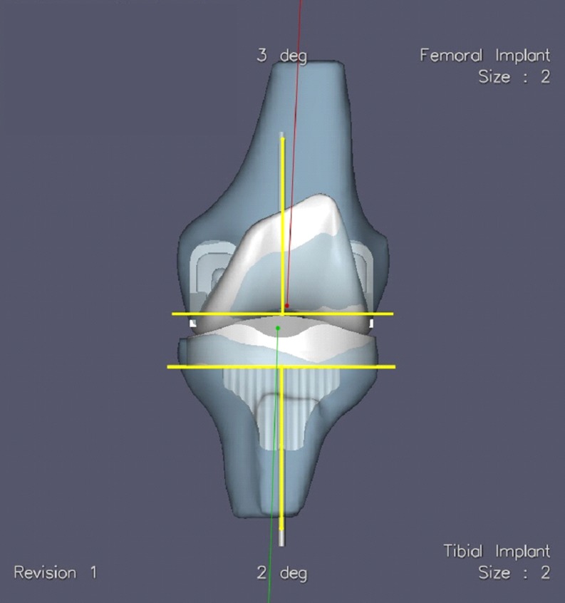
The study was designed as a matched pair study. For each cadaver torso, the left or the right knee was randomly chosen for either group 1 (conventional – MA) or group 2 (kinematic – KA). In the MA group, a standard cruciate retaining Triathlon® total knee (Stryker Orthopaedics, Mahwah, NJ) replacement with mechanical alignment guides was performed according to the manufacturer’s suggested technique. These knees underwent no further pre-operative planning. The goal for axial alignment for this group was defined as 0° varus / valgus limb alignment (neutral mechanical axis). For the MA group, intra-medullary alignment was used for the femur and extra-medullary alignment for the tibia. Femoral rotation was defined by posterior referencing set to 3° of external rotation to the posterior condyles, while rotation on the tibia was set to medial 1/3 of tibial tuberosity. For the KA group, the MRI scan was send to OtisMed (Almeda, CA, a subsidiary of Stryker Orthopaedics, Mahwah, NJ, USA). According to their internal kinematic alignment planning, which is not disclosed to the user in detail, a virtual implantation of a Triathlon® knee was performed. Customized jigs were produced according to this plan and were provided for the surgery. The plan not only set the orientation of the device, but also suggested appropriate sizes for the femoral and tibial components as well as the thickness of the polyethylene insert (see Fig. 1).
Fig. 1.
The KA surgical plan. Yellow lines represent the resection and perpendicular for the femur and tibia. Red is the mechanical axis of the femur. The green line is the mechanical axis of the tibia
Cadaver surgery
All surgeries were performed by two of the authors (DC, GD), both of whom performed 12 surgeries on six cadavers. Neither surgeon had any experience with the KA technique prior to this investigation, but underwent instructions for its use while at the lab. The six cadavers were randomly allocated to the surgeons. All cadavers were placed on a standard operating table in supine position. Prior to surgery, all cadavers were supplied with knee and femoral tracker pins for the Stryker Knee Navigation System (Stryker Leibinger, Freiburg, Germany), running the Stryker Knee Navigation Software 4.0. A pre-operative registration procedure was performed, and pre-operative registration data was recorded for each cadaver by one of the authors (GD).
A median parapatellar approach was used for exposure. For the MA knees, the surgery was performed using an extra-medullary alignment guide for the tibia and an intra-medullary alignment guide for the femur [11]. After placement of the jigs, the distal femoral cut and the proximal tibial cut were performed. Afterwards, the navigation resection probe was used to measure the orientation of the tibial and femoral cut and the resulting overall limb alignment.
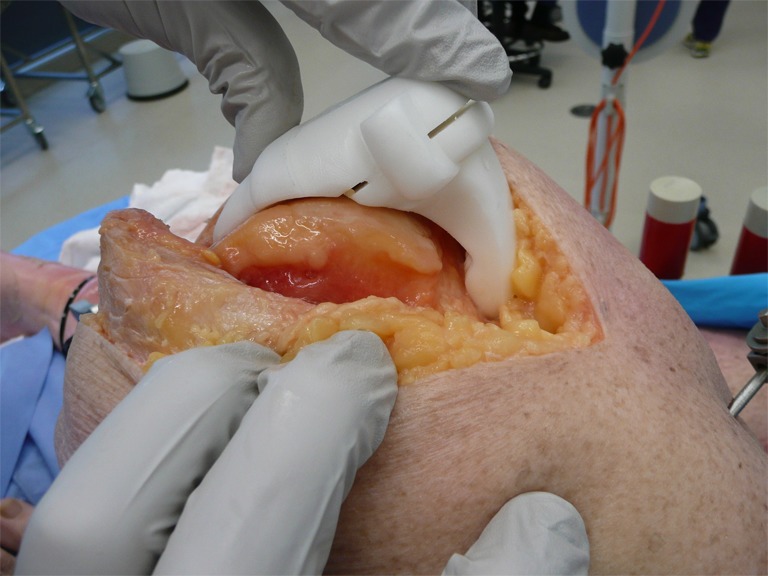
The distal femoral cuts and the proximal tibial cut for the KA knees were performed with the use of the customized jigs. Those jigs were placed on the femur and the tibia, respectively (see Fig. 2), according to the Triathlon® Knee System with OtisMed® ShapeMatch® technology technical manual [12].
Fig. 2.

The femoral jig in place
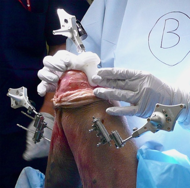
The orientation of the cuts was evaluated with the navigation system (Fig. 3).
Fig. 3.
Navigational measurement set-up
Consecutively, the procedure was continued in the same way for both groups by performing the keel preparation for the tibia and the surface cuts (4-in-1 block) for the femur. The final Triathlon implants were eventually placed with the use of Simplex™ cement (Stryker, Mahwah NJ). After final implantation, the resection probe of the navigation system was used to measure the varus /valgus orientation of the tibial as well as the femoral component.
We compared varus/valgus, tibial slope, rotation and flexion extension of the femur measured with the navigation system for the matched pairs. Additionally, we compared the varus/valgus orientation of the cuts with the pre-operative plan to calculate the deviation from the plan for both groups.
Statistical methods
SPSS 17.0 (IBM, Armonk, NY) was used for the statistical analysis. P-values of 0.05 or lower were considered statistically significant. Unmodified Kolmogorov-Smirnov goodness-of-fit tests were used to test for the distribution of the variables. Since the left and right knees came in pairs from the same cadaver, the analysis had to be perceived as a matched pair design, which lead to the selection of non-parametric Wilcoxon rank-sum tests for the method comparison.
Results
Table 1 shows the demographic data of the specimens. The pre-operatively measured varus/valgus axis of the knee compared well between the left and the right side.
Table 1.
Demographic data of the 12 cadavers
| Mean | SD | Min | Max | |
|---|---|---|---|---|
| Age | 76 | 9.75 | 61 | 91 |
| Weight (kg) | 58.4 | 20.5 | 38.6 | 97.5 |
All specimens in the sample were Caucasians of which ten were male and 14 female.
The Kolmogorov–Smirnov goodness-of-fit tests did not return any statistically significant deviations from normal, with p-values ranging from 0.409 to 1.000 for MA and 0.094 to 0.990 for KA.
Deviation from pre-operative plan
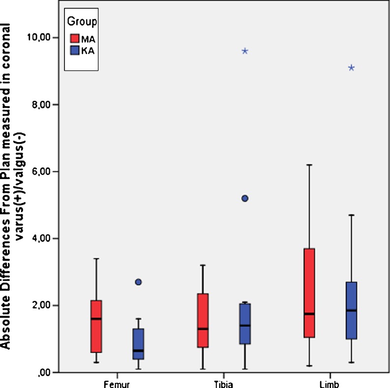
Both MA and KA methods produced comparable differences in varus(+)/valgus(−) from the pre-operative plan for femur (p = 0.126), tibia (p = 0.583) and limb alignment (p = 0.956). See Table 2 and Fig. 4.
Table 2.
Absolute differences from plan for femur, tibia and overall limb alignment measured as varus(+)/valgus(−) with 95 % confidence intervals (CI95) of the mean differences
| MA | KA | |||||||||
|---|---|---|---|---|---|---|---|---|---|---|
| Mean | SD | Min | Max | CI95 | Mean | SD | Min | Max | CI95 | |
| Femur | 1.52 | 1.04 | 0.30 | 3.40 | 0.85–2.18 | 0.90 | 0.74 | 0.10 | 2.70 | 0.43–1.37 |
| Tibia | 1.52 | 1.06 | 0.10 | 3.20 | 0.84–2.19 | 2.26 | 2.65 | 0.10 | 9.60 | 0.58–3.94 |
| Limb | 2.35 | 1.93 | 0.20 | 6.20 | 1.12–3.58 | 2.44 | 2.42 | 0.30 | 9.10 | 0.90–3.98 |
Fig. 4.
Absolute differences from plan in varus(+)/valgus(-) between MA and KA method for femur, tibia and overall limb. The rectangular boxes represent the inter-quartile ranges (25th to 75th percentile). Outliers (between 1.5 to 3 inter-quartile ranges away from the upper/lower limits of the box) are marked as circles, extreme values (more than three inter-quartile ranges away from the upper/lower limits of the box) as stars
Alignment
There was no statistically significant difference between the two groups in overall post-operative limb alignment concerning varus/valgus (p = 0.108). Table 3
Table 3.
Cut orientation by group for overall limb and individual femur and tibia resections, including p-values
| MA | KA | ||||||
|---|---|---|---|---|---|---|---|
| N | Mean | SD | N | Mean | SD | p | |
| Overall limb | |||||||
| Var(+)/Val(-) | 12 | 1.20 | 2.86 | 12 | −0.87 | 3.18 | 0.108 |
| Femur | |||||||
| Var(+)/Val(-) | 12 | −0.12 | 1.89 | 12 | −2.52 | 2.10 | 0.010 |
| Flex(+)/Ext(-) | 12 | 1.13 | 2.07 | 12 | 5.15 | 3.20 | 0.012 |
| Rot. Ext(+)/Int(-) | 12 | 0.11 | 6.39 | 12 | −2.28 | 3.81 | 0.388 |
| Tibia | |||||||
| Var(+)/Val(-) | 12 | 1.32 | 1.32 | 12 | 1.64 | 2.11 | 0.530 |
| Slope | 12 | 4.05 | 1.69 | 12 | 5.26 | 3.27 | 0.306 |
The angle of the distal femoral cut was different between the MA and the KA groups, with the KA method resulting in more flexion (p = 0.012) and more valgus (p = 0.010). External/Internal rotation was found to be not significantly different (p = 0.338) for the femur.
No significant differences could be found for the tibia with varus/valgus resection planes (p = 0.530) and slope (p = 0.306) comparable in both methods (see Table 3).
Discussion
The goal of routinely targeting neutral alignment in TKA has been challenged. Three-dimensional reconstruction and planning in the virtual space are new technologies that will allow us to introduce new concepts for knee joint replacements. One of the obstacles in utilizing such new concepts is the problem of transferring virtual plans into the real space accurately. The shape matching technology is a promising new method of providing an easy-to-use and stable transfer mechanism. Consequently, this technology could be used to introduce new alignment concepts.
Kinematic alignment tries to take into account the patient’s three-dimensional anatomy and to align the single radius femoral component to the knee’s three-dimensional axis. Although the result of this alignment could coincide with the neutral limb axis, this neutral axis is not the goal and deviations from this axis have to be expected. The assumption is that, although kinematic alignment will re-create a “more natural” and “less neutral” alignment, the deviation from neutral should be within the range of commonly accepted alignment of TKA.
This cadaveric study was designed as a matched pair analysis. The cadavers we used had highly comparable knees on both sides, thus we believe that the group comparisons we made are valid. All but two measurements of spatial orientation showed no significant differences between the KA and MA groups. It was possible to reach a comparable alignment independent from the chosen alignment technology and alignment concept.
In KA, the femur is often cut in slight valgus with a compensatory varus cut of the tibia. The present study found the femur cut to be significantly different in the shape match group compared to the conventional group, with the femur being cut in slight valgus and more flexion, thus proving the hypothesis. The tibial cuts showed more varus but this difference was not statistically significant. As the direction of the difference is in the predicted direction, the authors assume that the lack of significance is a result of the small sample size and a larger number of included pairs would result in significant differences. The small sample size of 12 cadavers with 24 knees is a limitation of this study, but the number of cadavers involved is within the typical range for cadaver studies. Although matched-pair designs can achieve desirable statistical power with fewer cases, a larger sample size would be preferable, especially when one wants to generalize the findings in the study.
No major deformities were present in the sample.
To prove the underlying assumption that the kinematic shape matched group would result in better functional results was out of the scope of this study.
This study demonstrated that the pre-operative plan could be transferred well to the bone cuts in both the conventional and the shape match techniques. Both methods resulted in comparable overall limb alignment, whereas the kinematic alignment concept recreated this neutral limb alignment presumably closer to the patient’s natural anatomy. Following the concept of kinematic alignment, the femur is cut in a little valgus and flexion, which was compensated by a slight varus cut on the tibia. Therefore, the kinematic alignment concept compares well with the standard technique and lies within the commonly accepted boundaries. Future studies are needed to confirm clinical benefits for patients of these findings.
Acknowledgements
We would like to thank Mag. Dennis Huber for his help with the study design and statistics.
Conflict of interest
This study was funded by Stryker Corp. While Stryker provide the materials and funding, the company did not plan the experiment, interpret the data or write the manuscript.
William Hozack, Dermot Collopy, Eckart Mayr, and Michael Nogler are paid consultants for Stryker Corp.
Eckart Mayr and Michael Nogler are presentation speakers for Stryker Corp.
Michael Nogler receives research support from Stryker Corp.
William Hozack receives royalties from Stryker Corp.
No further conflicts of interest to declare.
References
- 1.Nuno-Siebrecht N, Tanzer M, Bobyn JD. Potential errors in axial alignment using intramedullary instrumentation for total knee arthroplasty. J Arthroplasty. 2000;15:228–230. doi: 10.1016/S0883-5403(00)90352-8. [DOI] [PubMed] [Google Scholar]
- 2.Stöckl B, Nogler M, Rosiek R, Fischer M, Krismer M, Kessler O. Navigation improves accuracy of rotational alignment in total knee arthroplasty. Clin Orthop Relat Res. 2004;426:180–186. doi: 10.1097/01.blo.0000136835.40566.d9. [DOI] [PubMed] [Google Scholar]
- 3.Harvie P, Sloan K, Beaver RJ. Three-dimensional component alignment and functional outcome in computer-navigated total knee arthroplasty a prospective, randomized study comparing two navigation systems. J Arthroplasty. 2011;26:1285–1290. doi: 10.1016/j.arth.2010.12.022. [DOI] [PubMed] [Google Scholar]
- 4.Molli RG, Anderson KC, Buehler KC, Markel DC. Computer-assisted navigation software advancements improve the accuracy of total knee arthroplasty. J Arthroplasty. 2011;26:432–438. doi: 10.1016/j.arth.2010.01.002. [DOI] [PubMed] [Google Scholar]
- 5.Schmitt J, Hauk C, Kienapfel H, Pfeiffer M, Efe T, Fuchs-Winkelmann S, Heyse TJ. Navigation of total knee arthroplasty: rotation of components and clinical results in a prospectively randomized study. BMC Musculoskelet Disord. 2011;12:16. doi: 10.1186/1471-2474-12-16. [DOI] [PMC free article] [PubMed] [Google Scholar]
- 6.Hollister AM, Jatana S, Singh AK, Sullivan WW, Lupichuk AG. The axes of rotation of the knee. Clin Orthop Relat Res. 1993;290:259–268. [PubMed] [Google Scholar]
- 7.Coughlin KM, Incavo SJ, Churchill DL, Beynnon BD. Tibial axis and patellar position relative to the femoral epicondylar axis during squatting. J Arthroplasty. 2003;18:1048–1055. doi: 10.1016/S0883-5403(03)00449-2. [DOI] [PubMed] [Google Scholar]
- 8.Eckhoff DG, Bach JM, Spitzer VM, Reinig KD, Bagur MM, Baldini TH, Rubinstein D, Humphries S. Three-dimensional morphology and kinematics of the distal part of the femur viewed in virtual reality. Part II. J Bone Joint Surg (Am) 2003;85-A(Suppl 4):97–104. doi: 10.2106/00004623-200300004-00012. [DOI] [PubMed] [Google Scholar]
- 9.Incavo SJ, Coughlin KM, Pappas C, Beynnon BD. Anatomic rotational relationships of the proximal tibia, distal femur, and patella: implications for rotational alignment in total knee arthroplasty. J Arthroplasty. 2003;18:643–648. doi: 10.1016/S0883-5403(03)00197-9. [DOI] [PubMed] [Google Scholar]
- 10.Eckhoff DG, Bach JM, Spitzer VM, Reinig KD, Bagur MM, Baldini TH, Flannery NM. Three-dimensional mechanics, kinematics, and morphology of the knee viewed in virtual reality. J Bone Joint Surg (Am) 2005;87(Suppl 2):71–80. doi: 10.2106/JBJS.E.00440. [DOI] [PubMed] [Google Scholar]
- 11.Stryker Corporation. Triathlon® Knee System Surgical Protocol (2011) Stryker Orthopaedics, Mahwah, NJ
- 12.Stryker Corporation. Triathlon® Knee System with OtisMed® ShapeMatch® Technology. Surgical Protocol (2011) Stryker Orthopaedics, Mahwah, NJ


