

Abstract
Narrow crevices are challenging terrain for most organisms and biomimetic robots. Snakes move through crevices using sequential folding and unfolding of their bodies in the manner of an accordion or concertina. In this combined experimental and theoretical investigation, we elucidate this effective means of moving through channels. We measure the frictional properties of corn snakes, their body kinematics and the transverse forces they apply to channels of varying width and inclination. To climb channels inclined at 60°, we find snakes use a combination of ingenious friction-enhancing techniques, including digging their ventral scales to double their frictional coefficient and pushing channel walls transversely with up to nine times body weight. Theoretical modelling of a one-dimensional n-linked crawler is used to calculate the transverse force factor of safety: we find snakes push up to four times more than required to prevent sliding backwards, presumably trading metabolic energy for an assurance of wall stability.
Keywords: gait, limbless locomotion, anchorage
1. Introduction
Limbless and wheel-less propulsive devices have a wide range of applications. They include robots for search-and-rescue beneath collapsed buildings [1], snake-like ‘robotic colonoscopy’ designed to manoeuvre while minimizing pain and damage to the surrounding tissue [2] and exploratory robots for use in deserts and on other planets [3]. In all these situations, terrain is complex, involving topography over a range of length scales and surface textures.
Narrow crevices are particularly challenging terrain. Such confined passageways occur between rock faces, in the interstices of tree trunks, or within man-made equipment such as pipes. In order to climb a channel, human rock-climbers use a ‘chimneying’ process in which the legs and back provide stationary anchorage by pushing against channel walls. The arms are stretched forward to create a new anchorage point, after which the remainder of the body is pulled forward. An analogous method of anchorage and propulsion is common to limbless soft-bodied and burrowing organisms, such as worms, molluscs and snakes. Their propulsion in this manner is referred to as accordion, concertina or horizontal inch-worming. The goal of this study is to investigate concertina locomotion of snakes in order to help roboticists build more efficient limbless robots.
Several biologists have investigated concertina locomotion through channels, beginning with Wiedermann [4]. Gray [5] observed concertina locomotion in both straight and curved channels and described qualitatively the muscular activity required to bend the body into a kinked shape. Wall friction forces were estimated by Gray & Lissman [6], who report sliding friction coefficients of dead grass snakes on various materials. Frictional anisotropy, the ratio of backward to forward friction coefficients, was 1 for a snake on dry metal and up to 4.8 on rough sand paper. We extend these results in §5.1 by showing how a snake's active control of its scales can increase frictional anisotropy.
Jayne & Davis [7] conducted experiments using an annular channel atop a circular treadmill. They measured the effect of wall spacing and treadmill speed on parameters such as frequency, period and distance travelled per cycle. Jayne [8] also characterized the muscle activation during concertina and sidewinding motion using synchronized electromyography and cinematography. He finds transverse pushing generates the principal muscular activity during concertina locomotion.
In parallel with biological work, interest has arisen in mathematical modelling of concertina-like locomotion. Keller et al. [9] report a continuous model for worm locomotion that predicts speeds and periods close to those of worms [10]. Body speed is shown to be bounded by the maximum rate of change of internal pressure. Zimmermann et al. [11] present a discrete model for worm locomotion by considering nonlinear non-symmetric frictional forces. Chernousko [12] presents a two-link, three-link and multi-link model for snake locomotion and discusses associated torque control algorithms. He presents the optimal values for mechanical and geometrical parameters corresponding to maximum speed.
In this study, we report on the propulsion of a snake through a channel. In §2, we describe our experimental techniques for measuring snake friction coefficients and transverse forces applied by the snake to the channel walls. In §3, we present a theoretical model for propulsion based on the combined roles of snake scales and the snake's transverse pushing of the channel. An experimental justification of the parameters in this model is presented in §4. In §5, we present our experimental results and compare them with predictions of our model. In §6, we discuss the implications of our work followed by concluding remarks in §7.
2. Experimental techniques
In this section, we present the experimental methods used in our study. First, we give details on caring for the corn snakes used in our experiments. Next, using our work in Hu et al. [13] as a basis, we provide new experimental techniques for measuring the frictional properties of the snakes, an important component of our model. We proceed by describing the smart channel apparatus used to measure transverse forces.
2.1. Animal care
Three six-month-old corn snakes (N = 3) Elaphe guttata were purchased from Florida Herps and cared for in captivity for one month, the duration of our experiments. The corn snakes had head-to-tail lengths of L = 61 ± 4 cm and masses of m = 42 ± 5 g. Snakes were fed weekly and housed in separate terrariums with controlled temperature and humidity conditions.
2.2. Friction measurements
The bottoms of our channels were lined with open-cell rigid styrofoam of 240 µm roughness. This material was employed because its roughness was greater than the corn snake scale thickness of 45 µm. In this regime, friction coefficients μst are significantly affected by scale angle of attack, as shown in Marvi et al. [14]. Static friction coefficients of the snake's ventral surface were measured using the inclined plane method on a 90 × 30 cm styrofoam plank [13]. Measurements were taken using both conscious and unconscious snakes. Loss of consciousness was rendered using the anaesthetic isoflurane, according to procedures given in Hu et al. [13].
Dynamic friction coefficients μ were measured by filming snakes sliding down an incline of angle ϕ and measuring their displacement x and duration of sliding t. The dynamic friction coefficient was estimated using the implicit relation 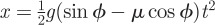 . Frictional anisotropy was measured by placing the snake in one of two orientations on the plane (head up or head down).
2.3. Smart-channel construction
We constructed a rectangular smart-channel (90 cm length and 4 cm height) capable of measuring forces applied by the snake. The channel bottom consisted of styrofoam to enable gripping by the snake. Polished wood was used as sidewalls for the channel, as shown in figure 1. The channel top was left open to facilitate filming. Snakes entering the channel from one end readily pressed the sidewalls of the channel in order to climb. Inclination of the channel was adjusted by supporting one end of the channel at variable heights. Width of the channel was adjusted by moving the sidewalls and bracing them with an additional wood block held in place by self-weight.
Figure 1.

Schematic of the apparatus used to study concertina locomotion. Here, θ is the inclination angle with respect to the horizontal and W is the channel width. The front wall is composed of plexiglass. All of the experiments are conducted on styrofoam. (Online version in colour.)
An electronic ‘measuring wall’ was used to measure the transverse forces applied by the snake to one of the two channel walls. The measuring wall consisted of a linear series of 14 force sensors with a precision of 0.1 g and a size of 3 × 4 cm (Matchbox digital mini-scales from American Weigh). During force measurements, the opposite wall of the channel was replaced with transparent plastic to facilitate reading of the force sensors. Thus, during locomotion in the channel, the snake's flanks pressed against three types of materials: the force sensors, wooden sidewalls and transparent plastic. To ensure that the variation in materials did not affect the friction force generated, we measured the static and dynamic friction coefficients on all materials. We observed that flank friction coefficients (both static and dynamic coefficients) on these materials are direction-independent. We also found that dynamic friction coefficients on all three materials were comparable (0.19–0.31).
2.4. Filming
Plan and side views of the channel were filmed using two high-definition digital video cameras (Sony HDRXR200). The position and speed of the snake's centre of mass were found using image-processing software Matlab. Reported body speeds are averages from films of three periods of motion.
2.5. Statistical analyses
A two-way ANOVA was used to determine the significance of changing channel width and inclination on the kinematics and performance of corn snakes (N = 3) [15]. p < 0.05 was used as the criterion for significance. All statistics were performed using the Statistics Toolbox in Matlab, and the results are summarized in table 1.
Table 1.
Effects of width and slope on kinematics and performance. Tabulated values are given in the form of F (p), where F is the F-statistic and p is the p-value. Bold type indicates statistically significant values.
| effect |
||||
|---|---|---|---|---|
| variable | definition | width (d.f. = 2,6) | slope (d.f. = 2,6) | width × slope (d.f. = 4,18) |
| τ | period | 1.65 (0.2204) | 6.41 (0.0079) | 0.29 (0.8779) |
| ΔL | body extension | 1.04 (0.3743) | 12.96 (0.0003) | 3.15 (0.0398) |
| Lmin | contracted length | 20.48 (0.0000) | 0.56 (0.5806) | 0.52 (0.7229) |
| Lmax | extended length | 13.09 (0.0003) | 6.31 (0.0084) | 0.90 (0.4852) |
| Cmin | min. no. of contacts | 5.36 (0.0149) | 3.03 (0.0735) | 0.78 (0.5540) |
| Cmax | max. no. of contacts | 94.11 (0.0000) | 2.19 (0.1403) | 2.44 (0.0840) |
| Cmin/Cmax | ratio of min. to max. no. of contacts | 12.29 (0.0004) | 8.99 (0.0020) | 2.52 (0.0775) |
 |
velocity of the centre of mass | 1.04 (0.3743) | 12.96 (0.0003) | 3.15 (0.0398) |
| Tmin | min. transverse force | 3.15 (0.0919) | 20.01 (0.0005) | 0.56 (0.6992) |
| Tmax | max. transverse force | 0.94 (0.4247) | 18.54 (0.0006) | 1.04 (0.4381) |
3. One-dimensional concertina model
We modelled a snake as a one-dimensional n-linked crawler by discretizing snakes of mass m into n nodes of equal mass m/n. The repercussions of this simplification will be discussed in §4. Nodes are connected in series by n − 1 inter-nodal lengths li(t), whose kinematics will be recorded from our experiments. A schematic is shown in top and side views in figure 2.
Figure 2.

(a) Plan view and (b) side view of the three-mass model.
The inputs to our model are the observed extensional kinematics li(t), and our output will be the snake's centre of mass position  , defined by
| 3.1 |
and
 |
3.2 |
where xi is the position of the ith node. The kinematics of a node xi may be written using the relations
 |
3.3 |
which arise from definitions in equation (3.2). To move forward, the snake adjusts the distance between its nodes by applying internal extensile or contractile forces, causing the body to fold or unfold between nodes, which in turn slides the belly along the axis of the channel. We will focus on propulsion based on a single travelling wave of extension, starting from the head and moving towards the tail.
A node's body inertia is balanced by gravitational forces mg/n, frictional forces Fi and internal forces fi as well as fi−1 generated by the snake's muscles on either side of node i. Newton's Second Law applied along the axis of the channel yields
| 3.4 |
where  is the acceleration of a node along the snake's body and θ is the inclination of the channel.
3.1. Friction force
In general, the friction force, Fi, consists of components associated with the belly and flanks, which are the surfaces in contact with only the open-topped channel. Moreover, this friction force has two regimes: static or sliding, depending on magnitude of the internal force applied.
The static friction force is defined according to Coulomb's Law. This law states that, at zero velocity, the friction force Fi is equal and opposite to fi − fi−1 −(mg/n) sin θ up until the friction is maximized. This yield point is given by the static friction  , where Ti is the force applied to the wall,
  is the normal force against the bottom of the channel and
  and
and  are the static friction coefficients of the belly and flanks, respectively. Static friction between the flanks and the wall,
  , is direction-independent, as we confirm in our experiments. However, the static friction coefficient between the belly and the styrofoam,
  , depends on the direction:
  is the belly static friction in the forward direction and
  is that of backward direction.
Once the snake begins sliding, the friction force decreases, transitioning to sliding friction. For each surface of the snake in contact with the channel, we use a sliding friction law in which the friction force is 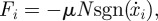 where μ is the sliding friction coefficient corresponding to the two surfaces in contact and N is the normal force applied by the snake to the channel. The sliding friction of the snake's flanks is isotropic and characterized by a single friction coefficient μ = μs. On the belly, sliding friction coefficients in the forward and backward directions are μf and
  , respectively. Each node applies a normal force
  on the sidewalls and
 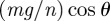 on the bottom of the channel. Together, the friction on the snake may be written as
 |
3.5 |
The friction force on node  for non-zero velocities may be written as
 |
3.6 |
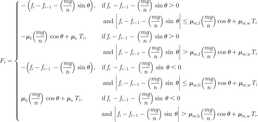
We simplify equation (3.6) by using the Heaviside step function  to distinguish the components in the forward and backward directions. Using this notation, the sliding friction force from equation (3.6) may be written as
| 3.7 |
For the sake of simplicity (as shown by the relative simplicity of equation (3.7) compared with equation (3.5)), we neglect static friction effects. We will instead use only our sliding friction law given in equation (3.7).
3.2. Transverse force
To capture the snake's behaviour of pushing the sidewalls to resist sliding backwards, we make assumptions regarding the magnitude and spatial distribution of the forces applied. First, we assume snakes apply a total transverse force 2Twall sufficient to prevent sliding backwards. Sliding backwards is defined as having an average negative velocity for centre of mass over three periods of motion.
Second, we assume only certain parts of the snake apply force. Namely, parts of the snake apply force only if they are sliding backwards. Consequently, the parts moving forward apply zero transverse force.
Third, among the parts of the snake applying force, we assume the force per unit length is constant. We accomplish this uniform transverse force by discretizing the total transverse force into n − 1 equal portions applied along their points of contact. This assumption is justified because the positions of the force will not affect the speed of the centre of mass. Although they may affect the snake's balancing torques, two-dimensional effects are beyond the scope of our model. We will examine the validity of these assumptions in §4.
All our assumptions together yield the following definition for the net transverse force Ti applied by the ith node:
| 3.8 |
where Twall is the sum of the transverse force applied to a single wall, and  is the velocity of the ith mass.
3.3. Governing equation
Using our definitions of kinematics, friction and transverse force, we may proceed with determining the governing equations for our system, specifically, for the position of the snake's centre of mass. Substituting equation (3.7) into (3.4) yields
 |
3.9 |
Elimination of the internal forces fi is accomplished using the definition of centre of mass in equation (3.2). Applying the definition of transverse force Ti in equation (3.8) yields
 |
3.10 |
Non-dimensionalization of equation (3.10) using the snake's length L and period τ yields
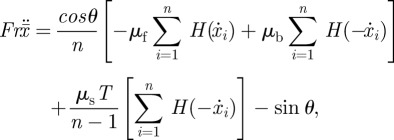 |
3.11 |
where Fr and T are the dimensionless groups
 |
3.12 |
whose values will be determined in our experiments. The combination of equations (3.11) and (3.3), along with the prescribed kinematics li(t), provides a closed system that can be iterated to determine the snake steady-state speed.
3.4. Numerical simulation
Using the state-space form of equation (3.11), the acceleration, velocity and position of the centre of mass are calculated in Matlab. We apply the Dormand–Prince pair method, a member of the Runge–Kutta family of ordinary differential equation solvers, to find the solution of equation (3.11) numerically. The Dormand–Prince pair method uses six function evaluations to calculate fourth- and fifth-order accurate solutions [16]. Using a time step Δt = 10−4, we solve equation (3.11) iteratively to determine the position of the snake's centre of mass  . We assume the snake applies a constant transverse force during its period, and use our numerical solution to calculate the magnitude of the force Twall. This magnitude is the minimum value of Twall for which snake velocity is positive, and is found by starting with a guess of Twall = 0 and increasing Twall in steps of 0.1 snake weights.
3.5. Energetics
Using the energetics of our one-dimensional model, we now examine how channel width and inclination can affect snake kinematics. During a period τ, the average power P of a snake performing concertina motion is given by the time rate of change of its kinetic energy Pkinetic, gravitational potential energy Pgravity and frictional dissipation Dfric. This summation may be written as
| 3.13 |
We estimate these rates of working in equation (3.13) by first estimating the corresponding instantaneous energy states. The kinetic energy of the ith segment of the snake is  , where mi and Vi are its mass and velocity. The gravitational energy of a segment is migzi, where zi is the vertical displacement. The frictional energy dissipation of a segment is
  where μt and μf are friction coefficients in the transverse and forward directions and st and sf are the corresponding displacements in these directions. Backwards friction is not used to dissipate energy because we assume the snake is moving forward.
All together, the rate of change of these energies for n segments over period τ is given by
 |
3.14 |
The power associated with kinetic energy Pkinetic will vanish because each point on the body is periodically at rest. Because  , where
  is the vertical displacement of centre of mass, the rate of change of gravitational energy may be simplified to
  . To provide an upper bound for power, we note that the maximum axial displacement during a period is ΔL and the maximum transverse displacement is equal to the channel width w. Equation (3.14) may be approximated as
| 3.15 |
At high inclinations, the most significant term in equation (3.15) is the one involving gravity. The friction dissipation is of secondary importance because its multiplication by friction coefficients of order 0.2–0.4. Moreover, as illustrated in the electronic supplementary material, video S4, snakes regularly lift parts of their body during concertina locomotion, presumably to reduce the friction dissipation and the associated skin wear. As a result, even less power will be expended on friction. According to equation (3.15), in order to maintain constant power during climbing of steeper slopes (larger θ), the snake should increase its period τ and decrease its body extension ΔL, a prediction we will test in §5.2.
4. Justification of assumptions in our model
We use our experimental observations to justify the assumptions in our model. Specifically, we provide evidence that (i) an adequate number of nodes n is three and (ii) the motion of the centre of mass can be approximated as one-dimensional.
4.1. Node number depends on incline angle
Figure 3a shows a series of body shapes of a corn snake moving through a channel of 2 cm width. Segments of the snake's body have two possible configurations, extended, where the body is mostly straight, or contracted, where the body folds into a series of bends whose apices contact the channel walls. These contact points are the source of anchorage forces for the snake and so are dynamically important in our model. The number of contacts with the walls (figure 4b) varies from a minimum value, Cmin = 5–7 when the snake is in a contracted configuration, to a maximum value, Cmax = 7–15 when the snake is extended.
Figure 3.

(a–c) Video sequences of corn snakes performing concertina locomotion in channels of 2, 3 and 4 cm width. Three phases of concertina locomotion are highlighted in each video sequence. (Online version in colour.)
Figure 4.

Total number of contact points of the snake with the channel walls. (a) Minimum and maximum number of contacts for a corn snake performing concertina locomotion in a horizontal channel of width 4 cm. (b,c) Minimum and maximum number of contact points and (d) their ratio, as a function of channel width and inclination. As shown in (a), a corn snake moving in a horizontal channel of 4 cm width makes minimum of four and maximum of six contacts with the sidewalls. (Online version in colour.)
Figure 4d shows the ratio of the minimum to the maximum number of contact points with the sidewalls, Cmin/Cmax. This ratio may also be approximated by (n–1)/n, where n is the number of nodes in our model. Notably, on horizontal surfaces for all three channel spacings, this ratio is constant ((n−1)/n = 0.62 ± 0.16). Consequently, a good approximation for n is 3 and we model the snake as a three-link crawler.
We note that the number of nodes is strongly affected by inclination. For higher inclinations, Cmin/Cmax varies between 0.4 and 0.9, suggesting that a four- or eight-mass model may be a better model for higher inclinations. Physically, this behaviour makes sense as the snake is using more transverse force on steeper slopes to avoid slipping. By increasing the number of contacts during locomotion, the snake can have more points of support and so less transverse force per contact. Nevertheless, for simplicity, we fix the number of masses as n = 3 throughout this discussion.
4.2. Centre of mass moves one-dimensionally
Figure 5a,b indicates the axial ( ) and transverse (
 ) position of the snake's centre of mass in a channel of 2 cm over 10 periods. The snake moves at constant velocity in the x-direction. Notably, displacement of the centre of mass in the y-direction is less than 10 per cent of the width of the channel. These features are consistent with extension and contraction of the body in one dimension.
Figure 5.

Dynamics of centre of mass motion in a horizontal channel of width 2 cm. (a) Axial and (b) lateral positions of the snake centre of mass. (c) Axial and (d) lateral positions of three points on the snake (1 denotes posterior section, 2 denotes mid section and 3 denotes anterior section of the snake body) as a function of time in dimensionless units. The channel sides are shown in (b,d) using dashed lines. The curves y1 and y3 in (d) are offset vertically by −0.05 and 0.05, respectively. (Online version in colour.)
Although the motion of the centre of mass is one-dimensional, this is not the case for the individual parts of the snake. Figure 3a shows the centre of mass of each third of a snake in a 2 cm channel. Transverse motion is clearly necessary in order for the snake to make contact with the channel sidewalls, as shown by the transverse undulations of each third of the snake. Further observation indicates that concertina, similar to other snake gaits, is strongly three-dimensional, a feature of the locomotion which has received little attention in the literature. Electronic supplementary material, video S4 shows side and top views of a corn snake performing concertina in which it lifts portions of its body while extending them forward. This behaviour is favourable if the energy required for lifting, migzi, is less than the energy dissipated owing to sliding forward, 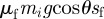 . Nevertheless, for simplicity, we neglect two- or three-dimensional motions in our model.
5. Results
We present the experimental and computational results of our study in §§5.1–5.5. We first discuss our measurements of corn snake frictional properties, body kinematics, force applied to channel sidewalls and snake speed. In the data reported in figures 7–12, we non-dimensionalize length according to the snake length L, time by the snake period τ and transverse force by the snake weight mg. The dimensionless position and time are defined as x = x*/L and t = t*/τ, respectively, where x* is dimensional position and t* is dimensional time.
Figure 7.
Inter-nodal distances l1 and l2 given in terms of the kinematic parameters. Circles and diamonds are the experimental data for l1 and l2, respectively. Solid and dashed lines are the corresponding approximate waveforms used in the model. (Online version in colour.)
Figure 12.

Time course of the transverse force applied by a corn snake (solid lines). Dashed lines show the model predictions for the minimum required transverse force to prevent sliding. The channel has a width of 3 cm and inclination of 30°. (Online version in colour.)
5.1. Snakes double their friction coefficients
We observed that snakes can actively orient their scales to prevent sliding down an incline. Figure 6a–c shows a corn snake digging its scales into the bark of a tree, enabling it to remain vertically perched for long periods of time. Figure 6d,e shows a conscious snake atop styrofoam angling its scales to resist being pulled by its tail. Electronic supplementary material, video S1 and video frames given in figure 6f,g show a snake performing concertina locomotion up a styrofoam plane inclined at 35°. On slopes of this inclination, uphill locomotion is precarious, and the snake often loses its grip and begins to slide. To resist sliding, the snake freezes its body in an S-shaped ‘emergency braking’ configuration causing the snake's ventral contact with the ground to be limited to a few discrete points. It is noteworthy that none of the mechanisms in figure 6a–g are observable on unconscious snakes, suggesting that these responses are consciously rather than passively activated.
Figure 6.

(a) A corn snake ascending a tree. (b,c) Scales are used to grip tree bark asperities. Snake scales at their (d) minimum and (e) maximum angles of attack (flat). (f,g) A snake climbing an inclined surface. Sliding is prevented by emergency braking associated with lifting of the body. (Online version in colour.)
Previous methods to measure friction have relied upon unconscious snakes [6,13] that cannot capture the control of scales we have observed. Consequently, we measured the dynamic friction coefficients of both unconscious and conscious snakes. Table 2 lists the dynamic and static friction coefficients for both conscious and unconscious snakes. The coefficients for unconscious snakes depict a snake's resistance to sliding if it were unable to activate its scales. We calculated the p-value for friction coefficients of conscious and unconscious snakes in forward (p = 0.02) and backward directions (p = 0.0004). The p-value indicates that it is with over 98 percent probability that the friction coefficients of unconscious snakes are greater than or equal to those of conscious snakes [15].
Table 2.
Static and dynamic friction coefficients of (a) conscious and (b) unconscious corn snakes on a styrofoam substrate.
| friction type |
||
|---|---|---|
| direction | static | dynamic |
| (a) | ||
| forward | 0.51 ±0.08 | 0.49 ± 0.09 |
| backward | 0.88 ± 0.04 | 0.79 ± 0.04 |
| (b) | ||
| forward | 0.3 ±0.08 | 0.21 ±0.03 |
| backward | 0.35 ±0.03 | 0.35 ±0.06 |
We found static friction coefficients for conscious snakes were double the corresponding coefficients of unconscious snakes (table 2). Physically, this meant that conscious snakes could maintain their positions on 41° inclines, compared with 19° for their unconscious counterparts. Differences in sliding friction coefficients were not as high: conscious snakes had coefficients nearly 30 per cent higher than their unconscious counterparts. On rougher surfaces, it may be possible for snakes to further increase their friction coefficients.
5.2. Kinematics of concertina motion
Image processing was used to partition the snake into equal thirds, which we refer to as the head, middle and tail. As an example, we use the motion of a snake moving through a 2 cm channel in figure 3a. The centre of mass position of each third is shown by the grey blocks. The kinematics of the snake is given by the inter-nodal distances, l1 and l2, which the snake adjusts by folding and unfolding. We divide the snake's period into three phases (A, B and C), as shown in figure 7. The cycle begins with the snake extending its head in phase A, which is accomplished by bracing the middle and rear parts of its body firmly against channel walls. In phases B and C, the snake's middle and rear, respectively, are drawn forward to meet its head.
The time course of l1 and l2 is indicated by circles and diamonds in figure 7. We roughly approximate (R2 = 0.45) the waveforms using two triangle waves of period τ, and a phase difference τ/2. These waves have amplitudes bounded between Lmin/n and Lmin/n+ΔL, corresponding to the snake's contracted and extended body configurations. Using image analysis, we measured the periods and amplitudes of the corresponding triangle waves for all snakes filmed for snakes over a range of inclines (0°, 30° and 60°) and channel widths (2, 3 and 4 cm).
Figure 8a shows the changes in period τ over a range of inclinations and channel widths. We observed τ increases significantly with increasing inclination. Specifically, snakes moved slower on increasing inclinations: periods increased from 3 to 6 s as inclination increased from 0° to 60° at a channel of width 4 cm. This slower climbing is qualitatively consistent with the greater energy needed to climb higher inclinations. By climbing more slowly at higher inclines, snakes can keep their power use constant, as previously predicted in §3.5.
Figure 8.

(a) Period, (b) normalized ΔL, (c) normalized minimum length and (d) normalized maximum length of corn snakes as a function of slope and non-dimensionalized channel width. (Online version in colour.)
Figure 8c shows that extensional length ΔL is significantly reduced by increasing channel inclination (p = 0.0003). Figure 8c,d shows that contracted lengths Lmin and extended lengths Lmax are highly dependent on channel width. For the thinnest channels, snakes exhibited Lmin values of 0.8 snake lengths, which decreased to 0.68 for the widest channels. This decrease in contracted length with wide channels is due to a snake's finite length: as channels widen, a snake cannot reach as far along the channel while simultaneously maintaining its contact points with the sidewalls. For instance, in horizontal channels of 5 cm width, snakes make fewer than seven contact points with the walls, which is fewer than the observed maximum of 15 contacts in 2-cm-wide channels. Snakes in 5 mm or wider channels often abandon concertina motion and resort to slithering motion as shown in the electronic supplementary material, video S3.
5.3. Body speed
Figure 9a shows measurements of body speed  . Clearly, snake speed is significantly affected by channel slope (p = 0.0003). Speed
  decreases from 0.17 to 0.05 as channel inclination increases from horizontal to 60°. For comparison, we also include snake speeds measured by Jayne [8] on horizontal surfaces of various channel widths, as shown by the circles. The correspondence between our experimental results and others is good, despite the different snake sizes and species used by Jayne (Nerodia fasciata and Elaphe obsoleta of lengths 100 and 159 cm, respectively). This correspondence suggests that snakes of a variety of sizes and species may use similar kinematics to move through channels.
Figure 9.

(a) Speed and (b) applied transverse force as a function of slope and channel width. Model predictions are given by black squares; velocities measured by Jayne [8] are given by black circles for comparisons. (Online version in colour.)
To check the consistency of our model, we also plot in figure 9a speed predictions from our theoretical model. Speed is calculated using equation (3.11) using the methods described in §3.4. The speed predicted is based on the assumption the snake applies sufficient transverse force to prevent backwards sliding. As a result, the predicted speed corresponds roughly to the ratio of the extension ΔL to the period τ:
| 5.1 |
Differences between the predicted speed and equation (5.1) result from the snake sliding backwards owing to our modelling of sliding rather than static friction. Comparisons between our model and experiments are favourable suggesting that our model is consistent with the locomotion observed.
Our model can also predict the variation of snake speed with frictional anisotropy. This trend would be more difficult to study experimentally as it would require experiments with new substrates such as styrofoam of varying roughness. We examine in figure 10a the predicted speed of a three-mass snake model in a horizontal 3 cm channel. In our experimental data on styrofoam, the backward-sliding friction is 1.6 times greater than forward friction. In fact, this is the optimum anisotropy for a snake. Below this anisotropy, the snake slides backwards and must modulate body kinematics to maintain its position. Above this anisotropy, there is a negligible 3 per cent gain in speed.
Figure 10.

(a) The velocity of centre of mass as a function of dynamic friction anisotropy μb/μf in a horizontal channel of 3 cm width. (b) The velocity of centre of mass as a function of transverse force T for a channel of width 3 cm and inclination of 30°. Note that the negative velocities are not steady-state velocities, but represent average values over three periods of motion. (Online version in colour.)
5.4. Measured transverse force
We measured the transverse force applied by the snake over a range of channel widths and inclinations. Figure 11 shows the forces applied to one wall of a channel (width: 3 cm; inclination: 30°). The snake's instantaneous body configurations are shown in the insets of figure 11, and show clearly that peaks in force are associated with kinks in the snake. Individual wall contacts have an associated force magnitude ranging from 0.5 to 1.5 snake weights. The tips of the snake's head and tail applied a transverse force less than the resolution of our sensors (1 mN).
Figure 11.

The transverse force applied by a corn snake, as a function of time and position along the body. The channel has a width of 3 cm and inclination of 30°. (a–d) Instantaneous force profiles during one period of motion. Insets show the corresponding body shape of the corn snake. (Online version in colour.)
We observed the segments of the snake remained stationary when applying force to the sidewall. We can thus apply Newton's Third Law to infer that the force applied to the opposite wall was equal in magnitude to that measured. This observation justifies the use of equation (3.8) in our modelling section.
The solid line in figure 12 shows the time course of the total applied force T associated with the snake in figure 11. The applied force T is double that measured on one wall of the channel and is non-dimensionalized by the snake weight. The dotted line shows the minimum applied force (two times body weight) required to prevent sliding. Clearly, the snake is pushing with greatest force (eight times body weight) in phases A and C, when moving either its head or tail. It pushes with least force (two times body weight) in phase B, when moving its middle.
We measured the minimum and maximum force applied by the snakes across a range of channel widths and inclines. The box and whiskers plot in figure 9b shows the range of forces measured. Transverse forces increase significantly with increasing inclination angle. At 60° and a channel width of 4 cm, transverse pushing forces increase to 400 per cent of the value measured on a horizontal surface (from T = 0.9 to 3.6).
5.5. Predicted transverse force
The dashed lines in figure 12 show the time course of our predicted transverse force, which is the minimum force to prevent sliding backwards. The force is calculated by integrating equation (3.11) using the snake's measured kinematics and friction coefficients for a channel of 3 cm width and 30° inclination. The minimum required force averaged over the period is T = 2.1 snake weights. This magnitude is constant within each phase (A–C) of locomotion, as the snake is moving at a steady-state speed. However, additional force must be applied at the transition between phases, when the snake accelerates one part of its body and decelerates another. This additional force is manifested as delta functions, because our kinematic input is characterized by triangle waves that contain discontinuities in slope.
Figure 10b shows the sensitivity of steady-state velocity to the magnitude of the normal force. For applied forces less than 2.1 times snake weight, the snake will slide backwards. Thus, it is of utmost importance that the snake's applied force exceeds this threshold. As we shall see, snakes appear to apply a factor of safety in order to avoid being below this threshold.
Square points in figure 9b represent force predictions from our model for various inclines. Our model performs well in predicting the transverse force at inclinations of 30° and 60°. On horizontal surfaces, snakes appear to be pushing with more force than necessary. We surmise that the additional transverse force applied by the snake acts as a factor of safety.
6. Discussion
6.1. Active control of friction
An important and surprising finding of our study was that snakes can double their friction coefficients on styrofoam by active control of their scales. This ability may extend to materials in the snake's habitat, as shown by our qualitative experiments with tree bark. Future investigators of snake locomotion should choose their test surfaces carefully as snakes have tremendous control of their friction over certain surfaces.
Previous literature on snake locomotion neglects discussion of active control of friction, possibly for several reasons which we speculate on here. Traditionally, measurement of friction coefficient was performed on unconscious snakes. Furthermore, these measurements were carried out using man-made materials such as glass, sandpaper and wood [6]. Such surfaces are not sufficiently rough and compliant as the rough nappy materials found in nature, which in our observations generate high anisotropy. Previous studies in which friction coefficients were measured on smooth surfaces have importance in their own right, as they demonstrate the range of snake adaptability. As we saw in our model, a snake climbing a channel uses both belly friction and flank friction from transverse pushing. If the former is insufficient, then the snake will compensate with increased pushing, and vice versa.
6.2. Safety factors in concertina motion
Over six decade ago, Gray [5] and Jayne & Davis [7] reported that pushing channel sides was a necessary part of concertina motion. A key result of our study is our measurement of the transverse force applied. While force platforms are quite typical in studies of legged locomotion [17], they are quite rare in limbless locomotion, with the exception of the measurement of caterpillar [18] and earthworm forces [19].
We observed that snakes can push the sidewalls with up to nine times their own weight and with a safety factor of 400 per cent relative to the minimum force to prevent sliding. Such a large safety factor has been observed by previous researchers for studies of gripping. Johansson & Westling [20] studied the grip force applied by human hands to rough as well as slippery objects. They found a human hand applies grip force with a safety margin of around 175 per cent (for lifting a suede-covered object weighing 400 g). They emphasize that the lower the friction coefficient of the object, the higher the factor of safety.
What are the limits of concertina locomotion? The steepest incline climbable depends on the limits of the snake's transverse force. In studies of earthworms, Quillin [19] reports a maximum radial force of 10 times body weight for a 6 g earthworm in a horizontal burrow of 0.6 worm diameters. This value is comparable to the snake's pushing ability (nine times body weight), suggesting the possibility of a universal law across scales. In a much narrower burrow of 0.97 worm body diameters, the radial force drops to only 1.5 times the earthworm weight [19]. In comparison, we find snakes are more effective in narrow channels: they have no problem applying forces nine times their weight. The snake's bending of the body into folds thus appears to be a robust method for generating transverse force across channel widths.
During concertina on steep inclines, snakes appear to be approaching their limits of transverse force. We observed a corn snake performing concertina while dragging a load. In a channel of width 3 cm and slope of 30°, a corn snake pushed transversely with 11 times its weight while dragging axial loads of 2.5 times its weight. This transverse force is only 30 per cent more than the corresponding maximum of transverse force (two to eight times its weight) without a load.
6.3. The need for higher dimensional models
The main contribution of our simple model is the ability to compare quantitatively the contributions of ventral friction with transverse pushing. Such comparisons would be more difficult to do experimentally. Because there is no closed-form analytical solution for equation (3.11), we presented numerical integration methods to determine these trends, which may be of use to other investigators studying climbing.
Our model could be improved in several ways to decrease its error and to provide further insights into the mechanisms underlying concertina motion. First, our model does not consider the effect of body lifting and lateral motion, which clearly have an impact on energy consumption, as discussed in §3.5. A three-dimensional model involving friction has not been attempted, although three-dimensional models assuming infinite friction have been developed for sidewinding [21]. Perhaps similar methods may be applied to concertina motion.
Stochasticity or behavioural matters will need to be taken into account if a higher dimensional model is implemented. In our experiments, we observed body segments often move transversely in an irregular manner (figure 5d). The source of this irregularity is unclear. We speculate that small changes in channel width or roughness may cause the snake to choose one side of the channel over another. The head or tail of the snake often clings preferentially to one side of the channel for several periods at a time. For example, the head is slid along the left side of the channel for most of the 10 periods shown in figure 5d. One mechanical advantage of this behaviour is the channel walls provide stability during forward motion. Biologically, the preference for one side of the channel is consistent with the view that snakes have a ‘handedness’ [22,23].
Finally, because our model neglects static friction, it cannot capture the stick–slip phenomena that we observed in our experiments. We have implemented static friction in a model for Scalybot, a two-segment snake robot [14]. We are currently working on a generalized static friction model for nodes of higher order using equation (3.5). We are also currently studying the mechanics of a single scale's stick–slip phenomena.
7. Conclusion
We performed a series of experiments to measure frictional properties of snakes and their kinematics when climbing in a channel. A theoretical model was used to predict the snake's transverse force. Using this prediction, we were able to measure the snake's factor of safety in generating these transverse forces.
In summary, similar to most kinds of snake locomotion, propulsion through channels relies heavily on frictional effects. A snake propels itself in a channel using a series of extensions and contractions, in which a portion of its body extends forward while the remainder anchors. We found anchorage relies on two mechanisms to augment friction: (i) transverse pushing against channel walls and (ii) the control of belly scales to grip the bottom of the channel. The former is an active mechanism requiring energy. The latter is a passive structural means of achieving anchorage, whereby force is mediated by the snake's weight. These dual anchorage methods are necessary to overcome the challenges of climbing uphill. On slopes of increasing inclination, anchorage via belly friction becomes less effective owing to the decreasing normal force between the belly and the channel bottom. Consequently, snakes tend rely upon belly friction when travelling on horizontal surfaces and transverse pushing when on steep slopes.
Acknowledgments
The authors thank M. Shelley for his early contributions, Paul Cook for helping with experiments, Tim Nowak for photography and the NSF (PHY-0848894), Georgia Tech and the Elizabeth Smithgall Watts endowment for support.
References
- 1.Erkmen I., Erkmen A. M., Matsuno F., Chatterjee R., Kamegawa T. 2002. Snake robots to the rescue! Robot. Autom. Mag. IEEE 9, 17–25 10.1109/MRA.2002.1035210 (doi:10.1109/MRA.2002.1035210) [DOI] [Google Scholar]
- 2.Kassim I., Phee L., Ng W. S., Gong F., Dario P., Mosse C. A. 2006. Locomotion techniques for robotic colonoscopy. Eng. Med. Biol. Mag. IEEE 25, 49–56 10.1109/MEMB.2006.1636351 (doi:10.1109/MEMB.2006.1636351) [DOI] [PubMed] [Google Scholar]
- 3.Yim M., Roufas K., Duff D., Zhang Y., Eldershaw C., Homans S. 2003. Modular reconfigurable robots in space applications. Auton. Robots 14, 225–237 10.1023/A:1022287820808 (doi:10.1023/A:1022287820808) [DOI] [Google Scholar]
- 4.Wiedemann E. 1932. On the biology of feeding the adder Vipera berus L. Zool. Anz. 97, 278–286 [Google Scholar]
- 5.Gray J. 1946. The mechanism of locomotion in snakes. J. Exp. Biol. 23, 101–120 [DOI] [PubMed] [Google Scholar]
- 6.Gray J., Lissman H. W. 1950. The kinetics of locomotion of the grass-snake. J. Exp. Biol. 26, 354–367 [Google Scholar]
- 7.Jayne B. C., Davis J. D. 1991. Kinematics and performance capacity for the concertina locomotion of a snake (Coluber constrictor). J. Exp. Biol. 156, 539–556 [Google Scholar]
- 8.Jayne B. C. 1988. Muscular mechanisms of snake locomotion: an electromyographic study of the sidewinding and concertina modes of Crotalus cerastes, Nerodia fasciata and Elaphe obsoleta. J. Exp. Biol. 140, 1–33 [DOI] [PubMed] [Google Scholar]
- 9.Keller J. B., Falkovitz M. S. 1983. Crawling of worms. J. Theor. Biol. 104, 417–442 10.1016/0022-5193(83)90115-7 (doi:10.1016/0022-5193(83)90115-7) [DOI] [Google Scholar]
- 10.Gray S. J. 1968. Animal locomotion. London, UK: Weidenfeld & Nicolson [Google Scholar]
- 11.Zimmermann K., Zeidis I., Behn C. 2009. Mechanics of terrestrial locomotion: with a focus on non-pedal motion systems. Berlin, Germany: Springer [Google Scholar]
- 12.Chernousko F. L. 2005. Modeling of snake-like locomotion. Appl. Math. Comput. 164, 415–434 10.1016/j.amc.2004.06.057 (doi:10.1016/j.amc.2004.06.057) [DOI] [Google Scholar]
- 13.Hu D. L., Nirody J., Scott T., Shelley M. J. 2009. The mechanics of slithering locomotion. Proc. Natl Acad. Sci. USA 106, 10081–10085 10.1073/pnas.0812533106 (doi:10.1073/pnas.0812533106) [DOI] [PMC free article] [PubMed] [Google Scholar]
- 14.Marvi H., Bridges J., Meyers G., Russell G., Hu D. L. 2011. Scalybot: a snake-inspired robot with active control of friction. In Proc. ASME Dynamic Systems and Control Conf., Arlington, VA, 31 October–2 November 2011, pp. 443–450 [Google Scholar]
- 15.McDonald J. H. 2009. Handbook of biological statistics. Baltimore, MD: Sparky House Publishing [Google Scholar]
- 16.Dormand J. R., Prince P. J. 1980. A family of embedded Runge–Kutta formulae. J. Comput. Appl. Math. 6, 19–26 10.1016/0771-050X(80)90013-3 (doi:10.1016/0771-050X(80)90013-3) [DOI] [Google Scholar]
- 17.Alexander R. M. N. 2003. Principles of animal locomotion. Princeton, NJ: Princeton University Press [Google Scholar]
- 18.van Griethuijsen L. I., Trimmer B. A. 2009. Kinematics of horizontal and vertical caterpillar crawling. J. Exp. Biol. 212, 1455–1462 10.1242/jeb.025783 (doi:10.1242/jeb.025783) [DOI] [PubMed] [Google Scholar]
- 19.Quillin K. J. 2000. Ontogenetic scaling of burrowing forces in the earthworm Lumbricus terrestris. J. Exp. Biol. 203, 2757–2770 [DOI] [PubMed] [Google Scholar]
- 20.Johansson R. S., Westling G. 1984. Roles of glabrous skin receptors and sensorimotor memory in automatic control of precision grip when lifting rougher or more slippery objects. Exp. Brain Res. 56, 550–564 10.1007/BF00237997 (doi:10.1007/BF00237997) [DOI] [PubMed] [Google Scholar]
- 21.Burdick J. W., Radford J., Chirikjian G. S. 1993. A sidewinding locomotion gait for hyper-redundant robots. In Proc. IEEE Int. Conf. on Robotics and Automation, 2–6 May 1993, pp. 101–106 [Google Scholar]
- 22.Hoso M., Asami T., Hori M. 2007. Right-handed snakes: convergent evolution of asymmetry for functional specialization. Biol. Lett. 3, 169–173 10.1098/rsbl.2006.0600 (doi:10.1098/rsbl.2006.0600) [DOI] [PMC free article] [PubMed] [Google Scholar]
- 23.Roth E. D. 2003. Handedness in snakes? Lateralization of coiling behaviour in a cottonmouth, Agkistrodon piscivorus leucostoma, population. Anim. Behav. 66, 337–341 10.1006/anbe.2003.2228 (doi:10.1006/anbe.2003.2228) [DOI] [Google Scholar]