

Abstract
Herein long-term delivery of proteins from biodegradable thin film devices is demonstrated, where a nanostructured polymer membrane controls release. Protein was sealed between two poly(caprolactone) films, which generated the thin film devices. Protein release for 210 days was shown in vitro, and stable activity was established through 70 days with a model protein. These thin film devices present a promising delivery platform for biologic therapeutics, particularly for application in constrained spaces.
Keywords: Nanoporous, drug delivery, biodegradable, polycaprolactone, controlled release, zero-order nanostructured
Devices and vehicles for drug delivery have made excellent strides to improve therapeutic outcomes and enhance efficacy of established and emerging drugs.1–4 Among the breadth of approaches, nanomaterials have received considerable attention given the unique properties that emerge at this size scale.5–7 Much of this attention has focused on particle-based technologies, such as liposomes, micelles, and nanoparticles.8–10 These approaches have demonstrated improved bioavailability, localized delivery, extended systemic circulation times, and decreased toxicity for a variety of indications, making them particularly attractive strategies for drug delivery.
While less prominent, nanostructured membranes have also been demonstrated as a promising component in drug delivery devices.11 A simple membrane-based nanostructured device contains a therapeutic loaded directly in membrane pores or in a reservoir, where the membrane is responsible for characteristic release kinetics. When a diffusing molecule is of comparable size to membrane pore size (e.g. as low as sub-nanometer for small molecules to as much as tens of nanometers for macromolecules), controlled release may occur by a process of single file or hindered diffusion.12 Devices satisfying this constraint commonly exhibit zero-order release, providing a means to control release rate and device payload. This approach to controlled release is particularly compelling with the increasing prevalence of biologic drugs, where therapeutic size is on par with a variety of nanostructured materials. To date, such devices have been largely based on inorganic materials, such as silicon, alumina, or titania, given the relative ease of nanostructure fabrication.11–14 While nanostructured inorganic materials can be fabricated with well-ordered and uniform features, these materials are generally rigid and lack tunable degradation behavior. Given the scope and complexity of disease indications, existing inorganic materials insufficiently address the range of therapies where nanostructures membranes may be suitably deployed.
Polymeric nanostructured membranes offer an alternative in materials selection and properties and can be fabricated in a variety of ways.15 Specifically, the design of nanostructured biodegradable polymers is of interest for indications where explantation is undesirable. Utilizing a combination of solvent, temperature, and phase separation techniques, generating nanostructures in any arbitrary polymer is usually possible, albeit largely through trial-and-error.16 Unfortunately, this approach is nontrivial, and optimizing membrane properties according to particular design requirements is challenging. Alternatively, photolithography produces structures explicitly defined by the user,17 yet infrastructure requirements and processing complexity are generally unrealistic for polymeric membrane fabrication. Bombarding polymer films with high energy particles, or track etching, can yield membranes with highly uniform nanoscale pores but necessitates a limited pore density to avoid pore coalescence; furthermore, track etch membrane fabrication requires unique equipment and has rarely been applied to degradable polymers.18 Layer-by-layer self assembly19 or block copolymer self assembly20,21 are very attractive nanoscale approaches, but both have significant material constraints that limit their implementation with an arbitrary polymer or in robust free-standing nanostructured membranes. Lastly, template-based membrane fabrication is a generic route compatible with a wide range of polymers, where nanostructured features are predicated by template structure and the processing associated with template removal;22 the most significant hurdles for template fabricated membranes are template selection and production of membranes that are physically robust.
In order to utilize the controlled release properties of hindered diffusion with a degradable material, it is necessary for the material structure to remain intact throughout the course of delivery. Among biodegradable polymers, poly(caprolactone) (PCL) has emerged as a compelling candidate for this role. As PCL degrades by hydrolytic scission, its hydrophobic backbone prevents significant aqueous solubility for degradation products larger than monomers or dimers.23,24 As a consequence, PCL degradation occurs in two phases: little structural degradation occurs until a critical molecular weight is reached, upon which the probability of producing soluble degradation products increases dramatically. Implemented in a nanostructured device, such a material allows structurally controlled release during the initial phase of degradation, and subsequent physical breakdown and resorption after the therapeutic lifetime of the device is complete.
Many examples of nanostructured PCL have been demonstrated, including nanoparticles, nanofibers, and nanostructured membranes.24 Despite the depth of literature, only a few approaches to fabricate nanostructured PCL membranes have been presented. Inducing phase separation in drop-cast films has been used to generate films (~50 μm) of PCL that consisted of a nanoporous surface layer and a microporous backing membrane.25–27 Control over process conditions such as casting surface, solvent selection, coagulation bath conditions, and processing temperature were shown to affect membrane morphology. This approach achieved sub-100 nm pore diameter,26,27 yet the lower limit of pore size, dispersion of pore diameters, and ultimate pore density remains unclear. While these membranes can be simply fabricated and are suited for certain applications, the capacity to control membrane structure more precisely is valuable for long-term controlled release devices. Template-based fabrication was shown to achieve smaller and denser nanostructures through inversion of a nanorod template; however, thickness of these membranes was limited by the thickness of the template material (< 1 μm) and were markedly fragile as a result.28
In this report, we describe the use of biodegradable nanostructured membranes as the active element in drug delivery device capable of controlled release. Through incorporation of a porous support, template fabricated nanostructured membranes were generated with substantially improved durability. Placing pelleted protein between polymer thin films and heat sealing around the protein produced devices capable of zero-order release with durations in excess of 6 months. When using IgG as a model therapeutic, stable affinity was demonstrated over the course of months, indicating protein stability can be maintained in this device configuration. Stability of nanostructured features in vitro was demonstrated over the course of protein release and accounts for the capacity for zero-order kinetics over this duration.
Fabrication of submicron-thick nanostructured PCL membranes was previously demonstrated utilizing a template-based approach.28 While zero-order diffusion was shown with a model protein over a relatively short time scale, these films lacked the robustness required for feasible device fabrication and deployment. To alleviate this limitation, an additional layer was augmented onto the template fabricated membrane that added structural support and improved ease of handling. Figure 1 shows the template-based fabrication scheme for a supported nanostructured membrane and a prototypical membrane generated by this approach.
Figure 1.

Fabrication of nanostructured membranes. (A) Onto a clean silicon substrate (B) a zinc oxide seed layer is spin cast and nanorods are grown hydrothermally. (C) A thin PCL layer is spin cast onto the ZnO template followed by (D) a PCL and PEG mixture. (E) Deionized water dissolves the PEG-phase from the supporting layer and sulfuric acid etches the ZnO template to generate a supported nanostructured PCL thin film. (F) SEM image of a typical nanostructured PCL film, (G) with a thin layer of nanostructured PCL on supporting membrane.
In this implementation, zinc oxide was chosen as the template material for the nanostructured membrane using techniques detailed and characterized previously (complete experimental procedures detailed in the Supplementary Information).28 Briefly, 0.75 M solution of zinc acetate (ZnAc2) and ethanolamine in 2-methoxyethanol was cast onto silicon wafers and annealed at 400°C to generate a ZnO seed layer. From this seed layer, ZnO nanorods were grown in 5 mM ZnAc2 solution in deionized water at 85–90°C. Typical ZnO rods produced with this process exhibited diameters of 20–30 nm and lengths of approximately 0.75–1 μm, equivalent to those in our previous report.28 Many nanostructured materials may satisfy the requirements for a template material: zinc oxide was selected for these membranes given its minimal infrastructure requirements, appropriate feature size, relative ease of template removal, and scalable processes. While a considerable range of ZnO nanorod variants exist in the literature,29–32 the focus of this work was pairing nanoscale membrane features with a model protein, so many zinc oxide growth variations were left unexplored. Examples of larger well-oriented ZnO rods have been synthesized up through the micron scale;32 however, an alternate to hydrothermal growth may be required for sub-20 nm ZnO rods. Depending on future needs, an alternative template may be used, wherein a suitable material should be considered on merits of processing ease, cost, throughput, and scalability, as well as physical size requirements and compatibility with the polymer(s) of interest.
To generate the nanostructured features of our membranes, a thin film of PCL was spin cast onto the ZnO template. As in the previous report,28 this was done such that the template penetrates the thickness of the polymer film, which was achieved through control of polymer solution concentration and spin speed. The supporting polymer structure was generated by spin casting a solution of PCL and poly(ethylene glycol) (PEG) in 2,2,2-trifluoroethanol (TFE) that phase separates as the solvent dries during the casting process.33 At appropriate concentrations, PEG forms an interconnected network spanning the supporting film layer. Finally, the PEG can be removed with deionized water to generate a porous supporting PCL film and the ZnO template can be etched with sulfuric acid to generate nanostructured PCL pores. The nanostructures generated with these techniques are predicated by template structure, and consequently there is versatility in polymer selection: spin-castable polymers compatible with acidic etching can be used with this template and process.
In contrast to template-based nanostructure fabrication, phase separation is a process requiring optimization based on the particular polymers selected. The pore structure and film thickness of the resulting membrane are dependent on overall polymer concentration, PCL:PEG ratio, polymer molecular weight, and spin casting conditions. Utilizing commercially available PCL and PEG, a range of PCL:PEG ratios and PEG molecular weights were considered for ultimate solution composition (candidates listed in Table S1 and summarized in Table 1). On one extreme, casting from solutions with low molecular weight PEG (<2 kDa) resulted in continuous, uniform, and durable thin films that unfortunately lacked necessary porosity. On the other hand, casting from solutions with high molecular weight PEG (>3.4 kDa) resulted in thin films with irregular porosity that lacked the durability necessary to be a supporting film layer. For an intermediate range of PEG molecular weight (2–3.4 kDa), it was possible to cast suitable thin films that were both continuous and uniform while maintaining porosity spanning the full film thickness. Within this range, thin films were increasingly compliant as molecular weight was increased, and further study focused on the lower end of this molecular weight range given its superior durability. Focusing on 2 kDa PEG, variation of PEG concentration was examined. At low PEG concentrations, high quality thin films were generated, but a continuous porous structure was absent. While at high PEG concentrations, the films lost durability, became difficult to handle, and were deemed unusable. Cross-sectional scanning electron microscopy of these films cross sections revealed top-to-bottom continuous porous network only for films cast from relatively high PEG concentration (Figure 2), indicating a minimum PEG concentration to produce porosity spanning the thin film. For combinations that generated continuous films, there was a consistent tradeoff between thin film robustness and porosity. Because protective reinforcement was the prime function of these supporting membranes, superior film forming capacity took priority over porosity. Consequently, the combination utilizing 150 mg/ml of PCL (MW~80 kDa) and PEG (MW~2 kDa) was selected in our device design. While this approach is empirical in its development, it is simple and only requires one additional material – PEG – a well-established biopolymer. If alternate polymers or thin film properties are required for a supporting polymer, a variety of additional fabrication techniques exist.15
Table 1.
Porosity of PCL thin films cast from PCL-PEG mixtures.
| PEG Composition | Average Diameter (μm) | Pore Density (cm−2) | Film Quality | |
|---|---|---|---|---|
| Conc. (mg/mL) | MW (kDa) | |||
| 100 | 2 | – | – | ++ |
| 150 | 1 | – | – | ++ |
| 150 | 2 | 0.54 ± 0.32 | 4.2 × 10⁵ | ++ |
| 150 | 3.4 | 0.84 ± 0.95 | 3.5 × 10⁶ | + |
| 200 | 2 | 0.97 ± 0.77 | 2.2 × 10⁶ | − |
Molecular weights reported are based on number average. Film quality indicated with (−) substandard, (+) good, and (++) excellent film formation. The details of the PEG composition used for device fabrication is indicated in bold.
Figure 2.

Morphology of porous PCL thin films. Cross-sectional SEM images of porous PCL thin films generated from PCL and PEG solutions with compositions of 150 mg/mL PCL (80 kDa) and (A) 100 mg/mL PEG (2 kDa), (B) 150 mg/mL PEG (2 kDa), and (C) 200 mg/mL PEG (2 kDa), and (D) 150 mg/mL PEG (3.4 kDa).
All nanoporous devices herein were fabricated from three elements: a nanoporous film with a microporous supporting layer, a pellet of protein, and a non-porous PCL film that encases the pellet. Devices were sealed utilizing a hot plate as a uniform heat source, and a stacked apparatus was used to assemble the device layers for heat sealing (Figure 3). An annulus and upper support were fabricated from poly(dimethylsiloxane) (PDMS) to provide structural support and allow conformal contact between the layers of the device, where the lower annulus minimizes heating to the protein and membrane. A weight was applied (~800 g) that was sufficient to maintain uniform film contact and sealing around the protein. At the lab scale, this approach is simple and adequate for device sealing; alternative methods such as resistive heating, optical welding, ultrasonic welding, or covalent chemical bonding may prove superior depending on fabrication needs. For this work, all devices were assembled around a 3 mm diameter pellet of protein (typically 0.5–2 mg). A 4 mm PDMS annulus was used to allow for registration of the pellet relative to the annulus and allowed the polymer to conform to the pellet. This allowed for an ultimate device geometry of 5 mm once cut to size. For several experiments presented here, devices were left uncut to facilitate handling and sampling; it is not expected that this will impact device behavior in vitro and will be unnecessary for future deployment in vivo. Stereoscopic inspection of devices ensured the absence of any gross defects present in the starting materials or generated during the sealing process.
Figure 3.
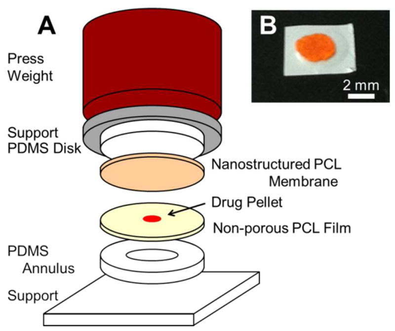
Assembly of nanoporous thin film devices. (A) From the bottom up, devices consist of a flat PCL film, a drug pellet, and a nanostructured PCL film sandwiched between supporting structures using a press weight. The apparatus containing the constituent device layers is placed on a hot plate to fuse the PCL films. The annulus base support causes the device center to experience considerably less heating. (B) Example of a prototypical device loaded with FITC-BSA.
Prior to testing long-term release, devices were aggressively vortexed for 15 seconds in phosphate-buffered saline (PBS) to pre-stress devices and accelerate any susceptible failure modes present in the seal or films. To assess protein release, devices were placed in PBS at 37°C to simulate physiological conditions and the contents of this reservoir were periodically exchanged to measure protein release. Figure 4 shows the release behavior of fluorescein isothiocyanate-labeled bovine serum albumin (FITC-BSA), a model protein. Over the course of 210 days, the release was zero-order in nature, even after releasing over half the device payload. Because release rates are relatively slow, it is possible to approach the limit of a perfect sink (i.e. [BSA]device ≫ [BSA]reservoir) by exchanging the entire contents of the elution reservoir. These conditions ensure the release of protein was representative of the molecule-device characteristics rather than an artifact of the testing approach. Heat sealed devices were capable of minimal leakage over extended periods: for instance, immunoglobulin G (IgG) loaded PCL devices fabricated from two non-porous PCL films exhibited a leakage of <100 ng/day over the course of several months. While the release rates presented here are informative, it is likely necessary to optimize device parameters for any particular therapeutic. For instance, in the case of BSA, estimates of absorption on hydrophobic surfaces can be several nanometers in thickness,34,35 constricting the effective pore diameter and influencing maximal release rates. Using silicon slit-pore membranes as a guide, one expects zero-order release for effective pore size less than 3–5 times the therapeutic size.12,36,37 This number may be higher yet for our PCL membranes since they are nanoscale in two dimensions, whereas slit-pores are only nanoscale in one-dimension. Depending on the therapeutic of interest, the impact of physiosorption or other effects on effective pore size may vary significantly. This emphasizes the need to reevaluate molecule-device interactions and dosing requirements for any particular drug and disease indication. Regardless, device design will require coordination of release rates and drug clearance to maintain effective therapeutic concentrations.
Figure 4.

Nanostructured PCL device release. Release rate and cumulative release of FITC-BSA from nanoporous devices over time for a membrane area of 7 mm2 and initial payload of 670 ± 120 μg (n=3). Average release rate was 1.6 μg/day. Error bars indicate deviation in measured rates of release and account for error propagation associated with cumulative mass released.
For these devices, it is possible to increase or decrease device release rate by modulating membrane area. Either patterning the template layer (accomplished with photolithography or soft contact printing38) or intentionally melting a fraction of the membrane area are straightforward ways to reduce the membrane area and proportionally decrease drug release. The devices presented here are monodirectional in nature – utilizing one nanoporous and one non-porous PCL film; an implementation with two nanoporous films is a clear route to double release rate. Due to the added complexity of such a device, it is likely that additional care will be necessary during the sealing process. Alternatively, spatially larger devices may be fabricated to increase release rates if design requirements allow. To date, these efforts have focused on the delivery of biologics and macromolecular therapeutics, so implementation of this particular phenomenon for controlled small molecule delivery is expected to require modification to film nanostructure dimensions. If an alternate template was necessary, polymer compatibility with the new template and its removal process would need to be reevaluated. Otherwise a phenomenologically distinct approach, like the use of nanoparticles, may be more practical in this case.8,10
Our thin film devices were designed such that payload scales independently of membrane thickness or area – separating overall payload from daily release rate. While certain limitations associated with overall device thickness and available payload remain, a centralized reservoir offers design advantages. Because the payload is not loaded within the pores of the device, payload formulation and preparation can be completed in parallel to membrane fabrication. In addition, because the reservoir and membrane properties are independent, pore diameter or membrane area can be used to optimize release rate without affecting device payload. In contrast, a device with drug loaded into nanostructured pores may need to be very thick for release over extended periods.
One challenge present in these layered devices is sealing the polymer films, which will require procedures to minimize heating of biologic payloads. However, given that PCL melts at ~60°C, implementing methods for localized heating should be sufficient to minimize thermal load on the therapeutic. In an effort to assess the functional integrity of biologics release from these devices, IgG was used as a model protein for binding affinity. IgG released from thin film devices was analyzed with a micro-bicinchoninic acid (μBCA) assay and a bovine-IgG enzyme-linked immunosorbent assay (ELISA) in order to determine both the total mass of IgG released from devices and the fraction that was active. Through comparison of the ELISA and μBCA results, it was possible to extract the activity of the IgG released over time (Figure 5), which was shown to be stable through 70 days. Because the activity of as-received lyophilized IgG powder was lower than the stabilized ELISA standards, relative activity was calculated by referencing the results to lyophilized IgG powder prior to incorporation into a device. While not applicable to an arbitrary therapeutic, these results are a positive indicator that protein may be stably maintained within such devices. Furthermore, because our device fabrication does not constrain protein preparation, a variety of stabilization approaches may be implemented according to therapeutic.39–41
Figure 5.

Activity of released antibody. Relative activity of IgG released from PCL devices over 10 weeks as determined by ELISA and μBCA. Activity was calculated from the ratio of active IgG (as measured by ELISA) to total protein (as measured by μBCA). Normalization was required to calculate relative activity, which accounts for activity differences between as-received lyophilized IgG powder and ELISA kit standards.
In contrast to conventional biodegradable devices where erosion controls drug release, the devices presented here rely on an intact membrane structure to maintain consistent release rates. To design nanostructured membrane-based biodegradable devices, an appropriate polymer must maintain its structural character throughout the delivery time course. For this reason, PCL was selected as a prototype material given its unique degradation characteristics: as it degrades only monomers and dimers have significant aqueous solubility, and gross structural degradation only occurs after the majority of chemical composition has concluded.23,24 To assess the degradation of nanostructures, structured thin films were stored in PBS at 37°C on a shaker plate for up to 2 years to simulate physiological degradation. At various time points, samples were extracted and scanning electron microscopy was performed to assess the degradation of PCL nanostructures (Figure 6). Significant dilation of the pore structure was absent through 10 months and nanostructures remain present through 18 months (Table 2). As degradation progresses, coarsening of features results in decreased pore density along with increased pore diameter. Thin films first become physically delicate to handle after approximately 12 months, and after 24 months thin films become nearly impossible to handle without fragmentation. During the course of degradation, micron-sized surface nodules were noted at 18 months and beyond (Figure S2), likely due to crystallization of PCL. At 24 months, nanostructures were absent and significant cracking of the film occurred. Extrapolating from literature reports,42,43 one would expect the 80 kDa PCL used here to require roughly three years to completely degrade in vivo, although location of device residence will likely influence degradation. Because degradation time course correlates to initial molecular weight, selecting polymer composition will be essential when optimizing overall device lifetime for a particular application.
Figure 6.

Nanostructured thin film degradation in vitro. SEM images of nanostructured PCL thin films, showing degradation in PBS at 37°C from the (A) initial morphology to PCL films after (B) 10 months, (C) 14 months, and (D) 18 months.
Table 2.
Average pore diameter and density of degraded nanostructured films.
| Duration (months) | Pore diameter (nm) | Pore Density (109 cm−2) |
|---|---|---|
| Initial | 22.0 ± 10.5 | 11.0 ± 1.0 |
| 10 | 20.9 ± 9.9 | 11.9 ± 1.5 |
| 14 | 28.7 ± 15.4 | 5.8 ± 1.3 |
| 18 | 28.6 ± 18.4 | 5.6 ± 1.8 |
An extremely low incidence of nanostructured pores at 24 months prevented analysis beyond 18 months.
The fabrication techniques described in this work were selected with the prospect of high-throughput manufacturing.17 Aside from template growth and removal, the primary fabrication technique used was spin casting. This technique is well-known for producing high quality thin films reproducibly over large areas and is a benchmark technique of the semiconductor industry. For hydrothermal growth and template removal, batch processing of substrates is required and can be scaled up analogously to similar industrial processes, such as electrochemical deposition or wet etch processes. Device sealing will likely require purpose-specific equipment, and given the inherent simplicity of fusing polymer films with heat, this process should be amenable to scalable production.44
The modular nature of our fabrication approach provides versatility in device design. Through selection of the template material, pore size and density in the polymer membranes can be modulated. Because the techniques used to generate nanostructured features are independent of the polymer itself, the integration of alternative polymers is a straightforward process. Utilizing a range of processing conditions, the thin films used in this work can be fabricated at a wide range of useful thicknesses (ca. 5 μm to 100 μm). This aspect of thin film fabrication allows a wide scope of device designs. Thin flexible devices can be designed for implantation via needle injection (such as in the eye), insertion in tight spaces (such as joints), or designed to conform to arbitrary physiology (such as around vessels or nerves). While not the focus of this work, alternative designs may be optimized for durability and failure-tolerance to allow deployment where devices may experience unpredictable abuse or damage (such as in subcutaneous delivery).
In this work we have demonstrated the practical application of nanostructured biodegradable membranes to long term delivery of proteins. To generate physically robust membranes, fabrication techniques were developed to augment a porous support integral to a rate-controlling nanostructured membrane. Using simple sealing techniques, devices were fabricated from these membranes to encase model therapeutics for release. Zero-order release was demonstrated over 210 days, and protein activity was verified over 70 days, indicating protein stability is maintained in these devices. Studies of nanostructure degradation demonstrated intact nanostructures through 18 months and stable structures throughout the course of delivery. We believe devices based on this technology are a promising universal delivery platform, with attractive drug delivery applications in a broad range of confined spaces.
Supplementary Material
Acknowledgments
The authors are grateful for support of this work from the National Institutes of Health (R01EY021574-01A1), the National Science Foundation (EEC-0914790), a Wallace H. Coulter Foundation Translational Research Award, and a Rogers Family Foundation Bridging the Gap Award. In addition, for a portion of this work, D.A.B. was supported by a Genentech Postdoctoral Fellowship.
ABBREVIATIONS
- PCL
poly(caprolactone)
- PEG
poly(ethylene glycol)
- PDMS
poly(dimethylsiloxane)
- ZnAc2
zinc acetate
- ZnO
zinc oxide
- IgG
immunoglobulin G
- TFE
2,2,2-trifluoroethanol
- FITC-BSA
fluorescein isothiocyanate-labeled bovine serum albumin
- μBCA
micro-bicinchoninic acid
- ELISA
enzyme-linked immunosorbent assay
Footnotes
Author Contributions
The manuscript was written through contributions of all authors. All authors have given approval to the final version of the manuscript.
Supporting Information Available: A detailed description of experimental procedures and supporting figures are supplied as Supporting Information. This material is available free of charge via the Internet at http://pubs.acs.org.
References
- 1.Langer R, Tirrell DA. Nature. 2004;428:487–492. doi: 10.1038/nature02388. [DOI] [PubMed] [Google Scholar]
- 2.Ulery BD, Nair LS, Laurencin CT. Journal of Polymer Science Part B: Polymer Physics. 2011;49:832–864. doi: 10.1002/polb.22259. [DOI] [PMC free article] [PubMed] [Google Scholar]
- 3.Luckachan GE, Pillai CKS. Journal of Polymers and the Environment. 2011;19:637–676. [Google Scholar]
- 4.Li Y, Rodrigues J, Tomás H. Chemical Society Reviews. 2012;41:2193. doi: 10.1039/c1cs15203c. [DOI] [PubMed] [Google Scholar]
- 5.Wagner V, Dullaart A, Bock AK, Zweck A. Nature Biotechnology. 2006;24:1211–1217. doi: 10.1038/nbt1006-1211. [DOI] [PubMed] [Google Scholar]
- 6.Riehemann K, Schneider SW, Luger TA, Godin B, Ferrari M, Fuchs H. Angewandte Chemie International Edition. 2009;48:872–897. doi: 10.1002/anie.200802585. [DOI] [PMC free article] [PubMed] [Google Scholar]
- 7.Farokhzad OC, Langer R. ACS Nano. 2009;3:16–20. doi: 10.1021/nn900002m. [DOI] [PubMed] [Google Scholar]
- 8.Davis ME, Chen Z, Georgia, Shin DM. Nature Reviews Drug Discovery. 2008;7:771–782. doi: 10.1038/nrd2614. [DOI] [PubMed] [Google Scholar]
- 9.De M, Ghosh PS, Rotello VM. Advanced Materials. 2008;20:4225–4241. [Google Scholar]
- 10.Mora-Huertas CE, Fessi H, Elaissari A. International Journal of Pharmaceutics. 2010;385:113–142. doi: 10.1016/j.ijpharm.2009.10.018. [DOI] [PubMed] [Google Scholar]
- 11.Adiga SP, Jin C, Curtiss LA, Monteiro-Riviere NA, Narayan RJ. Wiley Interdisciplinary Reviews: Nanomedicine and Nanobiotechnology. 2009;1:568–581. doi: 10.1002/wnan.50. [DOI] [PMC free article] [PubMed] [Google Scholar]
- 12.Fine D, Grattoni A, Hosali S, Ziemys A, De Rosa E, Gill J, Medema R, Hudson L, Kojic M, Milosevic M, Brousseau L, III, Goodall R, Ferrari M, Liu X. Lab on a Chip. 2010;10:3074. doi: 10.1039/c0lc00013b. [DOI] [PubMed] [Google Scholar]
- 13.Gultepe E, Nagesha D, Sridhar S, Amiji M. Advanced Drug Delivery Reviews. 2010;62:305–315. doi: 10.1016/j.addr.2009.11.003. [DOI] [PubMed] [Google Scholar]
- 14.Yang SY, Yang JA, Kim ES, Jeon G, Oh EJ, Choi KY, Hahn SK, Kim JK. ACS Nano. 2010;4:3817–3822. doi: 10.1021/nn100464u. [DOI] [PubMed] [Google Scholar]
- 15.Bernards DA, Desai TA. Soft Matter. 2010;6:1621–1631. doi: 10.1039/B922303G. [DOI] [PMC free article] [PubMed] [Google Scholar]
- 16.Ulbricht M. Polymer. 2006;47:2217–2262. [Google Scholar]
- 17.Madou MJ. Fundamentals of Microfabrication: The Science of Miniaturization. 2. CRC Press; 2002. [Google Scholar]
- 18.Fleischer RL. Tracks to Innovation: Nuclear Tracks in Science and Technology. 1. Springer; 1998. [Google Scholar]
- 19.Wohl BM, Engbersen JFJ. Journal of Controlled Release. 2012;158:2–14. doi: 10.1016/j.jconrel.2011.08.035. [DOI] [PubMed] [Google Scholar]
- 20.Jackson EA, Hillmyer MA. ACS Nano. 2010;4:3548–3553. doi: 10.1021/nn1014006. [DOI] [PubMed] [Google Scholar]
- 21.Kim JK, Yang SY, Lee Y, Kim Y. Progress in Polymer Science. 2010;35:1325–1349. [Google Scholar]
- 22.Martin CR. Science. 1994;266:1961–1966. doi: 10.1126/science.266.5193.1961. [DOI] [PubMed] [Google Scholar]
- 23.Sinha VR, Bansal K, Kaushik R, Kumria R, Trehan A. International Journal of Pharmaceutics. 2004;278:1–23. doi: 10.1016/j.ijpharm.2004.01.044. [DOI] [PubMed] [Google Scholar]
- 24.Dash TK, Konkimalla VB. Journal of Controlled Release. 2012;158:15–33. doi: 10.1016/j.jconrel.2011.09.064. [DOI] [PubMed] [Google Scholar]
- 25.Zhang X, He H, Yen C, Ho W, Lee LJ. Biomaterials. 2008;29:4253–4259. doi: 10.1016/j.biomaterials.2008.07.032. [DOI] [PubMed] [Google Scholar]
- 26.Yen C, He H, Lee LJ, Ho WSW. Journal of Membrane Science. 2009;343:180–188. [Google Scholar]
- 27.He H, Grignol V, Karpa V, Yen C, LaPerle K, Zhang X, Jones NB, Liang MI, Lesinski GB, Ho WSW, Carson WE, Lee LJ. Journal of Controlled Release. 2011;151:239–245. doi: 10.1016/j.jconrel.2011.02.020. [DOI] [PMC free article] [PubMed] [Google Scholar]
- 28.Bernards DA, Desai TA. Advanced Materials. 2010;22:2358–2362. doi: 10.1002/adma.200903439. [DOI] [PubMed] [Google Scholar]
- 29.Schmidt-Mende L, MacManus-Driscoll JL. Materials Today. 2007;10:40–48. [Google Scholar]
- 30.Vayssieres L. Applied Physics A. 2007;89:1–8. [Google Scholar]
- 31.Pauporté T. In: Toward Functional Nanomaterials. Wang ZM, editor. Springer US; New York, NY: 2009. pp. 77–125. [Google Scholar]
- 32.Xu S, Wang ZL. Nano Research. 2011;4:1013–1098. [Google Scholar]
- 33.Lin WJ, Lu CH. Journal of Membrane Science. 2002;198:109–118. [Google Scholar]
- 34.McClellan SJ, Franses EI. Colloids and Surfaces A: Physicochemical and Engineering Aspects. 2005;260:265–275. [Google Scholar]
- 35.Kao P, Allara DL, Tadigadapa S. IEEE Sensors Journal. 2011;11:2723–2731. [Google Scholar]
- 36.Martin F, Walczak R, Boiarski A, Cohen M, West T, Cosentino C, Ferrari M. J Control Release. 2005;102:123–133. doi: 10.1016/j.jconrel.2004.09.024. [DOI] [PubMed] [Google Scholar]
- 37.Grattoni A, Shen H, Fine D, Ziemys A, Gill JS, Hudson L, Hosali S, Goodall R, Liu X, Ferrari M. Pharmaceutical Research. 2010;28:292–300. doi: 10.1007/s11095-010-0195-6. [DOI] [PubMed] [Google Scholar]
- 38.Wang CH, Wong ASW, Ho GW. Langmuir. 2007;23:11960–11963. doi: 10.1021/la702296q. [DOI] [PubMed] [Google Scholar]
- 39.Sarciaux JM, Mansour S, Hageman MJ, Nail SL. Journal of Pharmaceutical Sciences. 1999;88:1354–1361. doi: 10.1021/js980383n. [DOI] [PubMed] [Google Scholar]
- 40.Abdul-Fattah AM, Lechuga-Ballesteros D, Kalonia DS, Pikal MJ. Journal of Pharmaceutical Sciences. 2008;97:163–184. doi: 10.1002/jps.21085. [DOI] [PubMed] [Google Scholar]
- 41.Ohtake S, Kita Y, Arakawa T. Advanced Drug Delivery Reviews. 2011;63:1053–1073. doi: 10.1016/j.addr.2011.06.011. [DOI] [PubMed] [Google Scholar]
- 42.Pitt CG, Chasalow FI, Hibionada YM, Klimas DM, Schindler A. Journal of Applied Polymer Science. 1981;26:3779–3787. [Google Scholar]
- 43.Sun H, Mei L, Song C, Cui X, Wang P. Biomaterials. 2006;27:1735–1740. doi: 10.1016/j.biomaterials.2005.09.019. [DOI] [PubMed] [Google Scholar]
- 44.Rosato DV, Schott NR, Rosato MG, editors. Plastics Institute of America Plastics Engineering, Manufacturing & Data Handbook. 1. Springer; 2001. [Google Scholar]
Associated Data
This section collects any data citations, data availability statements, or supplementary materials included in this article.