Abstract
Severe wounds in biological systems such as human skin cannot heal themselves, unless they are first stitched together. Healing of macroscopic damage in thermoset polymer composites faces a similar challenge. Stimuli-responsive shape-changing polymeric fibres with outstanding mechanical properties embedded in polymers may be able to close macro-cracks automatically upon stimulation such as heating. Here, a stimuli-responsive fibre (SRF) with outstanding mechanical properties and supercontraction capability was fabricated for the purpose of healing macroscopic damage. The SRFs and thermoplastic particles (TPs) were incorporated into regular thermosetting epoxy for repeatedly healing macroscopic damages. The system works by mimicking self-healing of biological systems such as human skin, close (stitch) then heal, i.e. close the macroscopic crack through the thermal-induced supercontraction of the SRFs, and bond the closed crack through melting and diffusing of TPs at the crack interface. The healing efficiency determined using tapered double-cantilever beam specimens was 94 per cent. The self-healing process was reasonably repeatable.
Keywords: self-healing, macroscopic damage, spider silk, biomimetic, smart fibre
1. Introduction
Inspired by the self-healing of wounds in biological systems, researchers have developed many materials with self-healing capability, such as microcapsule-based self-healing materials and microvascular-based self-healing materials [1–4]. However, for severe and macroscopic damage, these self-healing systems are facing challenges because macroscopic cracks need a large amount of healing agent to fill in, which may deteriorate the matrix mechanical properties, and, additionally, when the healing agent is released, what is left behind may have large defects such as holes [5,6].
This research group proposed a two-step self-healing scheme, close then heal, for macroscopic damages using shape memory polymers [7,8]. In the first step, the macro-cracks were closed as a result of the constrained shape recovery of the shape memory polymer matrix. In the second step, thermoplastic particles (TPs) that were pre-embedded in the shape memory polymer matrix melted, diffused and bonded the closed cracks through molecular entanglement. However, as indicated by Li & Shojaei [9], this system requires a shape memory polymer as the matrix. However, in engineering structures, conventionally used thermosetting polymers do not have shape memory capability. Because of this, Li & Shojaei [9] proposed that regular thermosetting polymer composite structures may be healed by embedding shape memory polymer fibres. It is noted that Kirkby et al. [10,11] embedded shape memory alloy wires in epoxy matrix to narrow down cracks (about 150 µm) by taking advantage of the shape recovery of the shape memory alloy wires. The limitation of this system is that (i) because of the low recoverable strain of shape memory alloy wires, which is below 8 per cent, the capability for shape memory alloy wires to close macro-cracks in polymer composites is limited. (ii) The shape memory alloy wires do not mechanically match the polymer matrix, particularly at the high recovery temperature. At the high recovery temperature, the shape memory alloy wire is very stiff while the polymer matrix becomes soft, limiting the load transfer capability and crack-closing efficiency.
Therefore, as proposed by Li & Shojaei [9], stimuli-responsive shape-changing polymeric fibres with outstanding mechanical properties may be a viable alternative for the purpose of automatically closing macro-cracks. To develop these synthetic fibres, we can learn from nature. Spider silks possess humidity-responsive supercontraction, in addition to outstanding mechanical properties [12–15]. Unfortunately, natural spider silks cannot be obtained in a large scale because spiders cannot be farmed. Although much effort has been made to fabricate artificial spider silks, not much success has been achieved as a result of the extreme difficulty of replicating spider silk proteins and mimicking the exact spinning process of spider silks [16,17].
In this research, we developed a spider-silk-like stimuli-responsive fibre (SRF) by synthesizing a non-protein polymer with a similar molecular structure to silk fibroin protein, and fabricating the fibre from the polymer using a conventional spinning process. The main difference between the SRF and natural spider silk is that the SRF is stimuli-responsive (supercontraction when heated), while spider silk is humidity-responsive (supercontraction when wetted) [18,19]. In this study, we will first study the outstanding mechanical properties of the SRF. Our focus will then be on the feasibility of using the SRFs and TPs to heal macro-cracks in regular thermosetting epoxy composite.
2. Sample preparation
The SRF was prepared from a segmented polyurethane with relatively short polyols as the scarce soft segment, and diisocyantes and small molecular extenders as the rich hard segment. The novel polyurethane was synthesized using poly(butylene adipate) (PBA; Sigma-aldrich, USA), 4′4-diphenylmethane diisocyanate (MDI; Sigma-aldrich) and 1,4-butanediol (BDO; Sigma-aldrich). Dibutyltin dilaurate was used as a catalyst with a content of 0.02 wt%. The average formula weight ratio was (MDI + BDO) : PBA = 1021 : 300. BDO was dehydrated with 4 Å molecular sieves for 1 day in advance. All the chemicals were de-moisturized prior to use in a vacuum oven. Molten MDI was filtered to remove the precipitate dimmers and any impurities before use. The reaction was conducted in a high-speed mixer at room temperature. The obtained polyurethane was further cured in a vacuum oven at 110°C for 12 h. Before spinning, the polymer was dried in a vacuum oven at 80°C for 6 h. The SRF filaments with a diameter of 50 μm were spun by melt spinning. A customer-made screw was used because of the high shear viscosity of the polymer. The laminar air temperature was 22°C. Extruder head pressure was 5.00 MPa. The fibre passed three pairs of rollers before being wound up. The scanning electron microscopy (SEM) image of the SRF is shown in figure 1.
Figure 1.
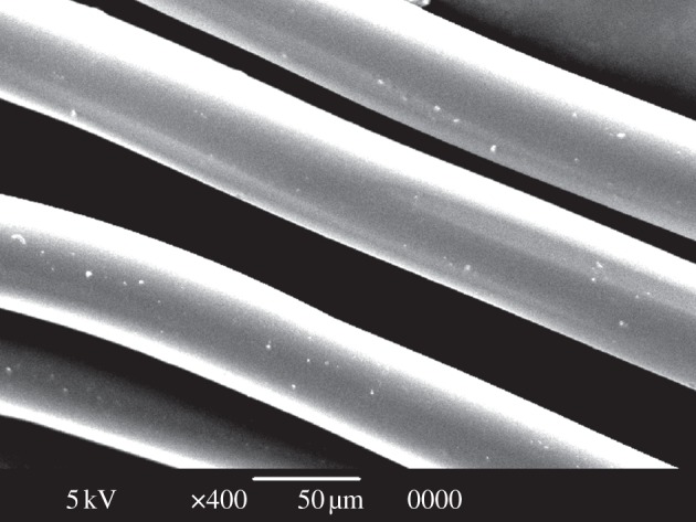
SEM image of the SRF.
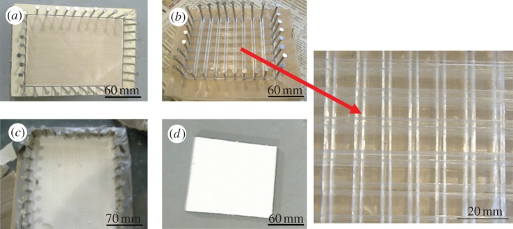
SRF/TP/epoxy composites were fabricated following the flowchart shown in figure 2. Polycaprolactone was chosen as the thermoplastic healing agent because it was reported that it could diffuse and rebond cracked epoxy surfaces with a healing efficiency of about 100 per cent [20,21]. The polycaprolactone (Mn 45 000, Sigma-aldrich) had a melting temperature at around 60°C and density of 1.145 g cm–3. The composites were prepared by a dry weaving process per the pin-guided filament winding process [22]. The spacing between the fibre bundles (ribs) was 13 mm. Epoxy was prepared using bisphenol A diglycidyl ether (Dow Chemical Company, USA) and triethylenetetramine (The Dow Chemical Company). Bisphenol A diglycidyl ether was melted in advance and mixed with TPs by vigorous stirring for 1 h before triethylenetetramine was added. The volume fractions of the TPs and SRF were 12 per cent and 7 per cent, respectively. The mixture was poured into the bay areas of the SRF woven grid skeleton. The composite mixture was degassed in a vacuum oven for 20 min and cured at ambient temperature (22°C) for 40 h. The glass transition temperature of the epoxy matrix was around 75°C.
Figure 2.
Flowchart for fabricating orthogrid SRF grid skeleton/TP/epoxy composites. (a) First, pins were nailed down on a plywood board along the perimeter. A polytetrafluoroethylene sheet was laid on the board for easy de-moulding. (b) The SRF was dry wound around the pins. No resin was applied to the fibres during the weaving process. (c) TP/epoxy mixture was poured into the bay areas of the woven SRF grid skeleton. The composite was degassed and cured. (d) The sample was de-moulded. (Online version in colour.)
3. Characterization
3.1. Characterization of stimuli-responsive fibre
The molecular structure of the SRF was investigated using Fourier transform infrared spectroscopy (FT-IR, Nicholet 6700, Thermo Scientific, USA) equipped with a Smart iTR universal sample holder in the region of 700–4000 cm−1 at room temperature. The thermal properties of the SRFs were investigated using a differential scanning calorimeter (PerkinElmer DSC 4000, USA). The sample was cooled from room temperature to −50°C at a speed of 10°C min−1. Then the sample was scanned from −50 to 240°C at a heating rate of 10°C min−1. The phase separation morphology of the polymer was investigated using an atomic force microscope (AFM, SPA-300HV, Seiko Instruments Inc.) in the tapping-mode under an ambient environment (22 ± 2°C, 45 ± 5% RH). In phase images, a higher modulus material induces a higher phase offset and it appears lighter as opposed to a softer phase, which appears darker. SAXS (small angle X-ray scattering) tests of the fibre were conducted on a Nanostar SAXS machine (Bruker, USA). The X-ray source was copper Kα emission and the wavelength was about 0.154 nm. Samples were scanned in the range of 0.5° ∼ 3.0° (2θ) at a scanning rate of 0.05° min−1. The detector was a Bruker AXS HI-STAR position sensitive area detector. The SAXS was conducted for 1 h on every sample. The model and calculation equations used to calculate the domain structure can be seen in reference [23]. The orientation function of the SRF of the amorphous phase and crystalline phase was determined by IR dichroism using a Perkin-Elmer microscopy (Perkin-Elmer Inc., USA) equipped with a diamond cryogenic Micro-ATR unit and an IR polarizer [24,25]. The calculation methods of the soft and hard segment orientation can be found in references [26,27].
The tensile properties of the SRFs were tested using MTS (mechanical testing and sensing system; Alliance RT/5, MTS Inc., USA) equipped with a 250 N load cell. Sample clamps specified for fibres were used. The crosshead speed was 80 mm min−1 and the gauge length was 38.1 mm (1.5 inch). A toal of 10 specimens were tested. The cross-sectional area of the SRF was obtained using a scanning electron microscope (SEM, JSM-6390, JEOL Ltd., Japan figure 1). The fibres were coated with gold before observation. The damping property tests were conducted using the same MTS (Alliance RT/5, MTS Inc.). One end of the fibre was fixed in the upper clamps of the MTS. The other end of the fibre was hooked with a mass (222.2 g). The initial force exerted by the mass was set to be zero. A 1 N force was applied to the fibre and then released to record the damping properties of the fibres. The elastic fibre was an XLA elastomeric fibre made of cross-linking polyolefin from Aquafil Group, Italy. The supercontraction of the fibre was evaluated by measuring the shrinkage percentage of the free fibre with increasing temperature. The supercontraction ratio of the SRF was determined by the following equation: supercontraction ratio = (L − l)/L × 100%, where L is the original fibre length; l is the length after shrinkage. The supercontraction stress of the SRF was tested using MTS (Qtest/150, MTS Inc., USA) equipment with a thermal chamber (10–162; Thermodynamic Engineering Inc., USA). To determine the thermal-induced supercontraction stress, the fully restrained SRF was heated up from the ambient temperature (25°C) to 170°C at a heating rate of 5°C min−1. The contraction stress of the SRF was recorded. To improve the contraction stress, the second set of samples was cold-drawn with a strain of 150 per cent. The samples were held for 30 min at the strain to partially fix the deformation. Then the strain-hardened fibres were heated so as to test the contraction stress. The experiments were repeated five times.
The cyclic thermomechanical behaviour of the SRF under tension was determined by Instron MTS (Instron Inc., USA). First, the SRF was stretched to 50 per cent elongation ratio at the ambient temperature at a drawing speed of 10 mm min−1. Second, the strain was maintained for 15 min. Third, the upper clamp was returned and the SRF was heated up to 80°C for contraction. Fourth, the SRF was cooled down to ambient temperature. After the cycle was completed, a second cycle began. To study the interface between the SRF and the polymer matrix, the prepared composite was broken in liquid nitrogen to create fracture surface. The interface between the SRF and the polymer was observed using SEM (SEM, JSM-6390, JEOL Ltd., Japan). The fracture surface was coated with gold before SEM observation. Shape memory alloy wires/TP/epoxy composites were also prepared to study the compatibility in comparison with that of SRF/TP/epoxy composite.
3.2. Characterization of the self-healing composite
To demonstrate the self-closure of macro-cracks upon heating, specimens of 8 × 15 × 80 mm3 were cut from the composite panel. A macro-crack was first created on the specimen using the MTS (Qtest 150, MTS Inc., USA) by tension. The crosshead speed was 10 mm min−1. The specimen with the macro-crack was put on a hot plate (CORNG 6795-420D, USA) to trigger the supercontraction of the SRF. A high-resolution charge-coupled device camera (Sony XCD-CR90, Sony Inc., Japan) with a resolution of 3.7 × 3.7 μm/pixel was used to record the closure of the macro-crack. Tapered double-cantilever beam (TDCB) specimens were used to determine the healing efficiency and repeatability of the healing. The specific geometry of the TDCB can be seen in the electronic supplementary material, figure S1a. The healing efficiency was evaluated by tensile test using an MTS Qtest150 machine (MTS Inc., USA) with laboratory-made sample holders (see electronic supplementary material, figure S1b). The protocol for evaluating the self-healing efficiency using the TDCB sample can be seen in reference [28]. The self-healing of the TDCB sample was achieved simply by keeping the cracked TDCB samples in a preheated oven (Gruenberg Model L34HV104 from Lunaire Limited, USA) for 15 min at 80°C (greater than Tg of the SRFs and Tm of the TPs). The oven was power off after 15 min, and the mechanical property tests on the healed samples were conducted after 24 h. The healing efficiency hn was calculated using the equation: hn = (Fo − fn)/fo × 100%, where Fo is the maximum loading of the original sample; fn is the maximum loading of the sample after the nth time of self healing.
4. Results and discussions
4.1. Molecular structure and aggregate structure of the stimuli-responsive fibre
The molecular and aggregate structures of the SRF were studied using differential scanning calorimetry (DSC), atomic force microscope (AFM), small-angle X-ray scattering (SAXS) and Fourier transform infrared spectroscope (FTIR) dichroism. The similarity between SRF and natural spider silks in the primary and aggregate structure is shown in the electronic supplementary material, figure S2. Spider silk molecules are sequences of different long chain amino acids mainly consisting of highly repetitive alanine and glycine blocks [29,30]. The alanine mainly forms the crystalline domains with a dimension of about 2 × 5 × 7 nm. The glycine with larger side-groups forms most of the amorphous phase [30]. The crystalline domains are embedded in the amorphous phase (see electronic supplementary material, figure S2c). The segment assembling into crystalline rigid beta sheet domains can be regarded as the hard segment. The segment forming helical and beta turn amorphous phase can be regarded as the soft segment. The interplay between the crystalline hard region and the soft amorphous region endows spider silks with the extraordinary toughness and strength. The hydrogen bond in spider silks is one of the basic chemical bonds that play a vital role in the mechanical properties of spider silk, as demonstrated by Buehler's research [31–34]. In the spider silk, the hard segment and soft segment are partially orientated.
Like spider silk, the SRP undergoes microphase separation into crystalline phase and amorphous phase, as demonstrated by the DSC results in the electronic supplementary material, figure S3. This is because of the low compatibility of the rich hard segment and the scarce soft segment. The hard segment phase forms crystalline domains that can act as reinforcing nanofillers, stiffening and strengthening the SRF [35]. The phase separation structure of the polymer was observed using AFM, as shown in the electronic supplementary material, figure S4a. The darker areas are indicative of soft segment phase, and lighter areas may represent hard segment phase [36]. The SAXS profile of the SRF with a scattering shoulder in the electronic supplementary material, figure S4b also implies that the SRF is phase separated. The calculated interdomain spacing based on Bragg's Law is 7.95 nm. The abundant hydrogen bonding in the SRF was demonstrated by FTIR (see electronic supplementary material, figure S5). The shift of the stretching vibration of N-H from high wavenumber to low wavenumber indicates the hydrogen bonding between the N–H · · · O=C. The ‘bifurcated’ C=O stretching vibration suggests that the C=O groups are mostly hydrogen bonded [37]. Both the shift of the N–H and C=O stretching vibration to low wavenumbers indicates abundant hydrogen bonding in the SRF. The soft segment and hard segment orientation of the SRF were determined using IR dichroism, as shown in figure 3. The significant differences between the two profiles A// and A⊥ suggest the orientation of the macromolecules in the SRF. The soft segment orientation function was calculated to be 0.19, and the hard segment orientation function was calculated to be 0.56, according to the equations from Siesler et al. [24] and Estes et al. [25].
Figure 3.
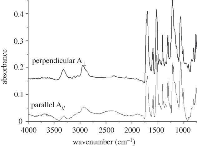
Infrared spectra of the SRF with the polarizer parallel and perpendicular to the fibre direction. The significant differences between A⊥ and A// suggest the orientation of the molecules in the SRF. The soft segment orientation function was calculated to be 0.19; and the hard segment orientation function was calculated to be 0.56.
4.2. Mechanical properties of the stimuli-responsive fibre
Spider silks—in particular, dragline silk—exhibit a unique combination of high tensile strength and extensibility. This enables the unbeatable toughness (area under a stress–strain curve) of spider dragline silks [29,38]. However, because of the difficulty of replicating spider silk proteins and mimicking the exact spinning process of spider silks, the research on fabricating artificial spider dragline silk is not very successful. One of the best achievements to fabricate artificial spider silk is to use recombinant spidroin-like protein to prepare fibre through wet spinning. Elices et al. [39] prepared artificial spider silk recombinant spidroin-1 and spidroin-2 (dragline spider silk) in the major ampullate gland of the spider Nephila clavipes. The maximum mechanical strength of the recombinant spider dragline silks achieved was only one-fifth of natural spider dragline silk [39,40].
Figure 4a shows the tensile properties of the SRF in comparison with natural spider dragline silk (adapted from [41, fig. 1C,D]), recombinant dragline silk (adapted from [39, fig. 2A]), other high-performance fibres (adapted from fig. 2.5, [42]) and steel bar (standard tensile specimen, cold drawn steel 18 (STFC18), cold rolled steel, USA). The tensile strength of the SRF approaches, but is still lower than, that of the spider dragline silk. The tensile strength of the SRF is three times that of the recombinant fibres. Both the tensile strength of the spider dragline silk and the SRF are much higher than that of steel bar.
Figure 4.
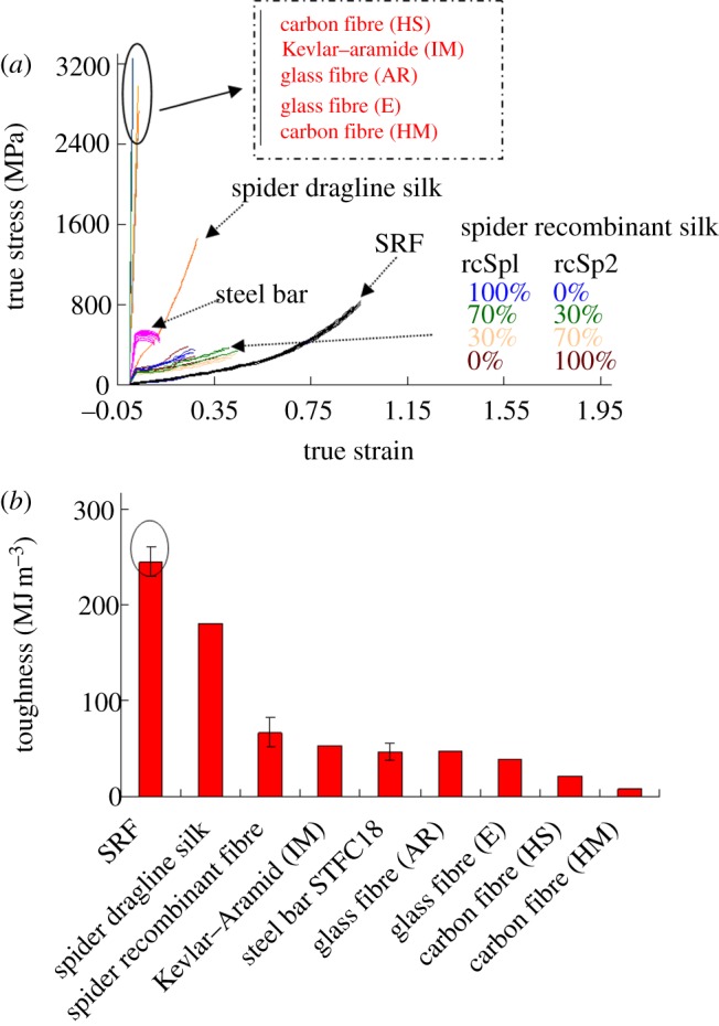
(a) Stress–strain curves of the SRF compared with spider (Araneus major ampullate silk) dragline silk (adapted from Omenetto & Kaplan [41] fig. 1C,D), spider recombinant dragline silk (adapted from Elices et al. [39] fig. 2A), other high performance fibres (adapted from ACI Committee 440 [42] fig. 2.5) and steel bar (STFC18). (The curves and data are intended to indicate relative magnitudes rather than exact values). The mechanical strength of the SRF is approaching though is still lower than that of spider dragline silk. Both the tensile strength of the spider dragline silk and SRF is much higher than that of steel bar. (b) The toughness values of the SRF in comparison with spider dragline silks, Kevlar fibre, spider recombinant dragline silk and other high performance fibres. (Online version in colour.)
Spider silk is the toughest fibre of all the silks and synthetic fibres in existence. Kevlar fibre (aromatic fibre) is the toughest synthetic fibre and has been widely used for ballistic rated body armour fabric and ballistic composites. Figure 4b shows the toughness of the SRF in comparison with spider dragline silk, Kevlar fibre, recombinant dragline silk, other high-performance fibres and a steel bar [41,43]. The SRF has a toughness value of 245 MJ m−3, which is much higher than natural spider dragline silk and Kevlar fibre. It is 1.4 times that of spider dragline silk, four times that of the recombinant fibre, five times that of Kevlar fibre [intermediate modulus (IM)], five times that of steel bar (STFC18), six times that of glass fibre [electrical (E)], 11 times that of carbon fibre [high strength (HS)] and 30 times that of carbon fibre [high modulus (HM)]. Experiments mimicking prey-striking fibres were conducted to demonstrate the outstanding toughness of the SRF (see electronic supplementary material, figure S6). The carbon fibre bundle with a cross-sectional area of 1.8 mm2 was severely damaged, while no damage was found on the SRF bundle with a cross-sectional area of 0.3 mm2. In addition to the outstanding toughness, another crucial issue for spider dragline silk is damping properties that represent how the energy is absorbed if it is impacted. Electronic supplementary material, figure S7 and video S1 show the remarkable damping properties of the SRF when compared with spider dragline silk and elastomeric fibre.
4.3. Stimuli-responsive supercontraction of the stimuli-responsive fibre
A free spider dragline silk shrinks up to 50 per cent in length when wetted. The mechanism is the plasticizing effect of water and disruption of hydrogen bonds in spider silk, leading to the formation of less-organized silk protein [19]. No obvious water-induced supercontraction was observed on the SRF because the SRF is not as hydrophilic as spider silk. The SRF showed thermal-induced supercontraction as a result of its special two-phase structure. During the spinning process, at a temperature above the melting temperature of the crystalline hard segment phase, the fibre is extruded from spinneret. Upon cooling to ambient temperature, the fibre is wound up. The molecules of SRF are slightly oriented resulting from the spinning process. When the SRF is heated up, the soft segments in the amorphous phase have enough mobility. The hydrogen-bonded crystalline hard segment phase has a tendency to contract the fibre, which leads to shrinkage of the fibre. Cold-drawing leads to more alignment of the amorphous phase and thus more supercontraction. Further increasing the temperature leads to the melting of the hard segment phase, which result in the further shrinkage of the SRF.
Figure 5a presents the thermal-induced free supercontraction ratios of the SRFs at different temperatures. Figure 5b shows the contraction stress curves of the restrained SRF. The SRF has a contraction stress of 1.8 MPa. The contraction stress of the SRFs can be improved by strain-hardening through cold-drawing. As shown in figure 5c, after one-time of 100 per cent strain-hardening by cold-drawing, the contraction stress of the SRF reaches 7.8 MPa.
Figure 5.
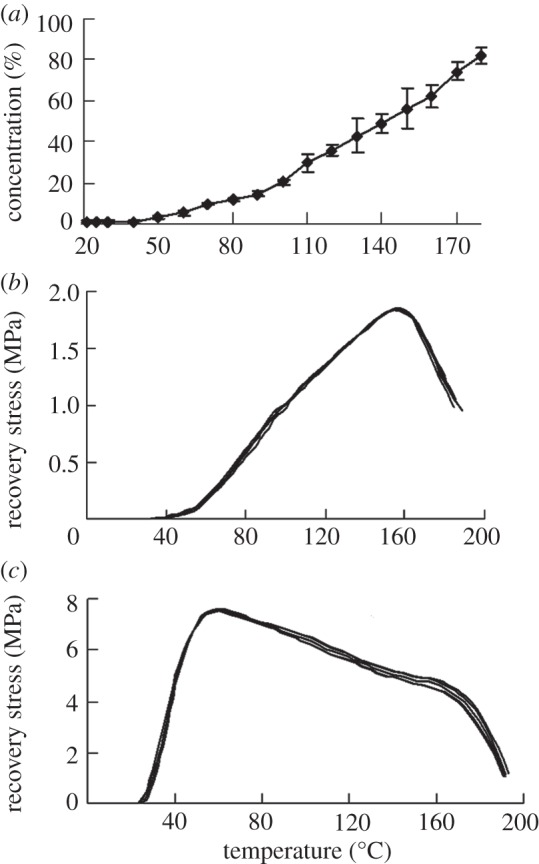
(a) Supercontraction ratio of the SRF at different temperatures. (b) Restrained contraction stress of the as-spun SRF. (c) Restrained contraction stress of the SRF after one-time 100% pre-strain cold-drawing programming.
4.4. Cyclic thermo-mechanical tensile test
Figure 6 shows the cyclic thermo-mechanical tensile testing curves of the SRF. As shown in the figure, if a crack is created in a composite embedded with the SRFs, the fibre will be deformed by stretching (similar to cold-drawing programming). Upon heating, the contraction of the SRF with outstanding mechanical properties may close cracks in the composite by recovering the strain to 0. Furthermore, because the SRF with supercontraction has a tendency to shrink further, the fibre may exert a compressive force on the closed crack interfaces. The cyclic thermo-mechanical cycles are repeatable; therefore, the capability of the SRF to heal macroscopic damages may be repeatable.
Figure 6.
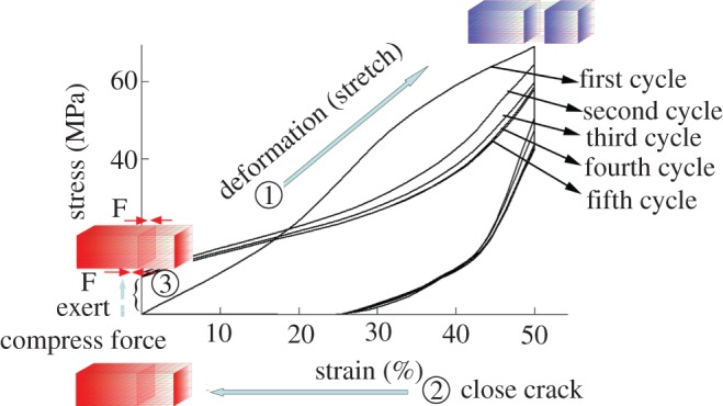
Cyclic thermomechanical tensile curves of the SRF.  If a crack is created in a composite embedded with the SRF, the fibre will be deformed by stretching.
  The contraction of the SRF first closes the macro-cracks in the composite by recovering the strain to 0.
  The SRF with supercontraction has a tendency to shrink further because of the pre-orientation of the amorphous phase during spinning process; therefore, the fibre may exert a compressive force on the closed crack interfaces. The cyclic thermo-mechanical curves are repeatable; the capability of the SRF to heal macroscopic crack may also be repeatable. (Online version in colour.)
4.5. Thermal-induced self-healing of the stimuli-responsive fibre composite
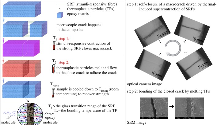
It is expected that the SRFs with the outstanding mechanical properties and thermal-induced supercontraction can close macroscopic cracks if they are embedded in composites. The SRF and TPs were incorporated into a regular epoxy for the self-healing of macroscopic damages. Electronic supplementary material, figure S8 shows the interface between the SRF and polymer matrix in comparison with that of shape memory alloy wire and the polymer matrix. The interface between the SSLF and the matrix is not clear, while the interface between the shape memory alloy wire and the polymer matrix is clear. The shape memory alloy wire is pulled out of the matrix. These results indicate that in comparison with shape memory alloy wire, the SRF has better compatibility with the polymer matrix. Figure 7a shows the schematic self-healing process of the SRF/TP/epoxy composite with a macro-crack. The healing process consists of two-steps. In the first-step, the damaged sample is heated to a temperature (T1) above the glass transition temperature of the SRF to trigger the thermal-induced supercontraction of the SRFs. The supercontraction of the SRFs closes the macro-crack. In the second step, the composite is further heated up to the bonding temperature (T2) of the TPs. The molten TPs flows into the narrowed crack by capillary force, diffuses into the fractured epoxy matrix by concentration gradient and forms physical entanglement and solid wedge when the sample is cooled down. Figure 7b shows the real self-healing process of the composite. In step 1, the damaged sample was put on a hot plate. The macro-crack (3 mm wide) closed within 2 min as a result of the thermal-induced contraction of the SRF (see electronic supplementary material, video S2). In step 2, the composite with the closed/narrowed crack was maintained in an oven preheated to 80°C for 15 min. The molten TPs diffused into the cracked matrix and bridged the crack plane. In addition to direct heating, in future research, conducting fillers or magnetic fillers may be filled into the composites so that the self-healing can be achieved by electric field, alternating magnetic field or infrared light [44,45].
Figure 7.
(a) Schematic of the two-step self-healing process of macroscopic damages in the composites. In the first step, heating the composite to a temperature (T1) above the glass transition temperature of the SRF triggers the supercontraction of the SRF to close the macro-crack (about 3 mm in width). In the second-step, at the bonding temperature (T2), the TPs melt and diffuse into the cracked matrix and bridge the crack plane. (b) The real self-healing process of the composite. In the first-step, the macro-crack is closed by thermal-induced supercontraction of the SRF. In the second-step, the molten TPs flows into the narrowed crack by capillary force, diffuses into the fractured epoxy matrix, and forms solid wedge when the sample is cooled down. (Online version in colour.)
The healing efficiency of the composite was investigated using TDCB specimens, as suggested by Rule et al. [28]. Figure 8a shows the typical load-deflection curves of the original and healed TDCB samples after different fracture/healing cycles, and figure 8b presents the maximum loading of the original and healed TDCB samples after different fracture/healing cycles. According to figure 8b, after the first two-step healing process, 94 per cent of the strength of the sample was recovered. After four rounds of cracking/healing cycles, the healing efficiency can reach 80 per cent. The healing process is reasonably repeatable. ‘To conduct more precise healing efficiency evaluation, the healing efficiency can be further calculated following energy-based approach for proposed by Rule et al. [46].
Figure 8.
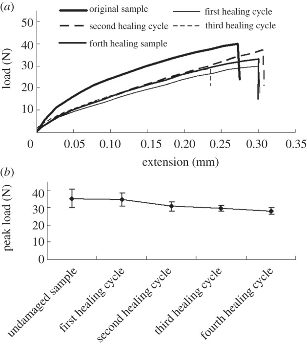
(a) Typical load-displacement curves of the original and healed TDCB samples (after the two-step healing); (b) Maximum loading of the original and healed TDCB samples after different fracture/healing cycles.
5. Conclusions
SRFs with superior mechanical properties and thermal-responsive supercontraction were fabricated for the purpose of healing macroscopic damages in composites. The SRF has superior toughness, which is 1.4 times of spider dragline silk, five times of that Kevlar fibre (IM), six times of that of glass fibre (E), 11 times of that of carbon fibre (HS) and 30 times of that of carbon fibre (HM). SRF-grid-stiffened epoxy composite with embedded TPs was fabricated for healing macroscopic cracks in regular epoxy. Following the two-step biomimetic self-healing scheme, the SRF and TPs healed macroscopic crack in epoxy with a healing efficiency of over 90 per cent. The healing process was also repeatable. It is believed that the SRFs provide a new way to repeatedly, efficiently and molecularly heal macroscopic damages in regular thermosetting polymer composites.
Acknowledgements
This study was sponsored by NASA/EPSCoR under grant no. NASA/LEQSF (2011–14)-Phase3-05 and NSF under grant no. CMMI-0900064. Authors acknowledge Dr Grace W. Namwamba (Agricultural Research & Extension Center, Southern University), Dr Edwin W. Walker (Chemistry Department, Southern University), Ms Lisa Bovenkamp (Center for Advanced Microstructures & Devices, Louisiana State University) and Dr Yoonyoung Jin (Composites CREST Center, Mechanical Engineering Department, Southern University) for their assistance in carrying out mechanical, SEM, SAXS, and SPM studies, respectively.
References
- 1.Blaiszik B. J., Kramer S. L. B., Olugebefola S. C., Moore J. S., Sottos N. R., White S. R. 2010. Self-healing polymers and composites. Annu. Rev. Mater. Res. 40, 179–211 10.1146/annurev-matsci-070909-104532 (doi:10.1146/annurev-matsci-070909-104532) [DOI] [Google Scholar]
- 2.Murphy E. B., Wudl F. 2010. The world of smart healable materials. Progr. Polym. Sci. 35, 223–251 10.1016/j.progpolymsci.2009.10.006 (doi:10.1016/j.progpolymsci.2009.10.006) [DOI] [Google Scholar]
- 3.Syrett J. A., Becer C. R., Haddleton D. M. 2010. Self-healing and self-mendable polymers. Polym. Chem. 1, 978–987 10.1039/c0py00104j (doi:10.1039/c0py00104j) [DOI] [Google Scholar]
- 4.Burattini S., Greenland B. W., Chappell D., Colquhoun H. M., Hayes W. 2010. Healable polymeric materials: a tutorial review. Chem. Soc. Rev. 39, 1973–1985 10.1039/b904502n (doi:10.1039/b904502n) [DOI] [PubMed] [Google Scholar]
- 5.Li G., Nettles D. 2010. Thermomechanical characterization of a shape memory polymer based self-repairing syntactic foam. Polymer 51, 755–762 10.1016/j.polymer.2009.12.002 (doi:10.1016/j.polymer.2009.12.002) [DOI] [Google Scholar]
- 6.Nji J., Li G. 2010. A biomimic shape memory polymer based self-healing particulate composite. Polymer 51, 755–762 10.1016/j.polymer.2009.12.002 (doi:10.1016/j.polymer.2009.12.002) [DOI] [Google Scholar]
- 7.Li G., Uppu N. 2010. Shape memory polymer based self-healing syntactic foam: 3-D confined thermomechanical characterization. Compos. Sci. Technol. 70, 1419–1427 10.1016/j.compscitech.2010.04.026 (doi:10.1016/j.compscitech.2010.04.026) [DOI] [Google Scholar]
- 8.Li G., Xu W. 2011. Thermomechanical behavior of thermoset shape memory polymer programmed by cold-compression: testing and constitutive modeling. J. Mech. Phys. Solids 59, 1231–1250 10.1016/j.jmps.2011.03.001 (doi:10.1016/j.jmps.2011.03.001) [DOI] [Google Scholar]
- 9.Li G., Shojaei A. 2012. A viscoplastic theory of shape memory polymer fibers with application to self-healing materials. Proc. R. Soc. A 468, 2319–2346 10.1098/rspa.2011.0628 (doi:10.1098/rspa.2011.0628) [DOI] [Google Scholar]
- 10.Kirkby E. L., Rule J. D., Michaud V. J., Sottos N. R., White S. R., Manson J.-A. E. 2008. Embedded shape-memory alloy wires for improved performance of self-healing polymers. Adv. Funct. Mater. 18, 2253–2260 10.1002/adfm.200701208 (doi:10.1002/adfm.200701208) [DOI] [Google Scholar]
- 11.Kirkby E. L., Michaud V. J., Mason J. A. E., Sottos N. R., White S. R. 2009. Performance of Self-healing Epoxy with microencapsulated healing agent and shape memory alloy wires. Polymer 50, 5533–5538 10.1016/j.polymer.2009.05.014 (doi:10.1016/j.polymer.2009.05.014) [DOI] [Google Scholar]
- 12.Harmer A. M. T., Blackledge T. A., Madin J. S., Herberstein M. E. 2011. High-performance spider webs: integrating biomechanics, ecology and behaviour. J. R. Soc. Interface 8, 457–471 10.1098/rsif.2010.0454 (doi:10.1098/rsif.2010.0454) [DOI] [PMC free article] [PubMed] [Google Scholar]
- 13.Eisoldt L., Smith A., Scheibel T. 2011. Decoding the secrets of spider silk. Mater. Today 14, 80–86 10.1016/S1369-7021(11)70057-8 (doi:10.1016/S1369-7021(11)70057-8) [DOI] [Google Scholar]
- 14.Buehler M. J., Keten S., Ackbarow T. 2008. Theoretical and computational hierarchical nanomechanics of protein materials: deformation and fracture. Progr. Mater. Sci. 53, 1101–1241 10.1016/j.pmatsci.2008.06.002 (doi:10.1016/j.pmatsci.2008.06.002) [DOI] [Google Scholar]
- 15.Wu X., Liu X. Y., Du N., Xu G., Li B. 2009. Unraveled mechanism in silk engineering: fast reeling induced silk toughening. Appl. Phys. Lett. 95, 093703. 10.1063/1.3216804 (doi:10.1063/1.3216804) [DOI] [Google Scholar]
- 16.Zhou G., Shao Z., Knight D. P., Yan J., Chen X. 2009. Silk fibers extruded artificially from aqueous solutions of regenerated Bombyx mori silk fibroin are tougher than their natural counterparts. Adv. Mater. 21, 366–370 10.1002/adma.200800582 (doi:10.1002/adma.200800582) [DOI] [Google Scholar]
- 17.Bosia F., Buehler M. J., Pugno N. M. 2010. Hierarchical simulations for the design of supertough nanofibers inspired by spider silk. Phys. Rev. E 82, 056103. 10.1103/PhysRevE.82.056103 (doi:10.1103/PhysRevE.82.056103) [DOI] [PubMed] [Google Scholar]
- 18.Agnarsson I., Boutry C., Wong S. C., Baji A., Dhinojwala A., Sensenig A. T., Blackledge T. A. 2009. Supercontraction forces in spider dragline silk depend on hydration rate. Zoology 112, 325–331 10.1016/j.zool.2008.11.003 (doi:10.1016/j.zool.2008.11.003) [DOI] [PubMed] [Google Scholar]
- 19.Boutry C., Blackledge T. 2010. Evolution of supercontraction in spider silk: structure–function relationship from tarantulas to orb-weavers. J. Exp. Biol. 213, 3505–3514 10.1242/jeb.046110 (doi:10.1242/jeb.046110) [DOI] [PubMed] [Google Scholar]
- 20.Rodriguez E. D., Luo X., Mather P. T. 2011. Linear/network poly(ɛ-caprolactone) blends exhibiting shape memory assisted self-healing (SMASH). ACS Appl. Mater. Interfaces 3, 152–161 10.1021/am101012c (doi:10.1021/am101012c) [DOI] [PubMed] [Google Scholar]
- 21.Luo X., Ou R., Eberly D. E., Singhal A., Viratyaporn W., Mather P. T. 2009. A thermoplastic/thermoset blend exhibiting thermal mending and reversible adhesion. ACS Appl. Mater. Interfaces 1, 612–620 10.1021/am8001605 (doi:10.1021/am8001605) [DOI] [PubMed] [Google Scholar]
- 22.Li G., Muthyala V. 2008. Impact characterization of sandwich structures with an integrated orthogrid stiffened syntactic foam core. Compos. Sci. Technol. 68, 2078–2084 10.1016/j.compscitech.2008.03.014 (doi:10.1016/j.compscitech.2008.03.014) [DOI] [Google Scholar]
- 23.Ji F. 2010. Study on the shape memory mechanism of SMPUs and development of high-performance SMPUs. PhD thesis. Kowloon, Hong Kong [Google Scholar]
- 24.Siesler H. W., Holland-Moritz K. 1980. Infrared and Raman spectroscopy of polymers. New York, NY: Marcel Dekker Inc [Google Scholar]
- 25.Estes G. M., Seymour R. W., Cooper S. L. 1971. Infrared studies of segmented polyurethane elastomers. II. Infrared dichroism. Macromolecules 4, 452–457 10.1021/ma60022a018 (doi:10.1021/ma60022a018) [DOI] [Google Scholar]
- 26.Lee H. S., Ko J. H., Song K. S., Choi K. H. 1997. Segmental and chain orientational behavior of spandex fibers. J. Polym. Sci. B Polym. Phys. 35, 1821–1832 (doi:10.1002/(SICI)1099-0488(199708)35:11<1821::AID-POLB13>3.0.CO;2-A) [DOI] [Google Scholar]
- 27.Seymour R. W., Jr, Allegrezza A. E., Cooper S. L. 1973. Segmental orientation studies of block polymers. I. Hydrogen-bonded polyurethanes. Macromolecules 6, 896–902 10.1021/ma60036a021 (doi:10.1021/ma60036a021) [DOI] [Google Scholar]
- 28.Rule J. D., Sottos N. R., White S. R. 2007. Effect of microcapsule size on the performance of self-healing polymers. Polymer 48, 3520–3529 10.1016/j.polymer.2007.04.008 (doi:10.1016/j.polymer.2007.04.008) [DOI] [Google Scholar]
- 29.Lee S. M., Pippel E., Gösele U., Dresbach C., Qin Y., Chandran C. V., Brauniger T., Hause G., Knez M. 2009. Greatly increased toughness of infiltrated spider silk. Science 324, 488–492 10.1126/science.1168162 (doi:10.1126/science.1168162) [DOI] [PubMed] [Google Scholar]
- 30.Gatesy J., Hayashi C., Motriuk D., Woods J., Lewis R. 2001. Extreme diversity, conservation, and convergence of spider silk fibroin sequences. Science 291, 2603–2605 10.1126/science.1057561 (doi:10.1126/science.1057561) [DOI] [PubMed] [Google Scholar]
- 31.Qin Z., Buehler M. J. 2010. Cooperative deformation of hydrogen bonds in beta-strands and beta-sheet nanocrystals. Phys. Rev. E 82, 061906. 10.1103/PhysRevE.82.061906 (doi:10.1103/PhysRevE.82.061906) [DOI] [PubMed] [Google Scholar]
- 32.Keten S., Xu Z., Ihle B., Buehler M. J. 2010. Nanoconfinement controls stiffness, strength and mechanical toughness of beta-sheet crystals in silk. Nat. Mater. 9, 359–367 10.1038/nmat2704 (doi:10.1038/nmat2704) [DOI] [PubMed] [Google Scholar]
- 33.Keten S., Buehler M. J. 2008. Geometric confinement governs the rupture strength of h-bond assemblies at a critical length scale. Nano Lett. 8, 743–748 10.1021/nl0731670 (doi:10.1021/nl0731670) [DOI] [PubMed] [Google Scholar]
- 34.Keten S., Buehler M. J. 2010. Nanostructure and molecular mechanics of spider dragline silk protein assemblies. J. R. Soc. Interface 7, 1709–1721 10.1098/rsif.2010.0149 (doi:10.1098/rsif.2010.0149) [DOI] [PMC free article] [PubMed] [Google Scholar]
- 35.Ji F. L., Hu J. L., Li T. C., Wong Y. W. 2007. Morphology and shape memory effect of segmented polyurethanes. Part I: with crystalline reversible phase. Polymer 48, 5133–5145 10.1016/j.polymer.2007.06.032 (doi:10.1016/j.polymer.2007.06.032) [DOI] [Google Scholar]
- 36.Garrett J. T., Siedlecki C. A., Runt J. 2001. Microdomain morphology of poly(urethane urea) multiblock copolymers. Macromolecules 34, 7066–7070 10.1021/ma0102114 (doi:10.1021/ma0102114) [DOI] [Google Scholar]
- 37.Lin C. K., Kuo J. F., Chen C. Y., Fang J. J. 2012. Investigation of bifurcated hydrogen bonds within the thermotropic liquid crystalline polyurethanes. Polymer 53, 254–258 10.1016/j.polymer.2011.11.009 (doi:10.1016/j.polymer.2011.11.009) [DOI] [Google Scholar]
- 38.Lazaris A., Arcidiacono S., Huang Y., Zhou J.-F., Duguay F., Chretien N., Welsh E. A., Soares J. W., Karatzas C. N. 2002. Spider silk fibers spun from soluble recombinant silk produced in mammalian cells. Science 295, 472–476 10.1126/science.1065780 (doi:10.1126/science.1065780) [DOI] [PubMed] [Google Scholar]
- 39.Elices M., Guinea G. V., Plaza G. R., Karatzas C., Riekel C., Agullo-Rueda F., Daza R., Perez-Rigueiro J. 2011. Bioinspired fibers follow the track of natural spider silk. Macromolecules 44, 1166–1176 10.1021/ma102291m (doi:10.1021/ma102291m) [DOI] [Google Scholar]
- 40.Plaza G. R., et al. 2009. Old silks endowed with new properties. Macromolecules 42, 8977–8982 10.1021/ma9017235 (doi:10.1021/ma9017235) [DOI] [Google Scholar]
- 41.Omenetto F. G., Kaplan D. L. 2010. New opportunities for an ancient material. Science 329, 528–531 10.1126/science.1188936 (doi:10.1126/science.1188936) [DOI] [PMC free article] [PubMed] [Google Scholar]
- 42.440 AC. 1999 ACI Committee 440 1996. State-of-the-art report on fiber reinforced plastic reinforcement for concrete structures, no. 153, pp. 627–628 American Concrete Institute, MI, USA [Google Scholar]
- 43.Gosline J. M., Guerette P. A., Ortlepp C. S., Savage K. N. 1999. The Mechanical design of spider silk: from fiberoin sequence to mechanical function. J. Exp. Biol. 202, 3295–3303 [DOI] [PubMed] [Google Scholar]
- 44.Jung Y. C., Yoo H. J., Kim Y. A., Cho J. W., Endo M. 2010. Electroactive shape memory performance of polyurethane composite having homogeneously dispersed and covalently crosslinked carbon nanotubes. Carbon 48, 1598–1603 10.1016/j.carbon.2009.12.058 (doi:10.1016/j.carbon.2009.12.058) [DOI] [Google Scholar]
- 45.Liu Y., Lv H., Lan X., Leng J., Du S. 2009. Review of Electro-active shape-memory polymer composite. Compos. Sci. Technol. 69, 2064–2068 10.1016/j.compscitech.2008.08.016 (doi:10.1016/j.compscitech.2008.08.016) [DOI] [Google Scholar]
- 46.Rule J. D., Brown E. N., Sottos N. R., White S. R., Moore J. S. 2005. wax-protected catalyst microspheres for efficient self-healing materials. Adv. Mater. 72, 205–208 10.1002/adma.200400607 (doi:10.1002/adma.200400607) [DOI] [Google Scholar]


