Abstract
This paper reports the experimental and theoretical investigation of the Talbot effect beyond the paraxial limit at optical frequencies. Au hole array films with periodicitycomparable to the wavelength of coherent illumination λ were used to study the non-paraxial Talbot effect. Significant differences from the paraxial (classical) Talbot effect were observed. Depending on the ratio of , the interference pattern in the direction perpendicular to the hole array was not necessarily periodic, and the self-image distances deviated from the paraxial Talbot distances. Defects within the hole array film or above the film were healed in the self-images as the light propagated from the surface.
OCIS codes: (110.6760) Talbot and self-imaging effects, (050.1940) Diffraction, (050.6624) Subwavelength structures, (240.6680) Surface plasmons
The Talbot effect is a ubiquitous, lensless self-imaging characteristic of periodic arrays [1]encountered in a range of research areas from atom optics [2] plasmonics [3].Under coherent illumination with wavelength λ at normal incidence, an array with periodicity will form self-images at integer multiples of the Talbot distance [4]. In addition to self-images, patterns with periodicity of can be observed at fractional Talbot distances, where p and q are relative prime numbers [5]. Self-images and fractional images have been used in various applications such as lithography [6], interferometry [7], optical trapping [8], and array illumination [9]. At Talbot distances, self-images of the periodic array can be formed even in the presence of defects; this property has been used to generate defect-free self-images from a defective mask [10].
The self-imaging properties of the Talbot effect, however, are only valid for periodic objects under the paraxial approximation (>>1) [11]. Previous work showed that lateral periodicity was not necessary for achieving longitudinal self-imaging, and certain non-periodic structures could generate self-images [12].Beyond the paraxial limit, the periodicity in the x-y plane is not sufficient to ensure self-imaging in the longitudinal direction. Many applications based on the paraxial Talbot effect, therefore, cannot be extended to nanoscale structures with periodicities comparable to the wavelength of the incident light. Theoretical work has focused on the light patterns from 1D gratings beyond the paraxial limit (the non-paraxial Talbot effect) [5, 13, 14], and some differences in the light patterns were predicted. For example, exact self-images only exist for certain ratios of , and these self-images are expected to appear at positions smaller than Talbot distances. These predicted results, however, have not been confirmed experimentally because of challenges in fabricating large-scale periodic patterns that satisfy and difficulties in imaging the 3D light structure [15]. Recently, the non-paraxial Talbot effect was observed from surface plasmons launched by periodic groves on an Au film [16]; however, the fast damping of surface plasmons limited the study to only the first Talbot distance.
Here we report an experimental and theoretical investigation of the Talbot effect beyond the paraxial limit. We measured and calculated the interference patterns formed by coherent light through hole arrays with on the same order as λ. Different from the paraxial Talbot effect, the self-images were not periodic in the longitudinal direction. In addition, the measured self-image distance was different from the Talbot distance. Our theoretical analysis showed the deviation of fromwas related to the in-phase condition and strongly depended on the ratio . The healing property of the Talbot effect was still observed in the non-paraxial regime. Because of constructive interference of plane waves transmitted through the periodic hole array, defect-free patterns could be observed at even in the presence of defects in the optical path.
Scalar wave theory is traditionally used for the Talbot effect in the paraxial limit, where the light pattern through a periodic hole array at z = 0 (the initial structure) can be represented by a scalar wave ψ and Fourier expanded as a sum of plane waves in the direction of light propagation (z>0) [17]
| (1) |
r = (x, y, z) is the spatial position, λeff = λ/ n is the effective wavelength in the medium with refractive index n, is the complex amplitude of the plane wave, and and are integers. The wave vectorsatisfies and.
In the paraxial limit (a0 >>λeff), Taylor expansion of kz results in
| (2) |
If this approximation is applied to Eq. (1), the following relation can be derived
| (3) |
where is the Talbot distance and s is an integer. Thus, exact self-images will be observed at integer multiples of because the intensities satisfy
Beyond the paraxial limit, however, when approaches unity, the Taylor expansion in Eq. (2) is not valid. The light patterns can still be calculated based on the plane wave summation, but the approximation about kz can no longer be used. To calculate the accurate phase change of the propagating plane waves (the term in Eq. (1)), we consider kz independently for each plane wave beyond the paraxial limit. Since kz is imaginary for evanescent waves with , we therefore simplified the calculation of light patterns in the far field by neglecting the exponentially decaying evanescent waves. Thus, only the propagating plane waves, graphically depicted as points with coordinates inside the circle with radius in k space (Figs. 1(A) –1(B)), are considered. In addition, the condition for achieving exact self-images requires all the plane waves to be in phase at the same distance. If the center frequency is chosen as the reference, this condition can be written as:
| (4) |
for all propagating waves, where is the self-image distance. We divided the non-paraxial Talbot effect into three different regimes based on the number of propagating waves: (i) , (ii) and (iii).
Fig. 1.

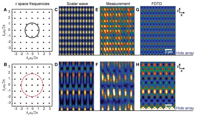
Self-image distances of the non-paraxial Talbot effect are different from the classical Talbot distances. (A-B)Fourier space spectrum of plane waves emitting from the hole array, where the circle with radius a0/λeff separates the propagating waves and evanescent waves. Light patterns from scalar wave calculations with (C) a0/λeff = 1.230 (a0 = 600 nm, λeff = 488 nm), (D)a0/λeff = 1.90 (a0 = 1.2 μm, λeff = 633 nm). Experimental measurement with (E) a0/λeff = 1.230, (F)a0/λeff = 1.90. Light patterns from FDTD simulations with (G) a0/λeff = 1.230, (H)a0/λeff = 1.90.
In regime (i), only the center spatial frequency point in k space can propagate to the far field. Since there are no other plane waves inside the circleto interfere with this center wave, no structured light pattern is observed. In regime (ii), four nearest neighbors are considered when calculating the light pattern in addition to the center spatial frequency (Fig. 1(A)).Because the four nearest neighbors have the same kz component, the self-image distance can be easily derived from Eq. (4):
| (5) |
Equation (5) is similar to the self-image distances for 1D gratings with [13]. In regime (iii), additional plane waves with higher spatial frequencies contribute to the far-field light pattern (Fig. 1(B)). The increased ratio of results in an increase in the number of plane waves that need to be considered in Eq. (4).
We simulated the light patterns at the different regimes above using the scalar wave theory (Figs. 1(C)–1(D)). Since transmission through the hole array is not considered in this model, we assumed that light was uniformly transmitted through the holes and not through the film. In experiment, however, the transmission is enhanced by surface plasmons and depends strongly on the material property and geometry of the structures (Figs. 1(E)–1(F)).For a more accurate calculation and to compare with experiments, we carried out 3D finite difference time domain (FDTD) simulations (Lumerical® software package) .In the FDTD simulations (Figs. 1(G)–1(H)), we used plane wave illumination polarized along the x axis and a uniform mesh of 4 nm. Periodic boundaries were used in the x and y directions and perfectly matched layer (PML) was used in the z direction. The optical constants of Au were taken from Johnson and Christy [18].Since we are only interested in the self-image distances, we only focused on the light patterns on a relative intensity scale; for all figures, yellow represents the strongest intensity.
To compare the light patterns in the three regimes, we used Au square hole arrays with = 600 nm and 1200 nm, and continuous wave laser illumination λeff = 488 nm, 543 nm and 633 nm. Large-area (>1 cm2) Au hole array films with film thicknesses of 130 nm and hole diameters of 150 nm were fabricated using the PEEL technique [19]. Homogenous illumination was obtained by passing the laser light, delivered by an optical fiber, through a collimator. The 3D light patterns generated from the hole arrays were then imaged using a confocal microscope (Nikon® D-Eclipse C1) with z steps of 0.1 μm. The light was collected through a pinhole in the confocal microscope, which removed out of focus light and improved the resolution of the images.
In regime (i) (), we tested the case ( = 600 nm, λeff = 633 nm).As expected, no periodic structure was observed because there was no interference of plane waves (data not shown). In regime (ii) (), we tested (Fig. 1(A)). The corresponding scalar wave simulation showed periodic self-images in the z direction (Fig. 1(C)) that agreed with experiment, where we measured the self-image distances to be 1.2 μm, about 20% less than the Talbot distance μm (Fig. 1(E)). Based on the analytical expression given by Eq. (5), the self-image distance was calculated to be μm, which agreed with the measurement. The light pattern from the FDTD simulation also matched with our measurements (Fig. 1(G)).
In regime (iii) (), self-images satisfying I(x, y, z + zR) = I(x, y, z) can only be observed when the initial structure satisfies certain specific conditions [17]. Although exact self-images do not exist for the periodic hole arrays we used, we found that light patterns at certaindo not deviate significantly from the initial structure. Since these differences are barely distinguishable from noise from experimental misalignment of the light source, we still designate these planes “self-image planes”. For periodic hole arrays with (Fig. 1(B)), we observed three self-images within 10 μm from the film surface in the measurement (Fig. 1(F)): the first self-image appeared at 4 μm, the second at 7.1 μm, and the third at 9.6 μm. Compared to the first and the second self-images, the third self-image was of weaker intensity, and deviations from the initial structure were also more pronounced. The measurement was very different from the paraxial Talbot effect, where the Talbot distance indicates two repeats within 10 μm from the surface of the film with the second repeat at . We note that the measured self-images were not periodic in the longitudinal direction, and the fractional Talbot planes commonly observed in the paraxial Talbot effect were also missing. These differences can be explained by the breakdown of the paraxial approximation, which affects the interference patterns at both the Talbot planes and the fractional Talbot planes. Both scalar wave (Fig. 1(D)) and FDTD simulations (Fig. 1(H)) showed similar self-imaging behavior.
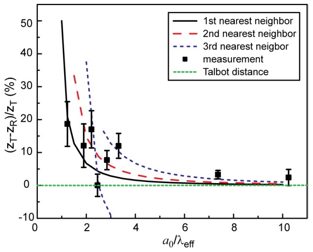
To understand when the self-images distances approach the Talbot distances, we measured the distance of the first self-image for a range of different ratios and plotted its relative difference to as a function of (Fig. 2 ). Our experiments showed that was always smaller than , which is consistent with the Taylor expansion theory that first order expansion of kz gives an upper limit estimation of the self-imaging distance. Since the self-images would form at distances where Eq. (4) was satisfied for all the plane waves simultaneously, we plotted out the solutions for each plane wave (m1, m2). As expected, exact self-images cannot be found because the distances where plane waves are in phase with the reference wave are different for different (m1, m2). At the measured first self-image distances (black squares), deviations from the in-phase conditions caused the light patterns to be different from the initial pattern. These deviations, however, are small enough that the differences in the light pattern are barely distinguishable from the noises in the system. At the Talbot distance (green dotted line), the deviations are much more obvious; therefore, the light patterns at are significantly different from the initial structure. The same analysis can be applied to the second and third self-images. With increasing, all the phase matching curves converged to . We estimate that when, the non-paraxial Talbot effect will approach the paraxial Talbot effect.
Fig. 2.

Difference between the measured first self-image distance zR and the Talbot distance zT is related to a0/λeff. The curves indicate the distances where the 1st, 2nd and 3rd nearest neighbors in k space are in phase with the center spatial frequency and approach the Talbot distance with increasing a0/λeff. At the self-image distances (black squares), the deviations from the phase matching curves are relatively small. The error bars indicate the experimental errors in determining the self-image distances due to the noises.
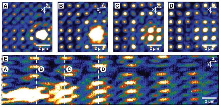
Besides resolving the 3D light pattern from a perfect initial structure, we investigated how the presence of defects would affect the transmitted light pattern. Understanding the impact of defects on the 3D light pattern can potentially benefit applications that rely on the Talbot effect, including lithography and imaging. First, we studied the influence of a 2D defect, a 1.5-µm diameter hole, within the = 1.2µm periodic Au hole array film in regime (iii) with = 2.20. We oversaturated the intensity at the position of the defect so that the light pattern from the hole arrays and the defect could be measured at the same time. When focused to the hole array film (z = 0), the defect appeared as a bright spot approximately 1.5 µm in diameter (Fig. 3(A) ). The presence of the defect resulted in the disappearance of severalsmall bright spots corresponding to the holes in the hole array film. At the first self-image distance, some of the missing holes began to be restored (Fig. 3(B)). At the second (Fig. 3(C)) and third self-image planes (Fig. 3(D)), more missing holes were reconstructed, and the intensity of the defect continuously diminished. This process where defects in the initial structure are healed in the self-images can be seen clearly in the y-z cross-section (Fig. 3(E)).In the presence of the 2D defect, the hole array still generated self-images, and the self-image distances were not affected. Effectively, the defect showed behavior similar to a point source emitting spherical waves, whereas the size of the defect became larger, the intensity decreased in the propagation direction. Light through the defect and the periodic hole array appeared to evolve independently from each other. At self-image planes farther than 10 µm, the influence of the defect became very weak, and defect-free self-images were again observed.
Fig. 3.

2D defects on the film were healed gradually in the self-image planes. Light patterns at self-image distances (A)z = 0 μm, (B)z = 4.4 μm, (C)z = 8.4 μm and (D)z = 13.1 μm. (E) the yz cross-section. As the light propagated in the z direction, the intensity of the defect decreased while the size of the defect increased. (a0 = 1.2 μm, λeff = 543 nm).
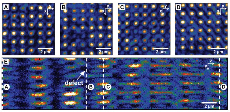
In addition to defects within the hole array film, we studied the influence of 3D defects away from the surface of the film. We used anisotropic Au pyramid particles [19] approximately 3 μm in diameter and embedded them in a uniform poly(dimethylsiloxane) (PDMS) matrix as scattering defects. The pyramids were distributed randomly 11 μm away from the surface of the film. At the film surface (z = 0 µm), we only observed the periodic hole array; the particle was not visible (Fig. 4(A) ). When we focused to z = 11.2 µm (Fig. 4(B)), two bright spots in the light pattern were missing because of scattering by the pyramidal particle. The missing bright spots were restored in the self-images as the light propagated in the z direction, and only one bright spot was missing at the self-image plane 2.3 μm from the particle (Fig. 4(C)). As the propagation distance increased, the periodic pattern was completely restored as if there were no defect in the light path (Fig. 4(D)). In the y-z cross-section, the self-imaging property of the periodic hole array was unchanged, and the influence of the particle was limited to a very local region in the longitudinal direction (Fig. 4(E)).
Fig. 4.

Defect away from the surface of the film was healed in the self-images of the hole array pattern. The light patterns at (A) the film surface z = 0 μm, (B) the position of the particles z = 11.2 μm(C) the self-image planes at z = 13.5 μm and (D) the self-image planes at z = 29 μm. (E) yz cross-section of the 3D light pattern showed the particle had a very local influence on the light pattern. (a0 = 1.2 μm, λ = 543 nm, n = 1.4)
The healing effect observed for the two types of defects can be explained based on the lack of constructive interference of plane waves. Defects and the periodic hole array are composed of plane waves with different spatial frequencies, where the periodic pattern only has plane waves with spatial frequencies k = ().In contrast, finite-size defects can be decomposed into plane waves with many other different spatial frequencies. At the self-image distances, the hole array pattern reappears because plane waves with are in phase and interference constructively. Most of the plane waves composing the defects, however, will have large deviations from the in-phase condition and destructively interfere. With increased propagation distance, deviations from the in-phase conditions become larger, which lead to the gradual disappearance of the defects.
In conclusion, we demonstrated the non-paraxial Talbot effect at optical frequencies. We found that self-images of the initial 2D periodic structure were not necessarily periodic in the longitudinal direction and that phase matching curves could be used to understand and predict changes in the non-paraxial self-image distances compared to the classical Talbot effect. Interestingly, the non-paraxial Talbot effect shared the same healing property as the paraxial Talbot effect. Defects with in the initial hole array structure as well as defects above the film surface were healed in the self-images of the hole array. Although this work was performed at optical frequencies, we anticipate our findings can be applied to other frequency ranges as well as other fields of physics.
Acknowledgments
This work was supported by the NIH-Director’s Pioneer Award ( DP1OD003899). This work made use of the NUANCE Center facilities, supported by NSF-MRSEC, NSF-NSEC and the Keck Foundation and the Center of Nanoscale Materials supported by the US Department of Energy, Office of Basic Energy Sciences (contract no. DE-AC02-06CH11357).
References and links
- 1.M. Masud, Classical Optics and its Applications (Cambridge University Press, 2002), Chap. 18. [Google Scholar]
- 2.Chapman M. S., Ekstrom C. R., Hammond T. D., Schmiedmayer J., Tannian B. E., Wehinger S., Pritchard D. E., “Near-field imaging of atom diffraction gratings—the atomic Talbot effect,” Phys. Rev. A 51(1), R14–R17 (1995). 10.1103/PhysRevA.51.R14 [DOI] [PubMed] [Google Scholar]
- 3.Dennis M. R., Zheludev N. I., García de Abajo F. J., “The plasmon Talbot effect,” Opt. Express 15(15), 9692–9700 (2007). 10.1364/OE.15.009692 [DOI] [PubMed] [Google Scholar]
- 4.Rayleigh L., “On copying diffraction gratings, and on some phenomena connected therewith,” Philos. Mag. 11, 196–205 (1881). [Google Scholar]
- 5.Berry M. V., Klein S., “Integer, fractional and fractal Talbot effects,” J. Mod. Opt. 43(10), 2139–2164 (1996). 10.1080/09500349608232876 [DOI] [Google Scholar]
- 6.Isoyan A., Jiang F., Cheng Y. C., Cerrina F., Wachulak P., Urbanski L., Rocca J., Menoni C., Marconi M., “Talbot lithography: self-imaging of complex structures,” J. Vac. Sci. Technol. B 27(6), 2931–2937 (2009). 10.1116/1.3258144 [DOI] [Google Scholar]
- 7.Nakano Y., Murata K., “Talbot interferometry for measuring the focal length of a lens,” Appl. Opt. 24(19), 3162–3166 (1985). 10.1364/AO.24.003162 [DOI] [PubMed] [Google Scholar]
- 8.Sun Y. Y., Yuan X. C., Ong L. S., Bu J., Zhu S. W., Liu R., “Large-scale optical traps on a chip for optical sorting,” Appl. Phys. Lett. 90(3), 031107 (2007). 10.1063/1.2431768 [DOI] [Google Scholar]
- 9.Lohmann A. W., Thomas J. A., “Making an array illuminator based on the Talbot effect,” Appl. Opt. 29(29), 4337–4340 (1990). 10.1364/AO.29.004337 [DOI] [PubMed] [Google Scholar]
- 10.Dammann H., Groh G., Kock M., “Restoration of faulty images of periodic objects by means of self-imaging,” Appl. Opt. 10(6), 1454–1455 (1971). 10.1364/AO.10.001454 [DOI] [PubMed] [Google Scholar]
- 11.Case W. B., Tomandl M., Deachapunya S., Arndt M., “Realization of optical carpets in the Talbot and Talbot-Lau configurations,” Opt. Express 17(23), 20966–20974 (2009). 10.1364/OE.17.020966 [DOI] [PubMed] [Google Scholar]
- 12.Montgomery W. D., “Self-imaging objects of infinite aperture,” J. Opt. Soc. Am. 57(6), 772–775 (1967). 10.1364/JOSA.57.000772 [DOI] [Google Scholar]
- 13.Noponen E., Turunen J., “Electromagnetic theory of Talbot imaging,” Opt. Commun. 98(1-3), 132–140 (1993). 10.1016/0030-4018(93)90772-W [DOI] [Google Scholar]
- 14.Ring J. D., Lindberg J., Howls C. J., Dennis M. R., “Aberration-like cusped focusing in the post-paraxial Talbot effect,” Opt. Lett. submitted [Google Scholar]
- 15.Chowdhury M. H., Catchmark J. M., Lakowicz J. R., “Imaging three-dimensional light propagation through periodic nanohole arrays using scanning aperture microscopy,” Appl. Phys. Lett. 91(10), 103118 (2007). 10.1063/1.2783177 [DOI] [PMC free article] [PubMed] [Google Scholar]
- 16.Zhang W. W., Zhao C. L., Wang J. Y., Zhang J. S., “An experimental study of the plasmonic Talbot effect,” Opt. Express 17(22), 19757–19762 (2009). 10.1364/OE.17.019757 [DOI] [PubMed] [Google Scholar]
- 17.Saastamoinen T., Tervo J., Vahimaa P., Turunen J., “Exact self-imaging of transversely periodic fields,” J. Opt. Soc. Am. A 21(8), 1424–1429 (2004). 10.1364/JOSAA.21.001424 [DOI] [PubMed] [Google Scholar]
- 18.Johnson P. B., Christy R. W., “Optical-constants of Noble-metals,” Phys. Rev. B 6(12), 4370–4379 (1972). 10.1103/PhysRevB.6.4370 [DOI] [Google Scholar]
- 19.Henzie J., Barton J. E., Stender C. L., Odom T. W., “Large-area nanoscale patterning: chemistry meets fabrication,” Acc. Chem. Res. 39(4), 249–257 (2006). 10.1021/ar050013n [DOI] [PubMed] [Google Scholar]


