

Abstract
Undiluted blood samples are difficult to image in large volumes since blood constitutes a highly absorbing and scattering medium. As a result of this limitation, optical imaging of rare cells (e.g., circulating tumour cells) within unprocessed whole blood remains a challenge, demanding the use of special micro-fluidic technologies. Here we demonstrate a new fluorescent on-chip imaging modality that can rapidly screen large volumes of absorbing and scattering media such as undiluted whole blood samples for detection of fluorescent micro-objects at low concentrations (for example ≤ 50–100 particles/mL). In this high-throughput imaging modality, a large area micro-fluidic device (e.g., 7–18 cm2), which contains for example ~0.3–0.7 mL of undiluted whole blood sample, is directly positioned onto a wide-field opto-electronic sensor-array such that the fluorescent emission within the micro-channel can be detected without the use of any imaging lenses. This micro-fluidic device is then illuminated and laterally scanned with an array of Gaussian excitation spots, which is generated through a spatial light modulator. For each scanning position of this excitation array, a lensfree fluorescent image of the blood sample is captured using the opto-electronic sensor-array, resulting in a sequence of images (e.g., 144 lensfree frames captured in ~36 seconds) for the same sample chip. Digitally merging these lensfree fluorescent images based on a Maximum Intensity Projection (MIP) algorithm enabled us to significantly boost the signal-to-noise ratio (SNR) and contrast of the fluorescent micro-objects within whole blood, which normally remain undetected (i.e., hidden) using conventional uniform excitation schemes, involving plane wave illumination. This high-throughput on-chip imaging platform based on structured excitation could be useful for rare cell research by enabling rapid screening of large volume micro-fluidic devices that process whole blood and other optically dense media.
Introduction
Fluorescent probes and labelling have found wide scale use in various bio-medical assays, bringing specificity and sensitivity to the detection, sensing and imaging tasks of interest1–3. For example, differential labelling of various cell lines is now a routine which enables high-throughput cytometric analysis of cells at e.g., >15 different colours, where each colour represents a unique cell marker or cluster of differentiation4–6. One obstacle that still remains in fluorescent labelling and cytometric analysis of cells is sample preparation since most bodily fluids are optically dense and scattering, making it rather hard to (i) excite fluorescent markers, and (ii) detect their emission since both the excitation and the fluorescence light experience strong extinction within the sample. This is one of the main reasons why fluorescent detection of labelled cells within large volumes of undiluted whole blood is still a major challenge. Due to highly absorbing and scattering nature of whole blood, the height of the micro-fluidic channel that hosts blood cannot be large; and when this limitation is combined with shallow depth-of-field and relatively small field-of-view (FOV) of optical microscopes, the observation volume for undiluted whole blood samples is typically limited to less than 0.2–0.3 μL using conventional microscopy techniques. While mechanical scanning of the objective lens or the micro-fluidic chip that contains the specimen (e.g., blood) could increase this observation volume by capturing multiple images, such a scanning-based conventional microscopy solution would be rather costly and relatively slow since it would necessitate >1,000–2,000 images to be captured for screening a large volume of e.g., >0.3–0.7 mL range, which could easily take more than an hour to scan and digitally process/stitch. To mitigate these challenges, special sample preparation techniques and smart micro-fluidic chips have also been designed that can extract from whole blood samples the target cells of interest with decent specificity and sensitivity, i.e., before scanning and imaging such large area micro-fluidic chips, blood can be entirely flushed out without losing the target cells7–10. Some of these surface-chemistry based approaches also rely on scanning optical microscopes and typically employ >2,000 images to screen the entire active area of the chip7,8 to detect and classify the captured cells of interest across an ultra-wide FOV of e.g., >5–10 cm2.
Here we propose an alternative optical approach for high-throughput fluorescent screening of large volumes of absorbing and scattering media such as whole blood samples. In this on-chip imaging modality (see Figs. 1–2), a large area micro-fluidic chip (with a base area of e.g., 7–18 cm2) is positioned onto a wide-field opto-electronic sensor-array (e.g., a CCD chip), such that the fluorescent emission within an entire sample volume of e.g., 0.3–0.7 mL can be detected without the use of any imaging lenses. This large format micro-fluidic device is then laterally scanned with a 2D array (28 × 21) of Gaussian excitation spots (Fig. 2), which is generated through amplitude modulation on a digital spatial light modulator (SLM). For each position of this excitation array, a lensfree fluorescent image of the sample is captured using the CCD chip, resulting in a sequence of images composed of 144 (12×12) lensfree frames for the same sample. Using a Maximum Intensity Projection (MIP) algorithm11–15, we digitally merge these lensfree fluorescent images to significantly boost the signal-to-noise ratio (SNR) and the contrast of the fluorescent micro-objects within optically dense liquid media, which normally remain undetected and hidden using conventional uniform illumination schemes involving e.g., plane waves.
Fig. 1.

(Left) The experimental set-up of the high-throughput imaging platform, combining structured illumination with lensfree fluorescent on-chip imaging is shown. (Right) An array of excitation spots interacting with the large-area microfluidic chip (~7 cm2), containing an undiluted whole blood sample, is illustrated.
Fig. 2.
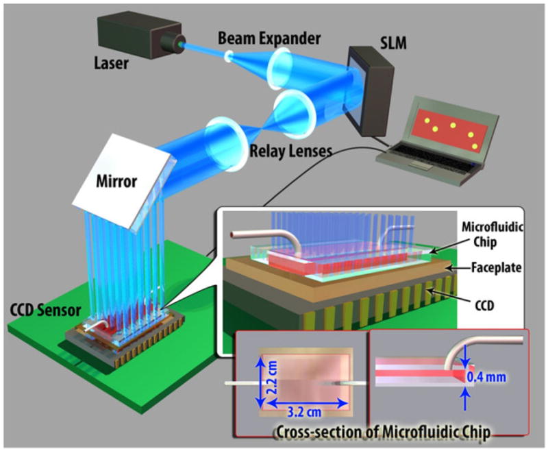
The schematic diagram of the high-throughput fluorescent imaging set-up (not to scale). A structured illumination array is used to excite and laterally scan the fluorescent specimens located within a large-area microfluidic chip (~ 22 × 32 × 0.4 mm). The PC, SLM and the CCD are synchronized using a custom developed LabView interface, rapidly acquiring an entire sequence of 144 lensfree images in ~36 seconds.
We tested the performance of this platform by imaging and counting fluorescent micro-objects within undiluted blood samples, accurately screening a large volume of e.g., ~0.3 mL (i.e., 22 × 32 × 0.4 mm) within <1 minute. This high-throughput on-chip cytometry platform based on an array of Gaussian excitation spots could also be extended to other beam types such as self-healing Bessel beams, which could further improve its performance. In general, this technique might be useful for rare cell research by rapid screening of micro-chips that process large volumes of e.g., blood samples or other optically dense media.
Methods
In our high-throughput fluorescent on-chip imaging platform (Fig. 1), fluorescent micro-objects located within a large area micro-fluidic chip are positioned onto a fiber-optic faceplate (NT55-142, Edmund Optics) that is coupled to a large-format sensor-array (e.g., a CMOS or CCD chip). Faceplate is a planar optical component, consisting of a 2D array of fiber-optic cables that can engineer the point-spread-function of the on-chip imaging system16. The fluorescent objects are excited using structured illumination, which is generated using an SLM. This 2D array of Gaussian excitation spots, after interacting with the fluorescent objects hidden in an optically dense medium, is then rejected using an absorption filter that is coated on the faceplate surface using orasol dyes (Yellow 2RLN, BASF)17. Only the fluorescence emission from these selectively excited objects is collected with the faceplate, and then delivered to the sensor-array without the use of any lenses. After the acquisition of this lensfree fluorescent image of the wide area micro-fluidic chip, the excitation array is shifted in 2D so that 144 (12×12) lensfree fluorescent images are captured using LabView.
Structured Illumination Set-up
To generate the structured excitation/illumination array, we built an experimental setup using an SLM (Holoeye LC-R 2500) as shown in Figs. 1 and 2. In our set-up, a diode laser beam (473 nm, 113 mW, Laserglow: LRS 473-TMF) was initially expanded by a telescopic lens system (~30X magnification) to fill the active area of the SLM. To enable amplitude modulation of the incoming wave, a polarizer and an analyzer were inserted to the beam path before and after the SLM, respectively (not shown in Fig. 2). To cover a large imaging area at the sample plane, e.g., 7–18 cm2, two imaging lenses with focal lengths of 25 cm and 40 cm (BK7, Plano convex lens, Thorlabs) were used to relay the SLM output to the sample FOV with ~1.6X magnification.
In this imaging platform, the entire active area of the SLM (~1024 × 768 pixels, 19 μm pixel size) was used to generate an amplitude modulation mask, which creates an array of 28×21 Gaussian spots. 36×36 pixels of the SLM were assigned to a single Gaussian spot with an aperture function, which can be written as t(x, y) = exp[-(x2 + Y2)/w0], where x and y are the transverse coordinates and w0 is the half beam width at which the field amplitude drops to 1/e value of its peak. We designed our set-up such that half beam width of each Gaussian spot interacting with sample was ~213 μm. Using a custom-developed LabView interface, this array (28×21) of Gaussian beams was laterally scanned by 3 pixel shifts, corresponding to 90 μm step-size at the sample plane. This lateral scanning approach requires 144 (12×12) frames to discretely scan the entire sample area of e.g., 7 cm2 within ~ 36 sec at a modest frame rate of ~4 fps.
On-chip Detection Set-up
Our fluorescent on-chip imaging platform was built on large-format sensor-arrays (e.g., CCD, KAI-11002 and KAF-39000 Sensors, from KODAK) that have very large active areas of e.g., 7–18 cm2. This large active area of the sensor-array is also equivalent to the imaging FOV at the sample plane.16–21
Microfluidic Chip Design
For manufacturing of the microfluidic chips used in this work, a thin (~ 150 μm) cover glass, patterned double-sided adhesive tapes (~ 130 μm thick) and 1 mm thick glass slides were aligned and assembled with a single step process. These micro-fluidic chips have inner dimensions of ~ 22 mm × 32 mm × 0.4 mm that are used to screen large sample volumes of e.g., 0.28 mL on a chip. The same volume can be easily increased to ~ 0.7 mL using a larger FOV CCD sensor (e.g., KAF 39000, Kodak) together with a similar microfluidic chip design as also described in our earlier work18,19.
Sample Preparation
For controlled spiking of the fluorescent micro-particles (10 μm diameter Fluospheres, 505 nm excitation/515 nm emission, F-8836, Invitrogen) into whole blood samples, we pipetted ~ 5 μL of different concentrations of fluorescent bead suspensions into 96 well plates. An initial count of the fluorescent beads in each well was done using a conventional fluorescent microscope, providing a variety of bead counts ranging from as low as 10 to 500 particles per well. Following the drying of the liquid part of the suspension after a few hours, a large volume (~ 0.3 mL) of whole blood sample is loaded into each well of the plate containing only the fluorescent beads suspended in air. After carefully mixing the fluorescent particles and whole blood, the sample is manually injected into our large-volume microfluidic channels, described earlier, using a prefilled syringe. To detect the lost particles during this sample loading step, we then cleaned each used well with ethanol and counted the left-over particles, which were then subtracted from the initial count of the fluorescent beads in each well. We also counted the particles that remained around the edges of the inlet/outlet, which were also subtracted from the final count, yielding us the gold standard fluorescent bead count per micro-fluidic device containing 0.28 mL of undiluted whole blood.
Maximum Intensity Projection (MIP) algorithm
MIP algorithm12,13 is a volumetric projection method that is used to visualize high-intensity voxel values within three-dimensional biological specimens, including computed tomography angiography14 as well as confocal fluorescence microscopy15. While MIP is generally used to render 3D images, in this work it was used to digitally merge the lensfree fluorescent images acquired at each scanning position of the 2D excitation array, detecting the fluorescent objects located in large 3D volumes. In the final fluorescent image that is created based on the MIP algorithm, each pixel of the MIP image contains the maximum value over all the pixel values of the lensfree images captured under structured illumination of the same FOV.
Averaging method
In conventional microscopy, to enhance the SNR of the acquired images, averaging of multiple static frames has been extensively used12. This method adds up a series of static images and divides the sum by the number of images, helping to mitigate different noise sources (e.g., shot-noise and dark-noise)13. We used this conventional averaging method to compare its performance against our MIP based imaging results.
Results and Discussions
We evaluated the performance of our high-throughput on-chip fluorescent imaging platform by rapidly (in ~36 seconds) screening spiked fluorescent particles (~10 μm diameter) within undiluted blood samples injected into large volume (~ 22 mm × 32 mm × 0.4 mm) microfluidic channels (see Figures 3 and 4). In these proof of concept experiments, once the spiked blood samples (see the Methods Section for details) were loaded into our large area microfluidic chips, they were positioned on our imaging platform (Fig. 1) and were excited using (1) uniform plane wave illumination, and (2) structured illumination to compare their performances for accurate counting of the spiked fluorescent micro-particles in whole blood. To provide a fair comparison between structured illumination and uniform plane wave illumination for each spiked blood sample, we captured the same number of lensfree fluorescent frames (i.e., 144) under each excitation scheme. We should also emphasize that to provide a faithful comparison, we equated the maximum value of the SLM mask used to generate the structured illumination with the average value of the mask used to generate the uniform plane wave illumination, so that the excitation intensity per structured Gaussian spot is comparable to the plane wave intensity. Moreover, we also applied both conventional averaging and the MIP algorithm (see the Methods Section) to these 144 frames captured under two different illumination schemes, the results of which are summarized in Fig. 3. As illustrated in Fig. 3 (Top Row), for plane wave illumination, averaging method provided better detection of hidden particles over MIP. This is expected due to the fact that under uniform illumination, the detection SNR is rather low per fluorescent particle within blood and therefore single-frame images (e.g., Fig. 3a) cannot be effectively merged based on high intensity pixels (i.e., the MIP approach). However, for structured illumination (Fig. 3, Bottom Row), MIP approach performed significantly better to recover the hidden fluorescent micro-particles within whole blood (e.g., compare Fig. 3(f) with Figs. 3(b–c,e)) since: (1) the background noise is significantly reduced under structured illumination; and (2) excitation efficiency and uniformity is increased through scanning a Gaussian beam array within an optically dense medium. As expected, averaging method did not work well for structured excitation (Fig. 3(e)) since the illumination was changing over time. Based on these results, structured illumination with MIP algorithm (Fig. 3(f)) had a much better performance over uniform plane wave illumination (Fig. 3, Top Row) for detection of hidden fluorescent micro-particles within a highly absorbing and scattering medium, such as undiluted whole blood.
Fig. 3.

Lensfree fluorescent imaging of spiked fluorescent micro-particles in undiluted whole blood is illustrated using plane wave illumination (PWI) and structured illumination (SI). Multiple frames (N= 144) were captured in both illumination cases. These sequential frames were then digitally merged using either an averaging method or a MIP algorithm as detailed in the Methods Section. (a,d) Single frame lensfree images of both illumination schemes are illustrated, where none of the fluorescent particles can be detected for PWI, whereas a few hidden particles that randomly overlap with the excitation spots are detected under SI. For demonstration purposes, the excitation array of Gaussian beams is overlaid in (d). (b,c) For PWI, averaging based stacking of the lensfree images provided better detection of hidden particles over MIP. SI case is shown in (e,f). A comparison of (f) with (a-c) reveals that SI with MIP algorithm had a much better performance over uniform PWI for detection of hidden fluorescent micro-particles within whole blood.
Fig. 4.
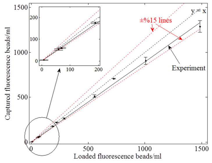
Analysis of the recovery rate of our structured illumination scheme toward detection of hidden fluorescent micro-particles in large volumes of undiluted whole blood. The linear curve consists of 10 points, each of which has 3 different experimental measurements. The overall recovery rate using structured illumination array was ~90%. The inset demonstrates that even very low concentrations (e.g., ~50 particles/mL) can be detected.
To quantify our recovery rate, defined as the ratio of the detected micro-particles to the spiked fluorescent particles within a large blood volume of ~0.3 mL, we performed spiking experiments with different number of fluorescent beads ranging from 50 particles/mL to 1,500 particles/mL (see Fig. 4, where 3 independent measurements were made for each data point). The overall recovery rate of our structured illumination measurements (Fig. 4) is ~90%, whereas the recovery rate for plane wave illumination (after averaging of 144 lensfree frames) is found to be ~50%. These results illustrate the considerably improved performance of our structured illumination scheme for rapid and accurate detection of hidden fluorescent micro-objects in large volumes of optically dense and scattering media.
Note that this technique can also be applied to rapidly screen e.g., milk samples for detection of pathogens at low concentrations. Further, since SLMs have already been integrated even on our cellphones, cost-effective field implementation of this technique should also be feasible. Extension of the same platform to other beam types, such as Bessel beams, could further improve its performance by increasing the excitation efficiency of individual particles/cells through the use of such ‘self-healing’ or ‘self-reconstructing’ beams.22
Conclusions
We demonstrated a high-throughput screening platform, utilizing structured illumination and on-chip fluorescent imaging, to rapidly monitor large volumes of absorbing and scattering media such as undiluted blood samples for rapid and accurate detection of fluorescently labelled micro-objects at low concentrations (e.g., ≤ 50–100 particles/mL). This high-throughput on-chip fluorescent imaging platform based on structured excitation could especially be useful for rare cell research.
Acknowledgments
The support of ARO Young Investigator Award, NSF CAREER Award, NIH Director’s New Innovator Award (DP2), and TUBITAK is acknowledged.
Notes and references
- 1.Shaner NC, Steinbach PA, Tsien RY. Nature Methods. 2005;2:905–909. doi: 10.1038/nmeth819. [DOI] [PubMed] [Google Scholar]
- 2.Zhang J, Campbell RE, Ting AY, Tsien RY. Nature Reviews Molecular Cell Biology. 2002;3:906–918. doi: 10.1038/nrm976. [DOI] [PubMed] [Google Scholar]
- 3.Resch-Genger U, Grabolle M, Cavaliere-Jaricot S, Nitschke R, Nann T. Nature Methods. 2008;5:763–775. doi: 10.1038/nmeth.1248. [DOI] [PubMed] [Google Scholar]
- 4.Rosa SCD, Brenchley JM, Roederer M. Nature Medicine. 2003;9:112–117. doi: 10.1038/nm0103-112. [DOI] [PubMed] [Google Scholar]
- 5.Rosa SCD, Herzenberg LA, Herzenberg LA, Roederer M. Nature Medicine. 2001;7:245–248. doi: 10.1038/84701. [DOI] [PubMed] [Google Scholar]
- 6.Perfetto SP, Chattopadhyay PK, Roederer M. Nature Reviews Immunology. 2004;4:648–655. doi: 10.1038/nri1416. [DOI] [PubMed] [Google Scholar]
- 7.Stott SL, Hsu C-H, Tsukrov DI, Yu M, Miyamoto DT, Waltman BA, Rothenberg SM, Shah AM, Smas ME, Korir GK, Floyd FP, Gilman AJ, Lord JB, Winokur D, Springer S, Irimia D, Nagrath S, Sequist LV, Lee RJ, Isselbacher KJ, Maheswaran S, Haber DA, Toner M. PNAS. 2010 doi: 10.1073/pnas.1012539107. [DOI] [PMC free article] [PubMed] [Google Scholar]
- 8.Nagrath S, Sequist LV, Maheswaran S, Bell DW, Irimia D, Ulkus L, Smith MR, Kwak EL, Digumarthy S, Muzikansky A, Ryan P, Balis UJ, Tompkins RG, Haber DA, Toner M. Nature. 2007;450:1235–1239. doi: 10.1038/nature06385. [DOI] [PMC free article] [PubMed] [Google Scholar]
- 9.Wang S, Wang H, Jiao J, Chen KJ, Owens GE, Kamei K, Sun J, Sherman DJ, Behrenbruch CP, Wu H, Tseng HR. Angewandte Chemie. 2009;121:9132–9135. [Google Scholar]
- 10.Hoshino K, Huang YY, Lane N, Huebschman M, Uhr JW, Frenkel EP, Zhang X. Lab on a Chip. 2011;11:3449–3457. doi: 10.1039/c1lc20270g. [DOI] [PMC free article] [PubMed] [Google Scholar]
- 11.Hammond AT, Glick BS. Traffic. 2000;1:935–940. [PubMed] [Google Scholar]
- 12.Dhawan AP. Medical Image Analysis. John Wiley & Sons; 2011. [Google Scholar]
- 13.White SN. Handbook of Biological Confocal Microscopy. New York: Plenum Press; 1995. [Google Scholar]
- 14.Fishman EK, Ney DR, Heath DG, Corl FM, Horton KM, Johnson PT. Radiographics. 2006;26:905–922. doi: 10.1148/rg.263055186. [DOI] [PubMed] [Google Scholar]
- 15.Harder N, Mora-Bermúdez F, Godinez W, Ellenberg J, Eils R, Rohr K. Medical Image Computing and Computer-Assisted Intervention. Vol. 4190. Springer; 2006. pp. 840–848. [DOI] [PubMed] [Google Scholar]
- 16.Coskun AF, Sencan I, Su TW, Ozcan A. Optics Express. 2010;18:10510–10523. doi: 10.1364/OE.18.010510. [DOI] [PMC free article] [PubMed] [Google Scholar]
- 17.Coskun AF, Sencan I, Su TW, Ozcan A. PLoS ONE. 2011;6:e15955. doi: 10.1371/journal.pone.0015955. [DOI] [PMC free article] [PubMed] [Google Scholar]
- 18.Su TW, Seo S, Erlinger A, Ozcan A. Biotechnology and Bioengineering. 2009;102:856–868. doi: 10.1002/bit.22116. [DOI] [PMC free article] [PubMed] [Google Scholar]
- 19.Seo S, Isikman SO, Sencan I, Mudanyali O, Su TW, Bishara W, Erlinger A, Ozcan A. Anal Chem. 2010;82:4621–4627. doi: 10.1021/ac1007915. [DOI] [PMC free article] [PubMed] [Google Scholar]
- 20.Coskun AF, Su TW, Ozcan A. Lab on a Chip. 2010;10:824–827. doi: 10.1039/b926561a. [DOI] [PMC free article] [PubMed] [Google Scholar]
- 21.Coskun AF, Sencan I, Su TW, Ozcan A. The Analyst. 2011;136:3512–3518. doi: 10.1039/c0an00926a. [DOI] [PMC free article] [PubMed] [Google Scholar]
- 22.Fahrbach FO, Simon P, Rohrbach A. Nature Photonics. 2010;4:780–785. [Google Scholar]