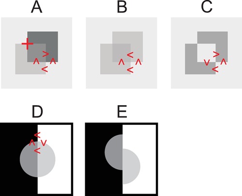
Figure 2.

(a) Single-reversing junction where the lower square is normally seen as transparent and in front of the darker square on the farther surface. The red cross indicates an X-junction. (b) Non-reversing junction where either square may be seen as transparent and in front of the other. (c) Double-reversing junction where no transparency is seen. (d) The disc with X-junctions appears transparent. (e) Shifting the halves of the disc removes the X-junctions and eliminates the perception of transparency. Inequality signs in panels (a) through (d) indicate the luminance relations between adjacent surfaces, oriented in accordance with the corresponding boundary.
