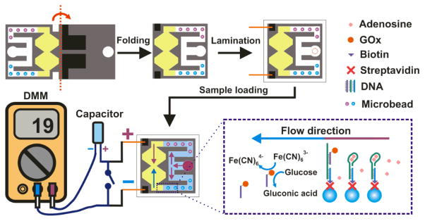
Here we report a self-powered origami paper analytical device (oPAD) that uses an aptamer to recognize an analyte, a glucose oxidase (GOx) tag to modify the relative concentrations of an electroactive redox couple, and a digital multimeter (DMM) to transduce the result of the assay. The sensor is self-powered in that it self-generates an electrical signal so that the read-out process is similar to testing a battery. The principle of the sensor is illustrated in Scheme 1. Briefly, the device is printed on a single piece of paper, folded into a three-dimensional (3D) configuration, and then laminated in plastic. An aliquot of sample is loaded at the inlet, split into two channels, and then directed to microbeads entrapped within the channels. In one channel, an aptamer immobilized on microbeads binds to the target and releases a GOx-labeled DNA strand that flows downstream. No aptamer is present on the microbeads in the other channel, which is used as a control. The split fluids terminate in an hour-glass-shaped, two-compartment electrochemical cell. The waist of the hour glass serves as a salt bridge between the two half cells. In one of the half cells, GOx catalyzes the oxidation of glucose, which in turn results in conversion of Fe(CN)63− to Fe(CN)64−.The difference in concentrations of Fe(CN)63− and Fe(CN)64− in the sensing half cell and control half cell results in a voltage that is used to charge a capacitor. When the switch (lower part of Scheme 1) is closed, the capacitor discharges through the DMM. The capacitor provides a high instantaneous current, in effect an amplified current, and hence a higher sensitivity than a direct current measurement.
Scheme 1.
Schematic illustration showing the operating principle of the sensor.
This device and its operational features are important for five reasons. First, the aptamer is immobilized on microbeads trapped within the paper fluidic channel. This design greatly simplifies probe introduction, compared to direct immobilization on paper,[1] because existing bead immobilization and characterization methods can be used for a range of different probe families including aptamers, DNAzymes,[2, 3] and antibodies. Second, as configured in this device, bead immobilization eliminates the need for a washing step. Third, although aptamers and other nucleic acid probes have been used on test strips,[4] they have not been integrated with fluidic devices using patterned paper. Aptamers can bind to a wide range of targets, including those (like the adenosine target we report) that are not immunogenic.[2] Moreover, nucleic acid probes are generally more stable than those based on proteins.[5] Fourth, the transducer is based on a concentration cell, which acts like a battery to charge a capacitor that is subsequently read-out using a DMM. The latter has a very wide dynamic range, and the use of the capacitor results in a quantitative response that yields a 17-fold enhancement of sensitivity compared to a direct current measurement. Finally, the device is encapsulated in plastic using impulse edge thermal lamination, which solves many problems, including fluid evaporation, reagent deactivation, and device contamination.
Paper fluidics have their genesis in the lateral flow test strip, which was first released commercially by Unipath in 1988 in the form of a home pregnancy test kit.[6] The low cost and ease of use of this family of devices ensured an expansion in the number of types of assays available, particularly for point-of-care applications.[5] In 2007, Whitesides and coworkers added functionality to the basic lateral flow design by developing a means for dividing the paper substrate into hydrophilic and hydrophobic regions.[7] These types of devices are now known as microfluidic paper analytical devices (3PADs).[8–13] In 2008, Whitesides and co-workers introduced 3D PADs, which were constructed by alternating layers of patterned paper and double-sided tape.[14] These devices introduced even more functionality, but the fabrication method does not lend itself to mass production. More recently, we reported an origami-based method that resolves the fabrication problems associated with multilevel μPADs.[15] Origami PADs (oPADs) are fabricated (patterned) on a single sheet of chromatography paper and then folded into a 3D fluidic architecture using simple principles of origami (no adhesive tape or scissors are permitted).
Most paper-based assays transduce the sensing/recognition chemistry using colorimetry,[11, 15] fluorescence,[15] or electrochromism.[16] Therefore image recording using a camera or scanner, a computer, and appropriate software are required for quantification and unambiguous analyte determination.[11, 15] These add time, cost, complexity, and uncertainty (i.e. variation of light) to the assay. Electrochemical methods have also been used to transduce signals from paper-based devices.[9, 17] Such experiments normally involve a potentiostat, which limit applications for POC testing. Handheld readers have alleviated this drawback, and in particular, μPADs have been integrated with personal glucose meters (PGM).[10] However, the sensing chemistry in that case is based on direct oxidation of analytes using the relevant oxidases or dehydrogenases, and the applicability of such sensors to a specific analyte is limited by the availability of the redox enzyme. Note also that the PGM is designed to detect glucose in the millimolar concentration range, and thus requires significant signal amplification for trace analysis.[18]
The second generation oPAD (oPAD 2) reported here is comprised of two layers as shown in Figure 1a. On the first layer, an inlet and a pair of identical channels originating at the inlet, were fabricated by wax printing.[12] On the second layer, two electrodes were fabricated by screen printing conductive carbon ink onto the paper. An additional fluidic inlet is also present on the second layer, and it can be used for adding additional sensing layers in the future. As discussed previously, incorporation of additional sensing layers to the oPADs does not require much fabrication overhead.[15] When the paper is folded at the predefined fold line, the electrodes contact the end of the fluidic channel where the two channels recombine to form two half cells connected by a thin fluidic channel that acts as a salt bridge. This strategy avoids direct printing of the electrodes onto the channel architecture, which would render the channels hydrophobic due to the binder present in the carbon ink.
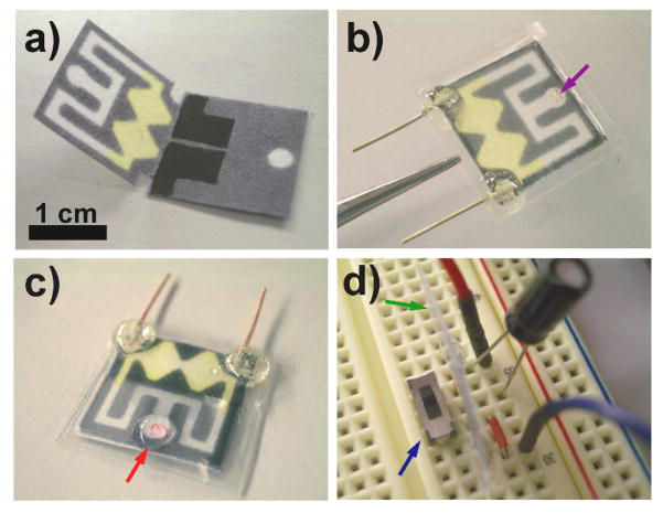
Figure 1.
a) A photograph of the unfolded oPAD fabricated by wax printing on chromatography paper. The two screen-printed carbon electrodes are visible on the bottom layer. The yellow color arises from the presence of Fe(CN)63− preloaded in the channel for the electrochemical assay. b) A photograph of the folded oPAD encapsulated in plastic using thermal edge lamination. The purple arrow indicates an opening for sample introduction, and the two copper wires are for electrical read-out. c) A photograph of the oPAD after introducing a 20 μL sample at the inlet (red arrow). The solution flows into the oPAD and splits into two channels. A movie showing this process is available in the Supporting Information. d) A photograph of a 2.2 μF capacitor, a switch (blue arrow), an oPAD (edge view, green arrow), and jumper wires on a breadboard for measuring the output current of the device using a DMM and simultaneously accumulating charge onto the capacitor.
To test this general approach, we first constructed a concentration cell using the following methodology. GOx was preloaded in one of the channels, and then a solution containing 12 μL of 100 mM glucose and 100 mM Fe(CN)63− in 0.01 M PBS buffer (pH 6.0) was loaded into both halves of the electrochemical cell. After drying in the dark, the device was folded and then encapsulated in plastic by impulse edge thermal lamination. As shown in Figure 1b, the oPAD was fully enclosed with the exception of a small opening for sample loading (marked by a purple arrow) and two copper leads that connected to the carbon electrodes. Note that lamination ensures vertical contact between adjacent layers, which eliminates the need for the type of metal clamp used in our earlier work.[15] After assembly of the oPAD, 20 μL of 0.01 M PBS buffer (pH 7.4) was introduced through the inlet (Figure 1c). After 10 min, when the fluid recombined in the electrochemical cell (Movie 1 in the Supporting Information), the oPAD was placed onto a breadboard, as shown in Figure 1d. The electric circuit on the breadboard was designed to measure the current generated by the oPAD using the DMM while simultaneously accumulating the resulting charge on the capacitor. Of course, in the future, the capacitor would be directly fabricated on paper and integrated into the laminated package. Upon closing the switch, the capacitor quickly discharges, and the resulting maximum current is recorded by the DMM. Information about the sampling frequency of the DMM is provided in the Supporting Information. The important point is that the magnitude of the discharge current increases linearly with increasing concentration of GOx (Figure S1), thereby demonstrating the applicability of the sensor to quantification. Note that making use of the capacitor discharge current increases the sensitivity of the assay by 15.5-fold compared to a simple current measurement (4.1 μA/pmol vs. 0.26 μA/pmol, Figure S1).
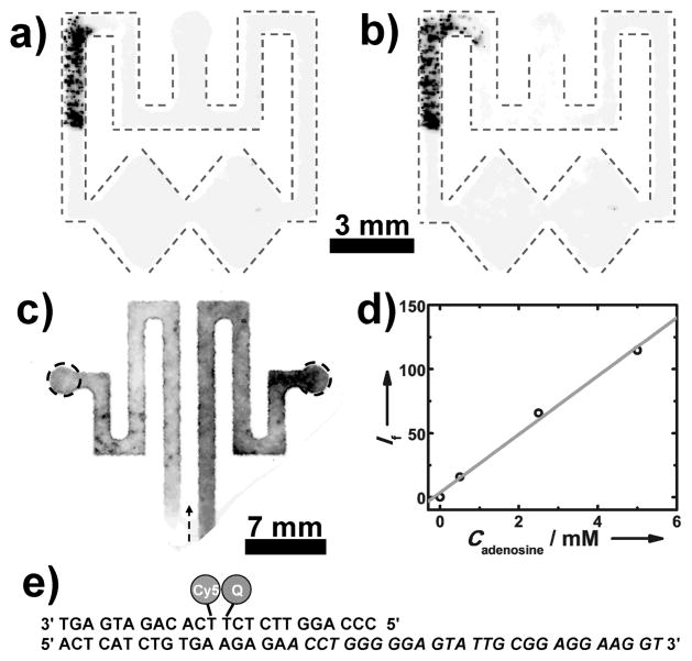
With these promising preliminary results in hand, we carried out a heterogeneous aptamer assay. Biotin-labeled aptamers for adenosine[18, 19] were immobilized on 10 μm-diameter polystyrene (PS) microbeads functionalized on their surface with streptavidin. It was possible to keep track of the location of the microbeads, because they contained fluorescent Nile Red. A 0.10 μL aliquot of the 0.25% (w/v) microbead solution was added to one of the channels and allowed to dry. To ensure that the microbeads did not move in the paper channels, we carried out the following simple experiment. First, the entire unfolded device was imaged in a fluorescence scanner to locate the beads (Figure 2a). Next, the device was folded and a PBS solution (0.01 M, pH 7.4) was added to the device inlet and allowed to flow to its end. Finally, the device was imaged a second time (Figure 2b). The results show minimal (and acceptable) bead displacement after exposure to the buffer solution.
Figure 2.
(Top row) Fluorescent images of the oPAD showing 10 μm fluorescent microbeads preloaded in one split channel a) before and b) after the introduction of 0.01 M PBS buffer (pH 7.4) at the inlet. For clarity, the channels are outlined using dash lines. c) A fluorescence image of a paper fluidic device having two channels preloaded with 15 μL of a solution containing 0.32 μM adenosine aptamer strand, 0.20 μM fluorophore strand, and 0.40 μM quencher strand. The right channel was filled with 15 μL of 0.01 M PBS buffer (pH 7.4)
containing 5 mM adenosine, and the left channel was filled with 15 μL of adenosine-free PBS. The arrow shows the flow direction. The darker color in the right channel represents enhanced fluorescence due to the presence of adenosine. d) A plot of fluorescent intensity (If) versus the concentration of adenosine (Cadenosine) in the sample. The intensity was measured in the right circle shown in c) and subtracted from the intensity measured in the left circle. e) Sequences of aptamer strand, the fluorophore strand, and the quencher strand. The sequence for binding to adenosine is in italics.
Heterogeneous assays generally require longer incubation times than homogeneous assays due to reduced mass transfer of reagents to the immobilized probes. Longer assay times can be a problem for paper devices due to water evaporation, but this issue has been addressed by encapsulating the device in an impermeable enclosure. For example, pressure-sensitive adhesives[11, 13] or printer toner[12] have been used for this purpose. We used a glossy and clear plastic envelope sealed with an impulse thermal edge laminator that only applies heat to the edge of the plastic. This approach avoids adhesives,[11, 13] which can lead to contamination or nonspecific adsorption of reagents or targets, and heat-induced deactivation.[12] Using this approach, we found that the channel stays wet in the enclosed device at 37 °C for > 2 h (Figure S2).
To demonstrate the function of the aptamer probe in the enclosed oPADs, a fluorescent adenosine aptamer sensor (Figure 2e) was tested in the device. Adenosine is a crucial biological cofactor in many biological processes, such as those involved in kidney function. Normal levels of urinary adenosine are in the micromolar range, and elevated renal adenosine levels can be characteristic of disease.[20] As shown in Figure 2c, two separate channels were preloaded with 15 μL of aptamer solution containing 0.32 μM adenosine aptamer strand, 0.20 μM fluorophore strand and 0.40 μM quencher strand, and then the channels were allowed to dry in air. Next, a 15 μL buffer solution containing 5 mM adenosine was introduced into one of the channels, and buffer only was added to the other channel. After 15 min the fluorescence from both channels was measured. As shown in Figure 2c, fluorescence is enhanced in the channel where adenosine is present. Moreover, there is a linear relationship between the fluorescence intensity and the adenosine concentration between 0.5 mM to 5 mM.
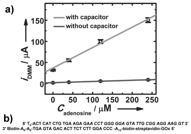
For electrochemical read-out, we used 5′ biotin-modified DNA (bDNA). The biotin group was used to link streptavidin-labeled GOx (sGOx). The sequences are shown in Figure 3b. UV-vis spectroscopy was used to characterize the product. Details about the synthesis, characterization and UV-vis spectra (Figure S3) are available in the Supporting Information. The key point is that bDNA binds to sGOx which is separated from free bDNA by centrifugal filtering. The process for fabricating oPADs for electrochemical detection of adenosine is provided in the Supporting Information. As shown in Figure 3a, the current increased with increasing adenosine concentration. The detection limit, calculated as 3-times the standard deviation of the blank divided by the slope, is 11.8 μM. The sensitivity (0.48 μA/μM) was enhanced by 17-fold compared to that without amplification (0.029 μA/μM).
Figure 3.
a) Calibration curve for detecting adenosine using the oPAD with and without amplification by a capacitor. The error bars represent standard deviation of readings from a DMM for three measurements. b) Sequences of DNA strands of the aptamer sensor. The sequence for binding to adenosine is in italics.
To summarize, we have reported a μPAD-type device that utilizes aptamers as the sensing probe and very simple electrochemical (DMM) read-out. The fabrication of the device is fast, easy, and inexpensive, and all fabrication steps could be easily automated. The sensor is self powered in that it generates a current without the need for an external power source.[21] DMMs are ubiquitous and can be purchased for as little as $US30. Moreover, DMMs integrated with an iPhone or iPod (known as iMultimeter) are now available.[22] Although we used an adenosine aptamer for this proof-of-concept study, a range of probes, including, antibodies, DNAzyme, or aptazymes, could also be integrated into the device using the same sensing platform. We believe the oPAD 2 will prove promising for applications such as point-of-care diagnosis and unambiguous sensing under resource-limited settings.
Supplementary Material
Footnotes
We thank Dr. Bingling Li for DNA characterization. RMC acknowledges sponsorship of this project by the Defense Advanced Research Projects Agency (Contract No. HR0011-12-2-0003) and the Defense Threat Reduction Agency (Contract No. HDTRA1-11-1-0005). The content of the information does not necessarily reflect the position or the policy of the US Government. No official endorsement should be inferred. YL acknowledges support from the National Institutes of Health (ES16865).
Supporting information for this article is available on the WWW under http://www.angewandte.org
Contributor Information
Hong Liu, Department of Chemistry and Biochemistry, Center for Electrochemistry, The University of Texas at Austin, Austin, Texas 78712-0165, United States.
Dr. Yu Xiang, Department of Chemistry, University of Illinois at Urbana-Champaign, Urbana, Illinois 61801, United States
Prof. Yi Lu, Department of Chemistry, University of Illinois at Urbana-Champaign, Urbana, Illinois 61801, United States
Prof. Richard M. Crooks, Email: crooks@cm.utexas.edu, Department of Chemistry and Biochemistry, Center for Electrochemistry, The University of Texas at Austin, Austin, Texas 78712-0165, United States.
References
- 1.Araújo AC, Song YJ, Lundeberg J, Ståhl BL, Brumer H. Anal Chem. 2012;84:3311–3317. doi: 10.1021/ac300025v. [DOI] [PubMed] [Google Scholar]
- 2.Liu JW, Cao ZH, Lu Y. Chem Rev. 2009;109:1948–1998. doi: 10.1021/cr030183i. [DOI] [PMC free article] [PubMed] [Google Scholar]; Cho EJ, Lee JW, Ellington AD. Annual Review of Analytical Chemistry. 2009;2:241–264. doi: 10.1146/annurev.anchem.1.031207.112851. [DOI] [PubMed] [Google Scholar]; Navani NK, Li YF. Curr Opin Chem Biol. 2006;10:272–281. doi: 10.1016/j.cbpa.2006.04.003. [DOI] [PubMed] [Google Scholar]
- 3.Willner I, Shlyahovsky B, Zayats M, Willner B. Chem Soc Rev. 2008;37:1153–1165. doi: 10.1039/b718428j. [DOI] [PubMed] [Google Scholar]; Li D, Song SP, Fan CH. Acc Chem Res. 2010;43:631–641. doi: 10.1021/ar900245u. [DOI] [PubMed] [Google Scholar]; Lubin AA, Plaxco KW. Acc Chem Res. 2010;43:496–505. doi: 10.1021/ar900165x. [DOI] [PMC free article] [PubMed] [Google Scholar]
- 4.Liu JW, Mazumdar D, Lu Y. Angew Chem, Int Ed. 2006;45:7955–7959. doi: 10.1002/anie.200603106. [DOI] [PubMed] [Google Scholar]; Su SX, Ali M, Filipe CDM, Li YF, Pelton R. Biomacromolecules. 2008;9:935–941. doi: 10.1021/bm7013608. [DOI] [PubMed] [Google Scholar]
- 5.Gubala V, Harris LF, Ricco AJ, Tan MX, Williams DE. Anal Chem. 2012;84:487–515. doi: 10.1021/ac2030199. [DOI] [PubMed] [Google Scholar]
- 6.Davies RJ, Eapen SS, Carlisle SJ. Handbook of Biosensors and Biochips. John Wiley & Sons, Ltd; 2008. [Google Scholar]
- 7.Martinez AW, Phillips ST, Butte MJ, Whitesides GM. Angew Chem, Int Ed. 2007;46:1318–1320. doi: 10.1002/anie.200603817. [DOI] [PMC free article] [PubMed] [Google Scholar]
- 8.Martinez AW, Phillips ST, Whitesides GM, Carrilho E. Anal Chem. 2010;82:3–10. doi: 10.1021/ac9013989. [DOI] [PubMed] [Google Scholar]; Lu Y, Shi WW, Jiang L, Qin JH, Lin BC. Electrophoresis. 2009;30:1497–1500. doi: 10.1002/elps.200800563. [DOI] [PubMed] [Google Scholar]; Noh H, Phillips ST. Anal Chem. 2010;82:8071–8078. doi: 10.1021/ac1005537. [DOI] [PubMed] [Google Scholar]; Fu E, Lutz B, Kauffman P, Yager P. Lab Chip. 2010;10:918–920. doi: 10.1039/b919614e. [DOI] [PMC free article] [PubMed] [Google Scholar]; Lutz BR, Trinh P, Ball C, Fu E, Yager P. Lab Chip. 2011;11:4274–4278. doi: 10.1039/c1lc20758j. [DOI] [PMC free article] [PubMed] [Google Scholar]
- 9.Dungchai W, Chailapakul O, Henry CS. Anal Chem. 2009;81:5821–5826. doi: 10.1021/ac9007573. [DOI] [PubMed] [Google Scholar]
- 10.Nie ZH, Deiss F, Liu XY, Akbulut O, Whitesides GM. Lab Chip. 2010;10:3163–3169. doi: 10.1039/c0lc00237b. [DOI] [PMC free article] [PubMed] [Google Scholar]
- 11.Vella SJ, Beattie P, Cademartiri R, Laromaine A, Martinez AW, Phillips ST, Mirica KA, Whitesides GM. Anal Chem. 2012;84:2883–2891. doi: 10.1021/ac203434x. [DOI] [PMC free article] [PubMed] [Google Scholar]
- 12.Schilling KM, Lepore AL, Kurian JA, Martinez AW. Anal Chem. 2012;84:1579–1585. doi: 10.1021/ac202837s. [DOI] [PubMed] [Google Scholar]
- 13.Fenton EM, Mascarenas MR, Lopez GP, Sibbett SS. ACS Appl Mater Interfaces. 2009;1:124–129. doi: 10.1021/am800043z. [DOI] [PubMed] [Google Scholar]
- 14.Martinez AW, Phillips ST, Whitesides GM. Proc Natl Acad Sci U S A. 2008;105:19606–19611. doi: 10.1073/pnas.0810903105. [DOI] [PMC free article] [PubMed] [Google Scholar]
- 15.Liu H, Crooks RM. J Am Chem Soc. 2011;133:17564–17566. doi: 10.1021/ja2071779. [DOI] [PubMed] [Google Scholar]
- 16.Liu H, Crooks RM. Anal Chem. 2012;84:2528–2532. doi: 10.1021/ac203457h. [DOI] [PubMed] [Google Scholar]
- 17.Nie ZH, Nijhuis CA, Gong JL, Chen X, Kumachev A, Martinez AW, Narovlyansky M, Whitesides GM. Lab Chip. 2010;10:477–483. doi: 10.1039/b917150a. [DOI] [PMC free article] [PubMed] [Google Scholar]
- 18.Xiang Y, Lu Y. Nat Chem. 2011;3:697–703. doi: 10.1038/nchem.1092. [DOI] [PMC free article] [PubMed] [Google Scholar]
- 19.Huizenga DE, Szostak JW. Biochemistry. 1995;34:656–665. doi: 10.1021/bi00002a033. [DOI] [PubMed] [Google Scholar]; Nutiu R, Li YF. J Am Chem Soc. 2003;125:4771–4778. doi: 10.1021/ja028962o. [DOI] [PubMed] [Google Scholar]
- 20.Vallon V, Muhlbauer B, Osswald H. Physiol Rev. 2006;86:901–940. doi: 10.1152/physrev.00031.2005. [DOI] [PubMed] [Google Scholar]; Taniai H, Sumi S, Ito T, Ueta A, Ohkubo Y, Togari H. Tohoku J Exp Med. 2006;208:57–63. doi: 10.1620/tjem.208.57. [DOI] [PubMed] [Google Scholar]
- 21.Katz E, Buckmann AF, Willner I. J Am Chem Soc. 2001;123:10752–10753. doi: 10.1021/ja0167102. [DOI] [PubMed] [Google Scholar]
- 22.“iMultimeter” can be found under http://itunes.apple.com/us/app/imultimeter/id420797671?mt=8, 2011
Associated Data
This section collects any data citations, data availability statements, or supplementary materials included in this article.


