Abstract.
Photoacoustic microscopy has achieved submicron lateral resolution, but its axial resolution is much lower. Here an axial resolution of 7.6 μm, the highest axial resolution validated by experimental data, has been achieved by using a commercial 125 MHz ultrasonic transducer for signal detection followed by the Wiener deconvolution for signal processing. Limited by the working distance, the high-frequency ultrasonic transducer can penetrate 1.2 mm into biological tissue from the ultrasound detection side. At this depth, the signal-to-noise ratio decreases by 11 dB, and the axial resolution degrades by 36%. The new system was demonstrated in imaging melanoma cells ex vivo and mouse ears in vivo.
Keywords: photoacoustic microscopy, axial resolution, high-frequency ultrasonic transducer, deconvolution
1. Introduction
Photoacoustic microscopy (PAM) images optical absorption ultrasonically with 100% sensitivity.1 By exciting biomolecules at appropriate optical wavelengths, PAM can provide rich endogenous contrasts in vivo, including hemoglobin, melanin, DNA, RNA, cytochrome, myoglobin, bilirubin, water, and lipid.2–9 In fact, any molecules, which are absorbing at certain wavelengths, can potentially be imaged by PAM. Moreover, PAM has the unique advantage in imaging the functional parameters associated with these biomolecules, such as imaging hemoglobin oxygen saturation, blood flow speed, and temperature variation.10–12 Therefore, label-free PAM is expected to join the mainstream optical microscopy technologies.
Spatial resolution is a key parameter of microscopy. For optical-resolution (OR-) PAM, the lateral resolution, provided by the optical focusing, can be estimated as ,1 where is the optical wavelength and NA is the numerical aperture of the optical objective. Submicron lateral resolution has been achieved for OR-PAM.13,14 The axial resolution, provided by the time-resolved ultrasonic detection, can be estimated, if the impulse response of the ultrasonic transducer has a Gaussian envelope, as (see Appendix), where is the speed of sound and is the ultrasonic transducer bandwidth, which is approximately proportional to the central frequency. Increasing the bandwidth for better axial resolution will decrease the maximum imaging depth, because higher frequency ultrasound attenuates faster in biological tissues. So far, axial resolution for depths up to 1.2 mm has been reported, using the piezoelectric ultrasonic transducer with a 75 MHz central frequency and a 100 MHz bandwidth.15,16 Nevertheless, the axial resolution remains much lower than the lateral resolution in OR-PAM.
Besides piezoelectric ultrasonic transducers, optical sensors have been used for the ultrasonic detection, such as microring resonators17 and Fabry-Perot sensors.18 With broad bandwidth and low noise, microring resonators help achieve an axial resolution of 8 μm,17 which, to the best of our knowledge, is the highest axial resolution achieved so far. However, a microring resonator is unfocused, so, in spite of its high sensitivity to acoustic pressure, it generates images with lower quality than a focused piezoelectric transducer in a confocal arrangement.19 Further, the 8 μm axial resolution has not been demonstrated in biological samples. Moreover, the microring resonator has not been commercialized yet, so it is not readily available to researchers.
The work reported in this paper aims to improve the axial resolution of PAM. By using a commercial 125 MHz ultrasonic transducer for signal detection and the Wiener deconvolution method for signal processing, the axial resolution has reached 7.6 μm, which was experimentally validated. As example applications, we implemented high-axial-resolution imaging of melanoma cells ex vivo and mouse ears in vivo.
2. Methods
2.1. Experimental System
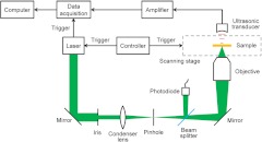
The experimental PAM system is shown in Fig. 1. A tunable OPO laser (NT242-SH, Ekspla) generated laser pulses (5-ns pulse width, 1 kHz pulse repetition rate) with 532-nm wavelength. The laser pulses were spatially filtered by a 50 μm pinhole and then focused by a 0.32-NA objective, providing lateral resolution. The laser pulse intensity was measured by a photodiode (SM05PD1A, Thorlabs) to compensate for the intensity fluctuation. The photoacoustic waves excited by the focused laser pulse were detected by an ultrasonic transducer (125 MHz central frequency, 100 MHz bandwidth, 15 Pa noise equivalent pressure in the 100 MHz bandwidth; V2062, Olympus NDT) with a focusing acoustic lens (NA 0.8). The photoacoustic signals were amplified and digitized at (PCI-5152, National Instruments). The sample was mounted on a scanning stage (PLS-85, MICOS). Both the laser and the scanning stage were triggered by a homemade controller, and the data acquisition card was triggered by the laser output for synchronization. Each time-resolved photoacoustic signal was converted to a 1-D depth-resolved image, and the sample was mechanically scanned in 2-D to generate a three-dimensional (3-D) image.
Fig. 1.
Schematic of the PAM system.
2.2. Signal Processing
To convert each photoacoustic signal to a depth-resolved image, the Hilbert transformation is normally used to extract the envelope of the short-pulsed photoacoustic signal. However, as shown in the literature, deconvolution methods can further improve the axial (depth) resolution.14 Defining the photoacoustic signal from a point target to be the system impulse response, any photoacoustic signal can be approximately modeled as the convolution of the system impulse response and the depth-resolved target function. Deconvolving the photoacoustic signal with the system impulse response exactly recovers the target function under perfect conditions, a linear and shift-invariant system with no noise. In other words, deconvolution recovers the attenuated frequency components of the signal and broadens the system bandwidth, thereby improving the axial resolution. In practice, however, deconvolution is very sensitive to noise, because the frequency components of the signal outside the system passband may be too weak to be recovered in the presence of noise. Therefore, the improvement of axial resolution by using deconvolution is limited, depending on the signal-to-noise ratio (SNR). In this paper, the Wiener deconvolution method20 was used for imaging, and the results were compared with those using the Hilbert transformation method.
3. Results
3.1. System Characterization
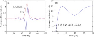
We estimated the axial resolution of the PAM system. The experimental sample was a thin layer of red ink from a whiteboard marker applied to a microscope slide. The photoacoustic waves were excited at the optical focal point on the ink, which worked as a point target for the ultrasonic transducer. The received photoacoustic signal is defined as the system impulse response, as shown in Fig. 2(a). On one hand, the axial resolution can be estimated by the pulse width of the impulse response. The envelope of the impulse response was extracted from the data in Fig. 2(a). The full-width at half-maximum (FWHM) of the envelope is 9 ns, corresponding to 13.5 μm in distance. So the axial resolution is 13.5 μm, which is the size of the image of a point target in the depth direction. This value agrees with that predicted by the axial resolution formula for a Gaussian-enveloped impulse response (see Appendix): . On the other hand, taking into account that the photoacoustic signals from two point targets add in amplitude instead of in envelope, two targets at a separation smaller than 13.5 μm may still be distinguishable in the image. Then the axial resolution can be estimated by numerically shifting and summing two impulse responses in amplitude and checking whether the two peaks can be differentiated in envelope.14 Defining the difference in the photoacoustic envelope between the smaller of the two peaks and the valley to be the contrast,21 the contrast-to-noise ratio (CNR) was plotted versus the shift between the two impulse responses, as shown in Fig. 2(b). The axial resolution, defined as the shift when CNR reaches 6 dB, is 9.5 μm.
Fig. 2.
Estimating the axial resolution of PAM. (a) System impulse response. The full-width at half-maximum (FWHM) of the envelope is 9 ns, corresponding to 13.5 μm in distance. (b) The contrast-to-noise ratio (CNR) versus the shift when summing two impulse responses, as shown in (a).
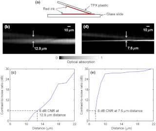
We also designed a novel experiment to measure the axial resolution of the PAM system. As shown in Fig. 3(a), the sample to be imaged consisted of two layers of red ink, one on the polymethylpentene (TPX) plastic and the other on the glass slide. A small angle between the TPX plastic and the glass slide provided continuously variable distance between the two layers. The acoustic impedance of the TPX plastic is close to that of water, so the TPX plastic did not block the ultrasound to be received by the ultrasonic transducer placed on the top. The TPX plastic and the glass slide were coupled with ultrasound gel. A -scan image of the sample calculated by the Hilbert transformation method is shown in Fig. 3(b). Note that the bottom layer of ink appears brighter in the image, because the light illuminates from the bottom. The CNR versus the distance between the two layers is shown in Fig. 3(c). The axial resolution, given by the distance with 6-dB CNR, is 12.9 μm. This is worse than the theoretical estimation given by the shift-and-sum definition (9.5 μm), likely because the top layer has a much weaker amplitude than the bottom layer and is therefore easier to be mixed into the bottom layer in the image.
Fig. 3.
Experimentally measuring the axial resolution of PAM. (a) The sample to be imaged consists of two layers of red ink on polymethylpentene (TPX) plastic (upper) and glass slide (lower), respectively. (b) The -scan image of the sample calculated by the Hilbert transformation method. (c) The CNR versus the distance between the two layers of (b). The axial resolution is 12.9 μm by using the Hilbert transformation. (d) The -scan image of the sample calculated by the deconvolution method. (e) The CNR versus the distance between the two layers of (d). The axial resolution is 7.6 μm by using the deconvolution.
As explained above, the Wiener deconvolution method can be used to improve the axial resolution. The -scan image calculated by the deconvolution method is shown in Fig. 3(d). Both layers appear sharper than those in Fig. 3(b). The axial resolution is 7.6 μm, shown in Fig. 3(e), times better than the result from the Hilbert transformation method. With a higher SNR, we expect to achieve an even better axial resolution. Thus, the deconvolution method was used in the following imaging experiments.
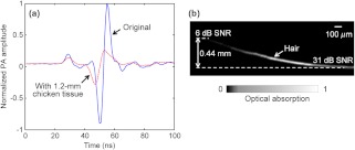
We measured the maximum imaging depths of PAM. To test the penetration capability from the acoustic side, we placed a piece of 1.2-mm-thick chicken tissue between the ink sample and the ultrasonic transducer, whose working distance is 1.2 mm. The system impulse responses, both without and with the 1.2-mm chicken tissue, are shown in Fig. 4(a). With the 1.2-mm chicken tissue in place, the SNR decreases by 11 dB, and the pulse width broadens by 36%. Thus the axial resolution degrades approximately 36% because of the faster attenuation of the high-frequency ultrasound in the 1.2-mm chicken tissue. To test the penetration capability from the optical side, a human hair was inserted obliquely into chicken tissue. As shown in Fig. 4(b), the hair was imaged clearly with an SNR of up to 0.44 mm deep in the tissue. However, deeper penetration is possible by using a lower NA optical objective.19 Therefore, the PAM system can penetrate up to 0.44 mm into soft tissue from the optical side, limited by the SNR, and penetrate up to 1.2 mm from the acoustic side, limited by the working distance.
Fig. 4.
Measuring the maximum imaging depths of PAM from both the acoustic and optical sides. (a) System impulse responses without (blue solid line) and with (red dashed line) 1.2-mm chicken tissue on the acoustic side. (b) A human hair inserted obliquely into chicken tissue from the optical side is imaged clearly up to 0.44 mm in depth.
3.2. High-Axial-Resolution Imaging
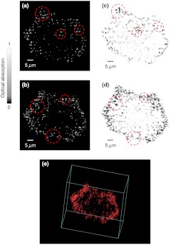
Melanoma cells fixed by formalin were imaged by PAM ex vivo. The cells were seeded onto a slide at a density of . Two cross sections of a cell with 4-µm axial distance are shown in Fig. 5(a) and 5(b). The bright dots in the PAM images are melanosomes, the organelles containing melanin. The PAM images were validated by bright-field optical microscopy (0.75 NA, 20X; FV1000, Olympus), as shown in Fig. 5(c) and 5(d). The PAM image of the melanoma cell is rendered in 3-D as a video in Fig. 5(e).
Fig. 5.
Here the melanosomes can be approximated as point targets, so bright-field optical microscopy can provide 3-D images by depth scanning, though this approach would not work for planar targets.22 Note that PAM generates a 3-D image without depth scanning. In Fig. 5(a)–5(d), the features of interest are indicated by the red dashed circles. The circled features are similar between the PAM and bright-field images, but they do not appear in the adjacent section. However, the difference between the PAM and bright-field images can still be observed, because in practice it is very difficult to take PAM and bright-field images exactly at the same depth and with the same sectioning angle.
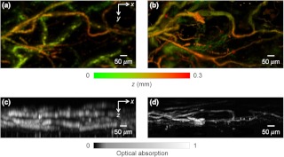
The high-axial-resolution PAM was compared with a PAM system23 with a 50 MHz ultrasonic transducer (90% bandwidth) by imaging mouse ears in vivo. The difference in axial resolution was expected to be times. Both systems worked in transmission mode for a fair comparison. Depth-encoded maximum-amplitude projection (MAP) images of an ear from the two systems are shown in Fig. 6(a) and 6(b). Some blood vessels in the two images appear different, because the light was not focused at exactly the same depth in the ear in the two experiments. The side-view MAP images, as shown in Fig. 6(c) and 6(d), demonstrate the improvement in axial resolution. The high-axial-resolution PAM system with the 125 MHz ultrasonic transducer resolves the blood vessels much more clearly.
Fig. 6.
Comparison of in vivo PAM images of a mouse ear acquired with 50 MHz and 125 MHz ultrasonic transducers. Depth-encoded PAM images acquired with the (a) 50 MHz and (b) 125 MHz ultrasonic transducers. Side-view PAM images acquired with the (c) 50 MHz and (d) 125 MHz ultrasonic transducers.
4. Discussion and Conclusion
Detection sensitivity is a major concern when using a high-frequency ultrasonic transducer. In the in vivo mouse ear imaging experiment, the laser pulse energy was . Assuming the optical focus was 80 μm beneath the skin surface, the surface laser fluence was , well below the American National Standards Institute (ANSI) safety limit of , so the 125 MHz ultrasonic transducer is suitable for in vivo blood vessel imaging. It can be calculated from the results in Fig. 4(a) that the attenuation coefficient of ultrasound in the chicken tissue is . For most soft tissues, the attenuation coefficient is nearly proportional to the acoustic frequency.24 If the central frequency of the ultrasonic transducer is doubled, the acoustic penetration depth will decrease approximately 2 times. Therefore, challenges are expected if we want to further improve the axial resolution by simply using a higher-frequency ultrasonic transducer.
The deconvolution method used to improve the axial resolution has its limitations as well. Deconvolution should be applied to a linear and shift-invariant system. In PAM, as the laser intensity increases, the photoacoustic signal may become nonlinear with the laser intensity due to absorption saturation or nonlinear thermal expansion.25 For oxyhemoglobin, the saturation intensity has been reported to be .25 With the nonlinear effects under such intensity, the deconvolution method may become invalid. In our in vivo experiments, the laser pulse energy is 150 nJ and the pulse width is 5 ns. If the optical focus is 80 μm beneath the skin surface and the extinction coefficient of the tissue is , light will attenuate at the optical focus according to Beer’s law.26 Then the intensity may exceed the saturation intensity within a depth range with the center at the optical focus. Moreover, the shift invariance holds accurately only within the focal zone of the ultrasonic transducer ( here) because the impulse response was measured at the acoustic focus. If a point target is far away from the acoustic focus in the depth direction, the received photoacoustic signal from the target will be quite different from the impulse response from the acoustic focus, causing errors in the deconvolution method. Taking Fig. 3(d) for example, the acoustic focus is approximately located at the bottom ink layer, which may be the major reason why the bottom layer appears thinner than the top layer in the deconvolved image. Here the top layer in Fig. 3(d) should still be located inside the acoustic focal zone, so the thickening of the top layer in the image may also indicate that either deconvolution starts to have error even within the acoustic focal zone or the acoustic focus is in fact slightly below the bottom layer. However, we can measure impulse responses at multiple axial positions and use time-variant-filtering inversion methods to ameliorate this problem.27,28
The acoustic lens for the ultrasonic transducer was made with a large NA of 0.8 in order to increase the solid angle of acoustic detection and thereby the SNR. Here, SNR is critical because the 125 MHz ultrasonic transducer has relatively low detection sensitivity, and high frequency ultrasound attenuates faster in biological tissue. The limitation associated with the high acoustic NA is the small depth of field (), within which the acoustic amplitude degrades times compared with that at the focal point. Outside the acoustic focal zone, the SNR is weaker, and the axial resolution is lower. As shown by the results in Fig. 6(d), we could image blood vessels within a depth range of 150 μm, about 20 times the axial resolutions, with relatively good image quality.
Nonlinear effects in PAM can in fact be another mechanism to provide axial resolution other than the time-resolved ultrasonic detection. For example, two-photon-absorption induced PAM has been reported to achieve an optically determined axial resolution of 45 μm.29 Theoretically, even submicron axial resolution is possible with a high-NA optical objective. However, for this technique, additional depth scanning is required as in two-photon microscopy,30 which dramatically slows down image acquisition. In addition, due to the inefficiency of two-photon absorption at the ANSI-limited laser intensity, the two-photon-absorption signal may be weak.
In conclusion, an axial resolution of 7.6 μm, the finest thus far, has been achieved for PAM. The improved axial resolution benefits PAM in high-resolution 3-D imaging. We are extending the current system to reflection mode14 for applications in more anatomical sites.
Acknowledgments
We thank Prof. James Ballard for the close reading of the manuscript and Dr. Amy Winkler for helpful discussions. This work was sponsored in part by National Institutes of Health (NIH) grants R01 EB000712, R01 EB008085, R01 CA134539, U54 CA136398, R01 CA157277, and R01 CA159959. L.W. has a financial interest in Microphotoacoustics, Inc. and Endra, Inc., which, however, did not support this work. K.M. has a financial interest in Microphotoacoustics, Inc.
Appendix.
Here we derived the axial resolution of PAM, which is limited by the acoustic bandwidth, when the impulse response of the ultrasonic transducer is approximated as a Gaussian-modulated sinusoid:31
| (1) |
where is time, is the amplitude of impulse response, is the transducer central frequency, and , , and are constants. The axial resolution is given by the corresponding distance of the FWHM of the temporal Gaussian envelope:
| (2) |
where is the speed of sound.
The Fourier transformation of is:
| (3) |
where is the angular frequency. The acoustic bandwidth can be approximated by the FWHM of the Gaussian peak of at positive frequency:
| (4) |
Combining Eqs. (2) and (4) leads to:
| (5) |
References
- 1.Wang L. V., Hu S., “Photoacoustic tomography: in vivo imaging from organelles to organs,” Science 335(6075), 1458–1462 (2012). 10.1126/science.1216210 [DOI] [PMC free article] [PubMed] [Google Scholar]
- 2.Zhang H. F., et al. , “Functional photoacoustic microscopy for high-resolution and noninvasive in vivo imaging,” Nat. Biotech. 24(7), 848–851 (2006). 10.1038/nbt1220 [DOI] [PubMed] [Google Scholar]
- 3.Yao D.-K., et al. , “In vivo label-free photoacoustic microscopy of cell nuclei by excitation of DNA and RNA,” Opt. Lett. 35(24), 4139–4141 (2010). 10.1364/OL.35.004139 [DOI] [PMC free article] [PubMed] [Google Scholar]
- 4.Zhang C., et al. , “Label-free photoacoustic microscopy of cytochrome in cells,” Proc. SPIE 8223, 82231W (2012). 10.1117/12.906202 [DOI] [Google Scholar]
- 5.Zhang C., et al. , “Label-free photoacoustic microscopy of myocardial sheet architecture,” J. Biomed. Opt. 17(6), 060506 (2012). 10.1117/1.JBO.17.6.060506 [DOI] [PMC free article] [PubMed] [Google Scholar]
- 6.Zhou Y., et al. , “Photoacoustic microscopy of bilirubin,” J. Biomed. Opt. (submitted). [DOI] [PMC free article] [PubMed] [Google Scholar]
- 7.Xu Z., Zhu Q., Wang L. V., “In vivo photoacoustic tomography of mouse cerebral edema induced by cold injury,” J. Biomed. Opt. 16(6), 066020 (2011). 10.1117/1.3584847 [DOI] [PMC free article] [PubMed] [Google Scholar]
- 8.Wang H.-W., et al. , “Label-free bond-selective imaging by listening to vibrationally excited molecules,” Phy. Rev. Lett. 106(23), 238106 (2011). 10.1103/PhysRevLett.106.238106 [DOI] [PMC free article] [PubMed] [Google Scholar]
- 9.Allen T. J., et al. , “Spectroscopic photoacoustic imaging of lipid-rich plaques in the human aorta in the 740 to 1400 nm wavelength range,” J. Biomed. Opt. 17(6), 061209 (2012). 10.1117/1.JBO.17.6.061209 [DOI] [PubMed] [Google Scholar]
- 10.Yao J., et al. , “Label-free oxygen-metabolic photoacoustic microscopy in vivo,” J. Biomed. Opt. 16(7), 076003 (2011). 10.1117/1.3594786 [DOI] [PMC free article] [PubMed] [Google Scholar]
- 11.Wang Y., Maslov K., Wang L. V., “Spectrally encoded photoacoustic microscopy using a digital mirror device,” J. Biomed. Opt. 17(6), 066020 (2012). 10.1117/1.JBO.17.6.066020 [DOI] [PMC free article] [PubMed] [Google Scholar]
- 12.Shah J., et al. , “Photoacoustic imaging and temperature measurement for photothermal cancer therapy,” J. Biomed. Opt. 13(3), 034024 (2008). 10.1117/1.2940362 [DOI] [PMC free article] [PubMed] [Google Scholar]
- 13.Zhang C., Maslov K., Wang L. V., “Subwavelength-resolution label-free photoacoustic microscopy of optical absorption in vivo,” Opt. Lett. 35(19), 3195–3197 (2010). 10.1364/OL.35.003195 [DOI] [PMC free article] [PubMed] [Google Scholar]
- 14.Zhang C., et al. , “Reflection-mode submicron-resolution in vivo photoacoustic microscopy,” J. Biomed. Opt. 17(2), 020501 (2012). 10.1117/1.JBO.17.2.020501 [DOI] [PMC free article] [PubMed] [Google Scholar]
- 15.Wang L., et al. , “Fast voice-coil scanning optical-resolution photoacoustic microscopy,” Opt. Lett. 36(2), 139–141 (2011). 10.1364/OL.36.000139 [DOI] [PMC free article] [PubMed] [Google Scholar]
- 16.Wang Y., et al. , “Integrated photoacoustic and fluorescence confocal microscopy,” IEEE Trans. Biomed. Eng. 57(10), 2576–2578 (2010). 10.1109/TBME.2010.2059026 [DOI] [PMC free article] [PubMed] [Google Scholar]
- 17.Xie Z., et al. , “Pure optical photoacoustic microscopy,” Opt. Express 19(10), 9027–9034 (2011). 10.1364/OE.19.009027 [DOI] [PMC free article] [PubMed] [Google Scholar]
- 18.Zhang E. Z., et al. , “Multimodal photoacoustic and optical coherence tomography scanner using an all optical detection scheme for 3-D morphological skin imaging,” Biomed. Opt. Express 2(8), 2202–2215 (2011). 10.1364/BOE.2.002202 [DOI] [PMC free article] [PubMed] [Google Scholar]
- 19.Hu S., Maslov K., Wang L. V., “Second-generation optical-resolution photoacoustic microscopy with improved sensitivity and speed,” Opt. Lett. 36(7), 1134–1136 (2011). 10.1364/OL.36.001134 [DOI] [PMC free article] [PubMed] [Google Scholar]
- 20.Jensen J. A., et al. , “Deconvolution of in-vivo ultrasound -mode images,” Ultrason. Imag. 15(2), 122–133 (1993). 10.1006/uimg.1993.1010 [DOI] [PubMed] [Google Scholar]
- 21.Ku G., et al. , “Photoacoustic microscopy with 2-µm transverse resolution,” J. Biomed. Opt. 15(2), 021302 (2010). 10.1117/1.3339912 [DOI] [PMC free article] [PubMed] [Google Scholar]
- 22.Wang L. V., Wu H.-I., Biomedical Optics: Principles and Imaging, Wiley, Hoboken, New Jersey, pp. 164–169 (2007). [Google Scholar]
- 23.Yao J., et al. , “Double-illumination photoacoustic microscopy,” Opt. Lett. 37(4), 659–662 (2012). 10.1364/OL.37.000659 [DOI] [PMC free article] [PubMed] [Google Scholar]
- 24.Wells P. T., Biomedical Ultrasonics, pp. 120–123, Academic Press, New York: (1977). [Google Scholar]
- 25.Danielli A., et al. , “Picosecond absorption relaxation measured with nanosecond laser photoacoustics,” Appl. Phys. Lett. 97(16), 163701 (2010). 10.1063/1.3500820 [DOI] [PMC free article] [PubMed] [Google Scholar]
- 26.Liu Y., Zhang C., Wang L. V., “Effects of light scattering on optical-resolution photoacoustic microscopy,” J. Biomed. Opt. (submitted). [DOI] [PMC free article] [PubMed] [Google Scholar]
- 27.Phoong S.-M., Vaidyanathan P. P., “Time-varying filters and filter banks: some basic principles,” IEEE Trans. Signal Process. 44(12), 2971–2987 (1996). 10.1109/78.553472 [DOI] [Google Scholar]
- 28.Wang G., “The most general time-varying filter bank and time-varying lapped transforms,” IEEE Trans. Signal Process. 54(10), 3775–3789 (2006). 10.1109/TSP.2006.879311 [DOI] [Google Scholar]
- 29.Yamaoka Y., Nambu M., Takamatsu T., “Fine depth resolution of two-photon absorption-induced photoacoustic microscopy using low-frequency bandpass filtering,” Opt. Express 19(14), 13365–13377 (2011). 10.1364/OE.19.013365 [DOI] [PubMed] [Google Scholar]
- 30.Helmchen F., Denk W., “Deep tissue two-photon microscopy,” Nat. Methods 2(12), 932–940 (2005). 10.1038/nmeth818 [DOI] [PubMed] [Google Scholar]
- 31.Insana M. F., Cook L. T., “Bioelasticity imaging: system design,” Proc. SPIE 3659, 224–235 (1999). 10.1117/12.349497 [DOI] [Google Scholar]
Associated Data
This section collects any data citations, data availability statements, or supplementary materials included in this article.


