Abstract
The Dynesys, a flexible posterior stabilization system that provides an alternative to fusion, is designed to preserve intersegmental kinematics and alleviate loading at the facet joints. Recent biomechanical evidence suggests that the overall range of motion (ROM) with the Dynesys is less than the intact spine. The purpose of this investigation was to conduct a comprehensive characterization of the three-dimensional kinematic behaviour of the Dynesys and determine if the length of the Dynesys polymer spacer contributes to differences in the kinematic behaviour at the implanted level. Ten cadaveric lumbar spine segments (L2–L5) were tested by applying a pure moment of ±7.5 Nm in flexion–extension, lateral bending, and axial rotation, with and without a follower preload of 600 N. Test conditions included: (a) intact; (b) injury; (c) injury stabilized with Dynesys at L3–L4 (standard spacer); (d) long spacer (+2 mm); and (e) short spacer (−2 mm). Intervertebral rotations were measured using an optoelectronic camera system. The intersegmental range of motion (ROM), neutral zone (NZ), and three-dimensional helical axis of motion (HAM) were calculated. Statistical significance of changes in ROM, NZ, and HAM was determined using repeated measures analysis of variance (ANOVA) and Student–Newman–Keuls post-hoc analysis with P<0.05. Implantation of the standard length Dynesys significantly reduced ROM compared to the intact and injured specimens, with the least significant changes seen in axial rotation. Injury typically increased the NZ, but implantation of the Dynesys restored the NZ to a magnitude less that that of the intact spine. The Dynesys produced a significant posterior shift in the HAM in flexion–extension and axial rotation. The spacer length had a significant effect on ROM with the long spacer resulting in the largest ROM in all loading directions without a follower preload. The largest differences were in axial rotation. A 4 mm increase in spacer length led to an average intersegmental motion increase of 30% in axial rotation, 23% in extension, 14% in flexion, and 11% in lateral bending. There were no significant changes in NZ with different spacer lengths. Typically, the short spacer caused a greater shift and a greater change in orientation of the HAM than the long spacer. The long spacer resulted in a ROM and a motion pattern, as represented by the HAM, that was closer to that seen in an intact specimen. The results of this study suggest that the length of the Dynesys spacer altered the segmental position and therefore affected kinematic behaviour.
Keywords: Biomechanics, Lumbar spine, Non-fusion, Stabilization, Surgical treatment
Introduction
At some point in life, 70–85% of people will experience low back pain [1, 11]. While not all individuals will require a surgical treatment, the number of surgeries performed for chronic low back pain is constantly increasing [1]. Spinal fusion, which aims to eliminate motion at the joint, is considered by some to be the standard surgical intervention for chronic low back pain treatment and it has been shown to be more effective than conservative care [4]. It has been suggested that fusion may actually accelerate degeneration at adjacent levels [2, 9, 19], so alternative treatments may be advantageous.
Dynamic posterior stabilization is an alternative to fusion for the treatment of degenerative problems in the lumbar spine. The Dynesys dynamic neutralization system (Zimmer GmbH, Winterthur, Switzerland) is one such system that is designed to preserve the intersegmental kinematics and reduce loading at the facet joints. The Dynesys is a bilateral device that consists of titanium alloy pedicle screws and polycarbonate urethane (PCU) spacers that surround tensioned polyethylene terephthalate (PET) cords (Fig. 1). The spacers withstand compressive loads, while the tensioned cords stabilize the system and act against tensile loads as well as flexion moments. Presumably, the length of the spacer is an important parameter that directly influences both intersegmental motion and loading, since it determines the segmental position (disc height, facet joint position, and tension of the ligaments).
Fig. 1.
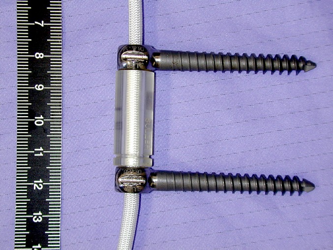
Dynesys polycarbonate urethane (PCU) spacer surrounding tensioned polyethylene terephthalate (PET) cord between titanium alloy pedicle screws
A biomechanical evaluation of the Dynesys system by Freudiger et al. [3] in 1999 found that in flexion–extension, the Dynesys significantly restricted rotation, but increased the axial translation. In 2002, the first multi-centre clinical study showed that the Dynesys was a safe and effective procedure for the stabilization of the lumbar spine in 83 patients, with the greatest complication being the loosening of the pedicle screw [21]. A recent biomechanical study by Schmoelz et al. [20] found that the Dynesys was more flexible than pedicle fixation in all three primary loading directions, but in general was a lot stiffer than the intact spine. After injury, in lateral bending and flexion, the Dynesys restored the neutral zone (NZ), which represents the low stiffness behaviour of the spine, to a magnitude below that seen in an intact specimen. The effects of variation in spacer length were not investigated in any of these studies.
These biomechanical studies analysed the kinematic behaviour using intersegmental translations and/or rotations about a primary axis. Neither study included helical axis of motion (HAM) as a measure of kinematics [3, 20]. The HAM is the unique axis about which a body rotates and parallel to which it translates [14]. In addition to the range of motion (ROM), the HAM describes the motion pattern of the spine, which is important for the analysis of non-fusion spinal implants.
Due to the increasing clinical use and lack of important biomechanical data with respect to the Dynesys system, we embarked on this study. The purpose of this investigation was to conduct a three-dimensional kinematic evaluation of the Dynesys system and to determine if the length of the Dynesys spacer contributes to differences in the kinematic behaviour at the implanted level.
Materials and methods
Ten fresh frozen cadaveric lumbar spine segments from L2–L5 were tested. The age of the specimens ranged from 70 to 88 years with an average age of 77.2 years and consisted of six males, three females, and one unknown gender. The spines were prepared by dissecting the musculature, while preserving the soft tissue. The L2 and L5 vertebrae were potted in dental stone mounts such that the L3–L4 disc space remained horizontal.
Three-dimensional flexibility tests were conducted on each of the specimens under five different conditions:
Intact
Injury
Dynesys implant at L3–L4 (standard length spacer)
Dynesys implant at L3–L4 (long spacer)
Dynesys implant at L3–L4 (short spacer)
The testing order of conditions (3)–(5) was randomized to eliminate the variability due to the test sequence.
A custom designed and fabricated spine testing machine was used to apply a maximum pure moment of ±7.5 Nm to the top vertebra, while the specimen was allowed to move in an unconstrained three-dimensional fashion (Fig. 2) [7]. This continuous moment was applied at a rate of approximately 1.3°/s in all the three primary directions of loading, namely flexion–extension, lateral bending, and axial rotation. The load was applied for three completely reversed loading cycles.
Fig. 2.
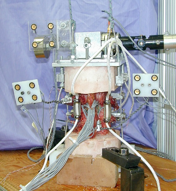
Test set-up. Looking at the posterior aspect of the specimen with the implanted Dynesys (see reference [7] for details)
All the tests were conducted with and without the presence of a compressive follower preload of 600 N. The purpose of a follower preload was to simulate physiologic compressive loading in an in vitro spine study [16]. The path of the follower preload followed the contour of the specimen such that each segment was subjected to a nearly pure compressive load. The path was optimized in the neutral position so that the application of the compressive preload did not create a significant rotation in the sagittal plane. The follower preload was applied prior to and held through the duration of the flexibility test. The purpose of including a testing without a follower preload was to allow a comparison with studies in which no follower preload was used and with historical data.
Before Dynesys insertion, an injury at L3–L4 was created to simulate instability in the specimen. The injury involved sectioning of the facet joint capsules, sectioning of the posterior ligaments (supraspinous and interspinous), and a posterolateral nucleotomy. This injury was chosen because it was reproducible, allowed examination of the stabilizing capability of the Dynesys, and was consistent with injury models in the literature [20].
The Dynesys was installed using the manufacturer’s recommended operative procedure and supplied tools. The pedicle screws were inserted into the L3 and L4 pedicles (lateral pedicle insertion technique) and cemented in place using polymethylmethacrylate (PMMA) to ensure that there was no loosening at the bone–screw interface. The length of the PCU spacer that just fit between the pedicle screws was determined by a spine surgeon (OK), so that a neutral position of the spine was maintained. Spacer lengths 2 mm longer and 2 mm shorter than this standard length were investigated. The spacers were manufactured with a modified stiffness for testing in a room temperature environment to eliminate the material property temperature dependence of the spacers. There was 300 N of preload applied to the tensioned cord during implantation and the sequence of implantation was alternated randomly between the right and left sides. The average standard spacer length was 25.9±5.6 and 25.2±5.3 mm for the left and right sides, respectively.
During the flexibility tests, the position of each vertebra was monitored by rigidly attaching four non-collinear infrared light emitting diodes (LED) to each body (Fig. 2). A marker carrier with four LEDs on the base of the spine machine defined a general specimen coordinate system. An optoelectronic camera system (Optotrak 3020, Northern Digital, Waterloo, Canada) was used to measure the three-dimensional coordinates of the markers. The sampling frequency was 20 Hz.
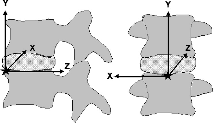
The kinematic behaviour of the specimen was compared for the different test conditions by looking at the intersegmental motion between L3 and L4. Specifically, we calculated NZ and ROM about the primary axis of rotation, to describe the magnitude of the rotation. Furthermore, we calculated the three-dimensional HAM for the L3–L4 segment over the entire motion [8]. The axis position was reported as a penetration point in one plane and its orientation in two planes. A local coordinate system with its origin at the antero-superior point of L4 was defined as follows. Initially, a local xy-plane was established such that it was aligned with the coronal plane of the general specimen coordinate system. This coordinate system was then rotated in the sagittal plane so that the z-axis was in plane with the superior endplate of L4 (based on radiograph). The penetration point of the HAM, therefore, was with the yz-plane for flexion–extension, the xy-plane for lateral bending, and the xz-plane for axial rotation (Fig. 3). The location of the penetration point was normalized based on the height, width, and length of the L4 vertebral body. All kinematic analyses were based on the third loading cycle.
Fig. 3.
Local coordinate system created for L3 and L4 for HAM analysis. Origin is at the antero-superior point of L4
The effect of the spacer length on ROM, NZ, and HAM parameters was determined using repeated measures analysis of variance (ANOVA) at a 95% level of significance. Student–Newman–Keuls (SNK) post-hoc analysis was used to determine the differences between specific cases. Two sets of statistical tests were performed. The first looked at the difference between the intact, injury, and Dynesys standard spacer length (absolute values). The second test focused on differences between the three spacer lengths (normalized to intact).
Results
The ROM with the standard length Dynesys spacer was significantly less than in the intact and injury conditions in all directions of loading with and without a follower preload (P<0.007) (Table 1). The only exception was in axial rotation between the intact and Dynesys conditions with a follower preload (P=0.06). Without a follower preload, rotations ranged from 28 to 33% of intact ROM in flexion, extension, and lateral bending and 72% in axial rotation. With a follower preload, absolute ROM was further reduced and the ratio of ROM for the Dynesys to intact also decreased, except in axial rotation where ROM became a greater percentage of intact ROM.
Table 1.
Absolute average range of motion (ROM) in degrees for an intact specimen, injured specimen, and three different Dynesys spacer lengths (short, standard, and long) in flexion, extension, lateral bending, and axial rotation. (A) Without a compressive follower preload. (B) With a compressive follower preload
| Condition | Flexion | Extension | Lateral bending | Axial rotation |
|---|---|---|---|---|
| A: Without follower load | ||||
| Intact | 3.7±1.5 | 3.3±1.5 | 3.8±1.4 | 2.1±0.9 |
| Injury | 6.1±1.4 | 4.4±1.2 | 5.0±1.8 | 2.8±1.2 |
| Short | 0.5±0.4 | 0.5±0.3 | 0.8±0.5 | 1.3±0.9 |
| Standard | 1.0±0.6 | 1.1±0.7 | 1.0±0.5 | 1.6±1.0 |
| Long | 1.0±0.5 | 1.3±0.9 | 1.2±0.5 | 1.9±0.9 |
| B: With follower load | ||||
| Intact | 4.4±2.0 | 2.4±0.9 | 2.4±1.2 | 1.2±0.5 |
| Injury | 5.8±2.5 | 2.7±1.7 | 1.4±0.9 | 1.3±0.6 |
| Short | 0.4±0.3 | 0.3±0.2 | 0.5±0.3 | 0.9±0.4 |
| Standard | 0.5±0.3 | 0.5±0.3 | 0.5±0.2 | 1.0±0.5 |
| Long | 0.5±0.3 | 0.6±0.2 | 0.6±0.3 | 1.2±0.5 |
Numbers are the average and standard deviation for ten specimens. Lateral bending and axial rotation ROM are reported as an average of one side only
The injury typically increased the NZ, and implantation of the Dynesys generally reduced the NZ to a magnitude below that of the intact spine (except in axial rotation with a follower preload) (Table 2). The differences in NZ between the intact and Dynesys conditions were significant only in lateral bending without (P=0.002) and with (P=0.0002) a follower preload. With the Dynesys, the NZ was significantly less than in the injury condition in all directions of loading without a follower preload (P<0.010) and in flexion–extension with a follower preload (P=0.02).
Table 2.
Absolute average neutral zone (NZ) in degrees for an intact specimen, injured specimen, and three different Dynesys spacer lengths (short, standard, and long) in flexion–extensions, lateral bending, and axial rotation. (A) Without a compressive follower preload. (B) With a compressive preload
| Condition | Flex–Ext | Lateral bending | Axial rotation |
|---|---|---|---|
| A: Without follower load | |||
| Intact | 0.4±0.5 | 0.7±0.4 | 0.3±0.3 |
| Injury | 1.3±1.0 | 1.1±0.7 | 0.5±0.5 |
| Short | 0.1±0.0 | 0.1±0.1 | 0.2±0.2 |
| Standard | 0.2±0.1 | 0.1±0.1 | 0.3±0.3 |
| Long | 0.2±0.2 | 0.2±0.1 | 0.3±0.2 |
| B: With follower load | |||
| Intact | 0.6±0.5 | 1.1±0.6 | 0.1±0.1 |
| Injury | 0.8±0.8 | 0.5±0.3 | 0.2±0.2 |
| Short | 0.1±0.0 | 0.1±0.1 | 0.2±0.1 |
| Standard | 0.1±0.1 | 0.1±0.1 | 0.2±0.2 |
| Long | 0.1±0.0 | 0.2±0.1 | 0.2±0.2 |
Numbers are the average and standard deviation for the ten specimens
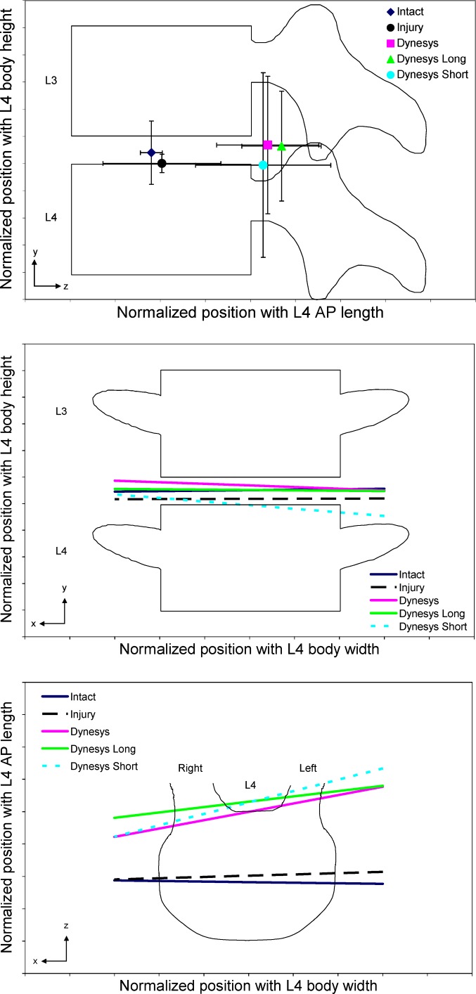
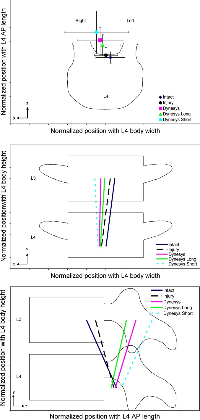
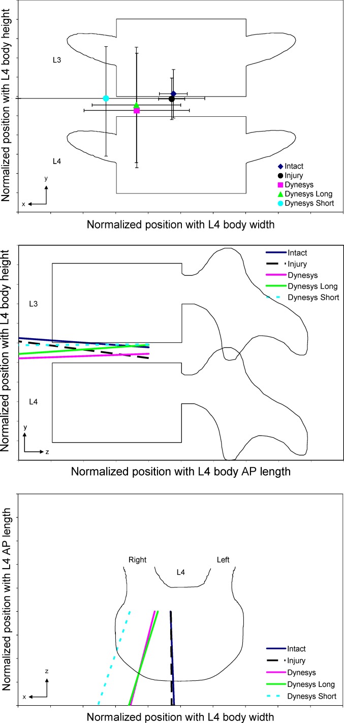
Injury did not cause a significant difference in the position or orientation of the HAM compared to the intact condition (P>0.05), except in the superior–inferior direction in lateral bending with a follower preload (P=0.03). Implantation of the Dynesys did significantly affect the HAM as compared to the intact specimen (Figs. 4, 5, 6). Without and with a follower preload, there was a posterior shift in the location of the HAM in flexion–extension (P<0.0008) and axial rotation (P<0.04) with the implant. Typically, the HAM moved laterally to the right in axial rotation (P>0.07) and lateral bending (P=0.03 without a follower preload and P=0.13 with a follower preload) with the Dynesys. Orientation of the HAM in flexion–extension without a compressive follower preload significantly rotated counter–clockwise in the xz (L4 superior endplate) plane (P=0.002). In axial rotation without a follower preload, the HAM rotated clockwise in the yz (mid-sagittal) plane (P=0.003). There were no significant differences in the orientation of the HAM in lateral bending.
Fig. 4.
Helical axis of motion (HAM) in flexion–extension with no follower load. The results presented are the average for ten specimens and have been normalized by the height, width, and length of the L4 vertebral body
Fig. 5.
Helical axis of motion (HAM) in axial rotation with no follower load. The results presented are the average for ten specimens and have been normalized by the height, width, and length of the L4 vertebral body
Fig. 6.
Helical axis of motion (HAM) in lateral bending with no follower load. The results presented are the average for ten specimens and have been normalized by the height, width, and length of the L4 vertebral body
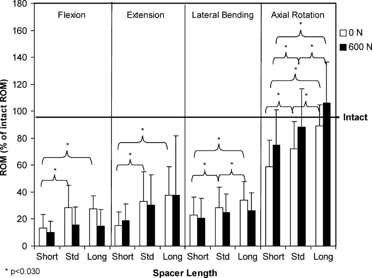
In all loading directions, there was generally an increase in ROM with the long spacer and a reduction in ROM with the short spacer, as compared to the kinematics of the standard length spacer. Without a compressive follower preload, the spacer length did create a difference in ROM with P<0.006 (Table 1, Fig. 7). Post-hoc analysis revealed that the differences were significant between all the three spacer lengths (P<0.015), except between the long and standard spacer in flexion and extension (P>0.474). While the same trend was seen with a follower preload, the changes in ROM were only significant in axial rotation and were between all three spacer lengths (P<0.030).
Fig. 7.
Average rotations with the three different Dynesys spacers (short, standard, and long), normalized to intact ROM. All the three directions of loading, with and without a follower preload
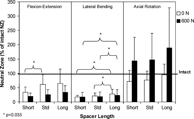
The NZ was typically greatest with the long spacer and least with the short spacer (Table 2, Fig. 8). However, between the various spacer lengths, the difference in NZ was only significant in flexion–extension (without a follower preload) between the standard and short spacers (P=0.033) and in lateral bending (with and without a follower preload) between the long and standard spacers (P<0.032) and between the short and long spacers (P<0.018).
Fig. 8.
Average neutral zone for the three different Dynesys spacers (short, standard, and long), normalized to intact neutral zone. All three directions of loading, with and without a follower preload
There were no significant differences (P>0.05) in orientation or location of the HAM between the three spacer lengths, except in axial rotation with a follower preload where the HAM with the short spacer was significantly more posterior than with the long spacer (P=0.033) and significantly rotated clockwise in the yz (mid-sagittal) plane (P=0.033) (Figs. 4, 5, 6). The other exception was in flexion–extension without a follower preload, where the short spacer resulted in a significant difference in orientation compared to the long spacer in the xz (endplate) plane (P=0.035).
Discussion
A comprehensive biomechanical evaluation is necessary for non-fusion spinal stabilization techniques. The goal of dynamic spinal stabilization is to restore normal segmental kinematics to the spine. This includes not only the ROM, but also the motion pattern as represented by the location and orientation of the HAM. The motion pattern, less investigated in previous studies, has an effect on the loading profile within the facet joints, intervertebral disc, and posterior ligaments, as well as on the adjacent segments. The purpose of this in vitro study was to perform a comprehensive kinematic analysis to determine if the length of the Dynesys spacer affects kinematic behaviour. Ten lumbar specimens were subjected to flexibility testing in flexion–extension, lateral bending, and axial rotation, with and without a compressive follower preload. Kinematic evaluation included ROM, NZ, and HAM.
The results of this study show that in all the three loading directions there was an increase in ROM with the long spacer and a reduction in ROM with the short spacer compared to the standard spacer. The differences in ROM observed with different spacer lengths were significant in all the directions of loading without a follower preload (except between the standard and long spacers in flexion and extension), but the most significant change was seen in axial rotation. Compared to intact and injured specimens, all the three lengths of Dynesys spacers resulted in a significantly lower ROM with the least significant reduction observed in axial rotation. There were not many significant changes in NZ between the different spacer lengths. The Dynesys tended to reduce the larger NZ of the injured specimen to a magnitude that was below that of the intact specimen. Changes in NZ were significant between the Dynesys and injury condition, but typically not significant between the Dynesys and the intact specimen (except in lateral bending). With a follower preload, the differences in NZ were less significant and only present in lateral bending. Only in axial rotation with a follower preload were there significant differences in location of the HAM between spacer lengths. Generally, the shorter the spacer, the more posteriorly the HAM was located. There were significant differences in the orientation of the HAM in flexion–extension (without a follower preload) and axial rotation (with a follower preload) between the long and short spacers. The most significant changes in the HAM took place with the implantation of the Dynesys system as compared to the intact specimen. The HAM moved posteriorly when the Dynesys was implanted. In addition, there was a shift in the orientation of the axis in flexion–extension and axial rotation.
The standard deviation of the HAM with the implanted Dynesys was relatively large. The position and direction errors are inversely proportional to the rotation magnitude [22]. Thus, the accuracy of the HAM is lower under small rotations. With the Dynesys implanted, the motion is small; hence, in some cases the calculated HAM was ill-defined and excluded from the analysis. No more than two specimens were excluded concurrently. In this study, the pedicle screws were cemented in place using PMMA to eliminate the loosening at the bone–screw interface since this was not the focus of this study. This is typically not done as a part of the surgical procedure, so it may not be clinically relevant. However, the stiffness of the pedicle bone–screw interface may potentially influence the function of the implant with respect to the kinematic behaviour of the segment. Due to the decreased stiffness of the spacer used in this study compared to a spacer used in vivo, the applied tensile preload leads to a lesser screw distance compared to the intra-operative situation. Therefore, the segment experiences more compression after implantation leading to a decreased disc height and a smaller gap in the facet joints. In the present study, we suspect that the long spacer (+2 mm) is representative of the in vivo situation.
The age of the specimens tested in this study was fairly old; hence, there may have been degenerative changes present. This was not anticipated to have a significant effect on the results. Even though patients receiving this implant are often from a younger population, the device is implanted to try and correct a problem, often one resulting from disc degeneration. In addition, it has been previously shown that disc degeneration has a minimal effect on the ROM [12] and may even result in a decrease in ROM in the latter stages [5].
The magnitude of the applied rate of rotation in this study was only approximate. After the study was concluded, we discovered that there was some undesirable slippage along the joints of the spine machine arm, which led to a rotation rate that was proportional to the stiffness of the specimen. The variability in rotation rate between specimens was less than 0.4°/s in flexion–extension. Slight reductions in the rotation rate with the Dynesys implants were due to a small increase in stiffness once the device was implanted. However, if this did affect our results, the tendency would be towards more conservative measurements. An increase in stiffness would cause a decrease in the applied rotation rate, and due to the viscoelastic properties of the spine, this would lead to an increase in ROM. Therefore, in this study, the ROM resulting from testing with the implanted Dynesys may in fact be even smaller than what was measured.
The strength of this study was that it incorporated HAM into the investigation of the kinematic behaviour. This created a very complete analysis of the kinematics with the implanted Dynesys system. All the testing was done with and without a compressive follower preload, which shows the effect that the application of the follower preload has on the kinematic behaviour. Also, a follower preload has been shown to be an effective means of simulating physiological conditions in in vitro studies [16].
Constraint to segmental motion is created not only by the Dynesys configuration, such as a pre-tensioned cord, but also by the compression of the segment (intervertebral disc and facet joints) that is produced with the device. Segmental compression, especially at the posterior elements, is largely dependent on the spacer length, which affects intersegmental ROM, most notably in axial rotation. In the present study, a 4 mm change in spacer length led to an average intersegmental motion change of 30% in axial rotation, 23% in extension, 14% in flexion, and 11% in lateral bending. With the long spacer, there was an increase in ROM, a smaller posterior shift in the position of the HAM in axial rotation, and a typically smaller change in the orientation of the HAM as compared to the short spacer. Concurrent work by our group found that the average initial contact load in the facet joints created by the implantation of the device changed from 15 N with the long spacer to 42 N with the short spacer [13]. These initial static facet loads show that there was less contact between the facets when the long spacer was implanted. The long spacer reduced segmental compression and therefore increased ROM. Lund et al. [10] observed similar results when looking at the effects of variations in the compression of posterior instrumentation on motion. In that study, distraction of the posterior elements resulted in a greater motion along the anterior column when loaded in axial compression. Although Lund et al. examined the effects only in axial loading, their results are consistent with the findings of our study in determining that the stiffness of the segment was affected by the length of the spacer, which resulted in kinematic changes.
As is evident by the lateral shift in HAM in lateral bending and the non-significant shift in axial rotation with the implantation of the Dynesys, the bilateral nature of the system introduced an asymmetric stiffness to the segment. The order of implantation was performed randomly between the right and left sides and thus the asymmetry appeared independent of which side was installed first. Reasons for this observation could include the small variation in the pre-tension that was applied to the cord, differences that may have occurred in sizing the standard spacer length, and the operative technique. The asymmetrical stiffness may have important implications clinically.
Even though ROM was substantially reduced with the implanted Dynesys, the long spacer produced kinematic behaviour that was more similar to that of an intact spine compared to the other spacer lengths tested. As mentioned earlier, we suspect that the long spacer may better represent the intra-operative situation due to the softer material and thereby higher compression during implantation in the present study. However, a balance between desirable kinematics and neutral position of the spine must be found. By increasing the length of the spacer too much, the spine may potentially become kyphotic, which may lead to adverse changes in loading patterns and additional clinical problems not predictable with in vitro testing.
Intact ROM at the L3–L4 level determined in this study was comparable to the range of values reported in the literature in all directions of loading [5, 12, 15, 20, 23] (Table 3). Intersegmental ROM observed at the implanted level with the Dynesys in this study was similar to that obtained by Schmoelz et al. [20] in all the loading directions except extension (Table 4). The ROM with the Dynesys was only slightly greater in the Schmoelz study, which may be explained by their larger applied moment (±10 Nm). In extension, however, the difference in ROM between the two studies was more considerable. Schmoelz et al. observed a ROM with the Dynesys that was in the range of the intact specimen, whereas we saw a decrease in the motion by an average of 67%. The ROM reported by Freudiger et al. [3] in flexion–extension was much greater than the values observed in our study. This might be due to a larger applied moment and a different mechanism for the application of the load. However, in that study, the model did not include destabilization, so motions may have been even greater had an injury been created. Freudiger et al. did notice a significant decrease in ROM of nearly 50% with the Dynesys compared to an intact specimen, which is consistent with the results of this study.
Table 3.
Range of motion (ROM) comparison for intact specimen
| Flexion | Extension | Lateral bending | Axial rotation | |
|---|---|---|---|---|
| Panjabi et al. [15] 7.5 Nm | 6.5 | 2.0 | 5.0/4.5 | 1.8/2.0 |
| Fujiwara et al. [5] 6.6 Nm (Male) | 3.0 | 2.4 | 7.3 | 2.3 |
| Mimura et al. [12] 10 Nm | 12.8 | → | 11.0 (2.5) | 2.5 (2.0) |
| Schmoelz et al. [20] 10 Nm | 4.5 | 4.0 | 4.0/5.0 | 1.0/1.0 |
| Yamamoto et al. [23] 10 Nm | 7.5 (0.8) | 3.7 (0.3) | 5.8 (0.5)/5.7 (0.3) | 2.7 (0.4)/2.5 (0.4) |
| Freudiger et al. [3] 18.3 Nm | 9.6 (1.7) | 2.1 (1.0) | ||
| Our study 7.5 Nm | 3.7 (1.5) | 3.3 (1.5) | 3.5 (1.4)/4.1 (1.5) | 2.2 (0.9)/1.2 (0.6) |
Values represent ROM in degrees for an intact specimen in vitro. The applied moment for each study is also provided. In lateral bending and axial rotation, the motion is shown as right/left or total. Numbers in parentheses are the standard deviations, where available
Table 4.
Range of motion (ROM) comparison with Dynesys system
| Flexion | Extension | Lateral bending | Axial rotation | |
|---|---|---|---|---|
| Freudiger et al. [3] 18.3 Nm | 4.3 | 1.1 | ||
| Schmoelz et al. [20] 10 Nm | 1.0 | 4.0 | 1.8/1.1 | 2.0/1.7 |
| Our study 7.5 Nm | 1.0 | 1.1 | 0.9/1.1 | 1.7/1.5 |
Values represent ROM in degrees for a specimen with the implanted Dynesys system (standard length). The applied moment for each study is also provided. In lateral bending and axial rotation, the motion is shown as right/left or total
With a follower preload, generally, the same trends were seen in ROM, NZ, and HAM as those seen without a follower preload, but typically the differences between the test conditions were smaller. The ROM decreased in all the three loading directions with a follower load and since the motion with the Dynesys was already small, differences between the spacers became less pronounced. This is consistent with the previous studies [6, 17, 18]. NZ decreased in flexion–extension and axial rotation with the application of a follower load, but increased in lateral bending, which could be related to the lateral fixation of the follower preload. In flexion–extension, compared to testing without a follower preload, the follower load tended to shift the HAM with the Dynesys implants anteriorly towards the location of the intact HAM.
In summary, the magnitude of ROM in all the loading directions with the Dynesys was significantly lower that that of the intact and injured specimens. The differences observed were least significant in axial rotation. Injury typically increased the NZ, but implantation of the Dynesys restored the NZ to a magnitude less than that of the intact spine. The HAM was located significantly more posteriorly in flexion–extension and axial rotation with the Dynesys than in the intact condition. The spacer length of the Dynesys did affect the kinematic behaviour. ROM was affected most significantly, followed by HAM, and finally NZ in which no significant differences were observed between the three spacer lengths. The long spacer resulted in a ROM and motion pattern, as represented by the location and orientation of the HAM, that was closer to that seen in an intact specimen. Observations with the use of even longer spacers indicated that there may exist a maximum spacer length that once exceeded would place the spine in a significantly altered neutral position such that the spine becomes kyphotic. Inclusion of both the magnitude and pattern of motion, as in this study, provides valuable information necessary to perform a comprehensive biomechanical evaluation of non-fusion systems for the spine.
Acknowledgements
The authors wish to gratefully acknowledge the funding from the Synos Foundation, Switzerland, Zimmer GmbH, and Natural Sciences and Engineering Research Council of Canada (NSERC). The experiments in this study complied with the current testing laws in Canada and were approved by the University of British Columbia Clinical Research Ethics Board.
References
- 1.Andersson GB. Epidemiological features of chronic low-back pain. Lancet. 1999;354:581–585. doi: 10.1016/S0140-6736(99)01312-4. [DOI] [PubMed] [Google Scholar]
- 2.Eck JC, Humphreys SC, Hodges SD. Adjacent-segment degeneration after lumbar fusion: a review of clinical, biomechanical, and radiologic studies. Am J Orthop. 1999;28:336–340. [PubMed] [Google Scholar]
- 3.Freudiger S, Dubois G, Lorrain M. Dynamic neutralisation of the lumbar spine confirmed on a new lumbar spine simulator in vitro. Arch Orthop Trauma Surg. 1999;119:127–132. doi: 10.1007/s004020050375. [DOI] [PubMed] [Google Scholar]
- 4.Fritzell Spine. 2001;26:2521. doi: 10.1097/00007632-200112010-00002. [DOI] [PubMed] [Google Scholar]
- 5.Fujiwara A, Lim TH, An HS, et al. The effect of disc degeneration and facet joint osteoarthritis on the segmental flexibility of the lumbar spine. Spine. 2000;25:3036–3044. doi: 10.1097/00007632-200012010-00011. [DOI] [PubMed] [Google Scholar]
- 6.Gardner-Morse MG, Stokes IA. Physiological axial compressive preloads increase motion segment stiffness, linearity and hysteresis in all six degrees of freedom for small displacements about the neutral posture. J Orthop Res. 2003;21:547–552. doi: 10.1016/S0736-0266(02)00199-7. [DOI] [PubMed] [Google Scholar]
- 7.Goertzen DJ, Lane C, Oxland TR. Neutral zone and range of motion in the spine are greater with stepwise loading than with a continuous loading protocol. An in vitro porcine investigation. J Biomech. 2004;37:257–261. doi: 10.1016/S0021-9290(03)00307-5. [DOI] [PubMed] [Google Scholar]
- 8.Kinzel GL, Hall AS, Jr, Hillberry BM. Measurement of the total motion between two body segments. I. Analytical development. J Biomech. 1972;5:93–105. doi: 10.1016/0021-9290(72)90022-X. [DOI] [PubMed] [Google Scholar]
- 9.Lee CK. Accelerated degeneration of the segment adjacent to a lumbar fusion. Spine. 1988;13:375–377. doi: 10.1097/00007632-198803000-00029. [DOI] [PubMed] [Google Scholar]
- 10.Lund T, Rathonyi G, Schlenzka D, et al. The external spinal fixator does not reduce anterior column motion under axial compressive loads. A mechanical in vitro study. Acta Orthop Scand. 1999;70:37–41. doi: 10.3109/17453679909000955. [DOI] [PubMed] [Google Scholar]
- 11.McKinnon ME, Vickers MR, Ruddock VM, et al. Community studies of the health service implications of low back pain. Spine. 1997;22:2161–2166. doi: 10.1097/00007632-199709150-00014. [DOI] [PubMed] [Google Scholar]
- 12.Mimura M, Panjabi MM, Oxland TR, et al. Disc degeneration affects the multidirectional flexibility of the lumbar spine. Spine. 1994;19:1371–1380. doi: 10.1097/00007632-199406000-00011. [DOI] [PubMed] [Google Scholar]
- 13.Niosi CA, Zhu QA, Wilson DC, et al (2004) Does spacer length of dynamic posterior stablization system have an effect on range of motion? ISSLS 31st Annual Meeting (Poster) Porto, Portugal
- 14.Panjabi MM, Krag MH, Goel VK. A technique for measurement and description of three-dimensional six degree-of-freedom motion of a body joint with an application to the human spine. J Biomech. 1981;14:447–460. doi: 10.1016/0021-9290(81)90095-6. [DOI] [PubMed] [Google Scholar]
- 15.Panjabi MM, Oxland TR, Yamamoto I, et al. Mechanical behavior of the human lumbar and lumbosacral spine as shown by three-dimensional load–displacement curves. J Bone Joint Surg Am. 1994;76:413–424. doi: 10.2106/00004623-199403000-00012. [DOI] [PubMed] [Google Scholar]
- 16.Patwardhan AG, Havey RM, Meade KP, et al. A follower load increases the load-carrying capacity of the lumbar spine in compression. Spine. 1999;24:1003–1009. doi: 10.1097/00007632-199905150-00014. [DOI] [PubMed] [Google Scholar]
- 17.Patwardhan AG, Havey RM, Carandang G, et al. Effect of compressive follower preload on the flexion–extension response of the human lumbar spine. J Orthop Res. 2003;21:540–546. doi: 10.1016/S0736-0266(02)00202-4. [DOI] [PubMed] [Google Scholar]
- 18.Rohlmann A, Neller S, Claes L, et al. Influence of a follower load on intradiscal pressure and intersegmental rotation of the lumbar spine. Spine. 2001;26:E557–E561. doi: 10.1097/00007632-200112150-00014. [DOI] [PubMed] [Google Scholar]
- 19.Schlegel JD, Smith JA, Schleusener RL. Lumbar motion segment pathology adjacent to thoracolumbar, lumbar, and lumbosacral fusions. Spine. 1996;21:970–981. doi: 10.1097/00007632-199604150-00013. [DOI] [PubMed] [Google Scholar]
- 20.Schmoelz W, Huber JF, Nydegger T, et al. Dynamic stabilization of the lumbar spine and its effects on adjacent segments: an in vitro experiment. J Spinal Disord Tech. 2003;16:418–23. doi: 10.1097/00024720-200308000-00015. [DOI] [PubMed] [Google Scholar]
- 21.Stoll TM, Dubois G, Schwarzenbach O. The dynamic neutralization system for the spine: a multi-center study of a novel non-fusion system. Eur Spine J. 2002;11(Suppl 2):S170–S178. doi: 10.1007/s00586-002-0438-2. [DOI] [PMC free article] [PubMed] [Google Scholar]
- 22.Woltring HJ, Huiskes R, Lange A, et al. Finite centroid and helical axis estimation from noisy landmark measurements in the study of human joint kinematics. J Biomech. 1985;18:379–389. doi: 10.1016/0021-9290(85)90293-3. [DOI] [PubMed] [Google Scholar]
- 23.Yamamoto I, Panjabi MM, Crisco T, et al. Three-dimensional movements of the whole lumbar spine and lumbosacral joint. Spine. 1989;14:1256–1260. doi: 10.1097/00007632-198911000-00020. [DOI] [PubMed] [Google Scholar]


