Abstract
The purpose of this study was to (1) develop a three-dimensional, nonlinear pediatric lumbar spine finite element model (FEM), and (2) identify the mechanical reasons for the posterior apophyseal bony ring fracture in the pediatric patients. The pediatric spine FE model was created from an experimentally validated three-dimensional adult lumbar spine FEM. The size of the FEM was reduced to 96% taking into account of the ratio of the sitting height of an average 14-years-old children to that of an adult. The pediatric spine was created with anatomically specific features like the growth plate and the apophyseal bony ring. For the stress analyses, a 10-N m moment was applied in all the six directions of motion for the lumbar spine. A preload of 351 N was applied which corresponds to the mean body weight of the 14-years-old group. The stresses at the apophyseal bony ring, growth plate and endplate were calculated. The results indicate that the structures surrounding the growth plate including apophyseal bony ring and osseous endplate were highly stressed, as compared to other structures. Furthermore, posterior structures in extension were in compression whereas in flexion they were in tension, with magnitude of stresses higher in extension than in flexion. Over time, the higher compression stresses along with tension stresses in flexion may contribute to the apophyseal ring fracture (fatigue phenomena).
Keywords: Pediatric spine, Apophyseal ring fracture, Biomechanics, Finite element model, Growth plate
Introduction
Unlike the adult spines, the pediatric spine has unique anatomical features like the growth plate and apophyseal ring. Due to the presence of these features, the biomechanical behavior of pediatric spine is quite different from the adult spine. In the pediatric spine the growth plate is reported to be the weakest link and a cause of isthmic spondylolisthesis [6, 9, 10]. The apophyseal ring fracture is also a frequent disorder in immature spines [1, 5, 14]. These disorders are the major causes of low back pain in children and adolescents and are extremely rare in the adult mature spine, in part due to the absence of the growth plate or apophyseal ring. Since these disorders are stress related, a biomechanical approach may be optimum to understand the etiology.
Procuring fresh pediatric spine specimens is very difficult and also impractical. Due to this, we previously used immature animal spines such as calf spines [6, 9, 10] and baboon spines [8] to investigate the biomechanics of pediatric spondylolysis. One may develop mathematical models to address the issue. Such an investigation was undertaken using the finite element model (FEM) of a baboon spinal motion segment [8]. However, one needs to undertake studies on pediatric population and the only practical approach would be the analytical approach. It is not practical to develop even the FEM of a pediatric spine since this will involve acquiring thin slices (say at 1-mm interval) of CT scans. For these reasons, there are no pediatric finite element lumbar spine models reported in the literature, although a large number of similar models for the adult spinal segments are available [2–4, 7, 8, 12].
The purpose of this study was to (1) develop a three-dimensional, nonlinear pediatric lumbar spine FEM, and (2) understand the biomechanical causes for the posterior apophyseal bony ring fracture in the pediatric patients. In the part II of this study, the causes for spondylolytic slippage at the growth plate in pediatric spine are discussed, based on the stress analyses predictions from the pediatric FE model.
Methods
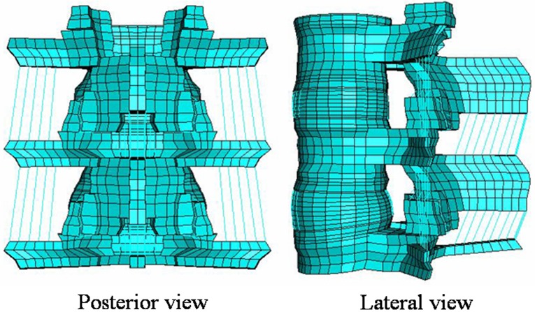
An adult three-dimensional L3–L5 spinal segment FEM presently available to the authors was used for the present study (Fig. 1). The adult model is experimentally validated, and has been widely used to address clinically relevant issues [2–4, 7, 8, 12]. Since it is very difficult to get precise CT scans from the pediatric patients, we modified the adult model to correspond to the pediatric spine.
Fig. 1.
Experimentally validated adult L3–L5 ligamentous finite element model (FEM). The model was modified to the pediatric model
The pediatric immature spine can be in two stages depending on if the apophyseal ring is cartilaginous or ossified [11]. In this study, our focus is on the etiology of the apophyseal bony ring fracture; hence we considered the apophyseal ring to be ossified. The apophyseal ring ossification occurs around the age of 10–15. Taking the ratio of mean sitting height of adults and children of 14 years old, we reduced the size of the adult spine model to 96% of its original size [15] for this study. The mesh was symmetric across the mid-sagittal plane.
Intact pediatric spine model
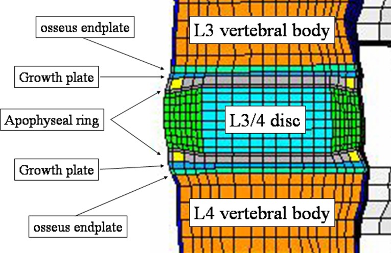
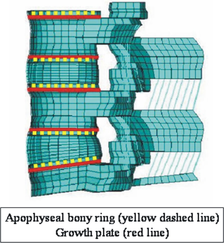
The present intact pediatric spine model included 13,416 elements (Table 1). The mesh was symmetric across the mid-sagittal plane. The vertebral bodies were defined as cancellous bone cores surrounded by 0.5 mm thick cortical shells. The pediatric spine has characteristic growth plates and apophyseal bony ring. With reference to the anatomy of the pediatric spine specified by Arlet and Fassier [1], we changed the adult spine and added growth plates and apophyseal rings. Figure 2 shows the location of the growth plate and apophyseal ring as seen in the sagittal plane. In Fig. 3, apophyseal bony rings (yellow lines) and growth plate (red lines). The growth plate was modeled as a layer of cartilage tissue between the vertebral body and apophyseal bony rings with cancellous bone. The sagittal section of the apophyseal bony ring is highlighted in yellow color. The cartilaginous endplate was simulated by filling cartilage tissue inside of the apophyseal bony ring.
Table 1.
Details of the pediatric spine finite element model
| Element set | Number of elements | ABAQUS element (library type) | Young’s modulus (MPA) | Poisson’s ratio | |
|---|---|---|---|---|---|
| Bony regions | Cortical bone | 512 | C3D8 | 12,000 | 0.30 |
| Cancellous bone | 3,328 | C3D8 | 100 | 0.20 | |
| Posterior bone | 1,256 | C3D8 | 3,500 | 0.25 | |
| Endplate | 1,200 | C3D8 | 3,000 | 0.25 | |
| Apophyseal ring | 160 | C3D8 | 100 | 0.20 | |
| Growth plate | 1,200 | C3D8 | 10 | 0.40 | |
| Intervertebral disc | Annulus fibrosus | 3,584 | C3D8 | 4.2 | 0.45 |
| Nucleus pulposus | 1,792 | C3D8 | 1.0 | 0.4999 | |
| Ligaments | Anterior longitudinal | 160 | T3D2 | 15.6–20.0 | 0.30 |
| Posterior longitudinal | 96 | T3D2 | 10.0–20.0 | 0.30 | |
| Transverse | 20 | T3D2 | 12.0–59.0 | 0.30 | |
| Ligamentum flavum | 16 | T3D2 | 13.0–19.5 | 0.30 | |
| Interspinous | 28 | T3D2 | 9.8–12.0 | 0.30 | |
| Supraspinous | 8 | T3D2 | 8.8–15.0 | 0.30 | |
| Capsular | 56 | T3D2 | 8.48–32.9 | 0.30 |
Fig. 2.
Sagittal section of the pediatric FEM at L3–L4. Note the layers of growth plate and apophyseal bony ring, which are the specific structures in the pediatric spine. In this model, apophyseal ring was simulated as a bony ring
Fig. 3.
Location of apophyseal bony ring (yellow lines) and growth plate (red lines)
The intervertebral disk annulus was modeled as a composite of a solid matrix with embedded fibers (via the REBAR parameter) in concentric rings around a pseudo-fluid nucleus. Seven concentric rings of ground substance each containing two evenly spaced layers of fibers (plus one ground substance ring with one layer of fibers) oriented at ±30° to the horizontal were simulated. Fiber thickness and stiffness increased in the radial direction. The posterior bone regions were assigned a single set of material properties. The facet joints were simulated with three-dimensional gap contact elements (GAPUNI).
All seven major spinal ligaments were represented and assigned nonlinear material properties. Naturally, changing ligament stiffness (initially low stiffness at low strains followed by increasing stiffness at higher strains) was simulated through the “hypoelastic” material designation, which allowed the definition of the axial stiffness as a function of axial strain. Three-dimensional two-node truss elements (T3D2) were used to construct the ligaments.
The material properties of the cortical bone of the vertebral body, cancellous bone, posterior bone, nucleus pulposus, annulus fibrosus, and ligaments, were same as that of the adult model [2–4, 7, 8, 12]. The material properties for the growth plate and apophyseal bony ring were adapted from the literature [8] and are shown in Table 1.
Load application and analyses
Axial compressive preload of 400 N was applied. This value simulates the load at the L3–L4 level of an average person while standing [2–4, 7, 8, 12]. The axial compression preload was reduced to 351 N in the pediatric model, (87.9% of the adult 400 N) [15]. A pure moment of 10 N m was applied along with the preload to simulate segment behavior in flexion, extension, lateral bending, and axial rotation. von Mises stresses were computed at various sites within the model. The stresses around the posterior apophyseal ring at L4–L5 segment were investigated because of high incidence of posterior apophyseal ring fracture at this level. The normal stresses, in S33 (vertical) direction were also computed. Commercially available FEM software ABAQUS CAE, version 6.0 was used for this analysis.
Results
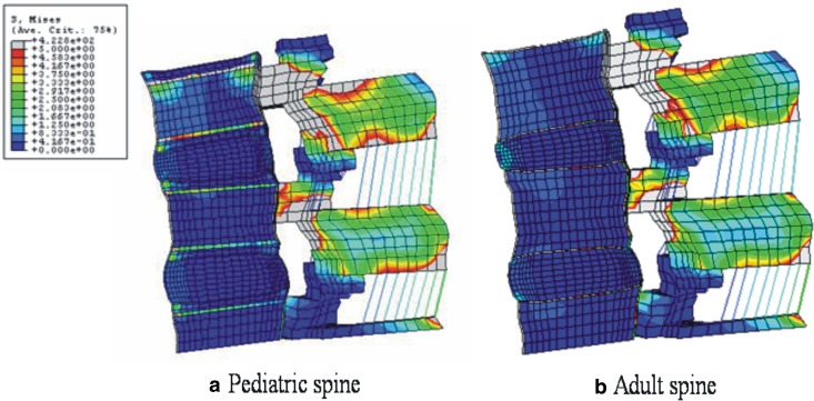
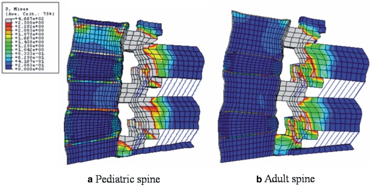
In flexion with preload, high von Mises stresses were observed at the anterior annulus fibrosus, apophyseal ring, and osseous endplates. von Mises stresses in flexion in the mid-sagittal plane of the pediatric model are shown in Fig. 4a. Unlike to the adult model (Fig. 4b), the apophyseal ring experienced the most stress. Figure 5a, b shows von Mises stresses in extension in the sagittal section of the pediatric and adult models, respectively. The posterior region in the pediatric model had higher stresses, as compared to the adult model. The most marked differences between pediatric and adult models were found in the apophyseal ring.
Fig. 4.
a Stress distributions in 10 N m flexion and a preload in pediatric, and b adult spine models. In both models, higher stresses were observed around pedicle and facet joints. In the anterior structures, the stress concentration at osseous endplate and apophyseal bony ring was observed in the pediatric model, whereas, in the adult model endplate showed stress concentration
Fig. 5.
a Stress distributions in extension at 10 N m with precompression loading in pediatric and b adult spine models: In both models, higher stresses are observed around pedicle and facet joints during the extension motion. In the anterior structures, the stress concentration at osseous endplate and apophyseal bony ring is observed in the pediatric model, whereas, in the adult model endplate shows stress concentration
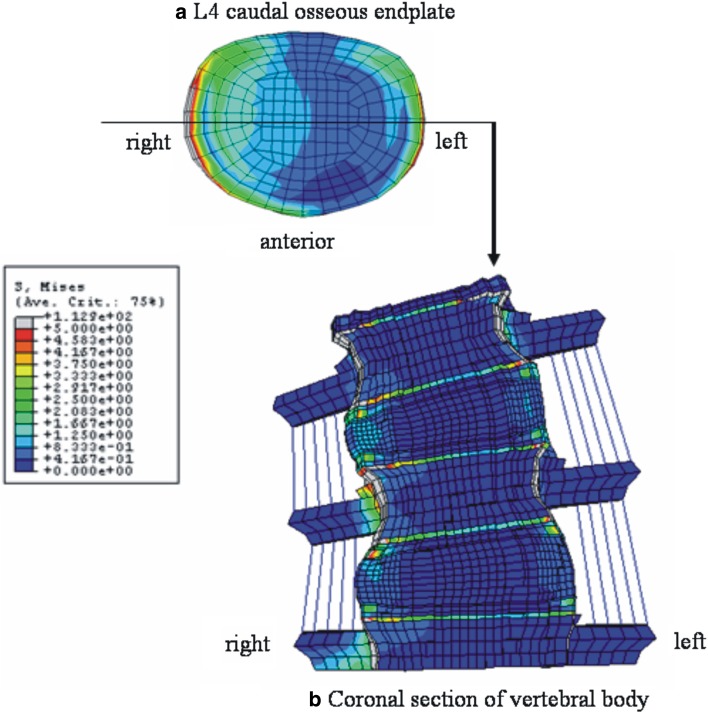
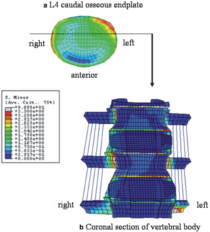
Figure 6 shows the stress distribution in right lateral bending. Both the right and left lateral corners were highly stressed (Fig. 6a). Figure 6b is the coronal section of the model through the middle of vertebral body, which was cut along the line as shown in Fig. 6a. High stresses were observed in the apophyseal bony ring. In axial rotation, right anterior corner and left lateral corner were highly stressed (Fig. 7a). Figure 7b indicates the coronal section through the anterior one-third of the vertebral body, location shown in Fig. 7a. The apophyseal bony rings experienced the highest stresses.
Fig. 6.
Stress distributions in right lateral bending at 10 N m with precompression loading in pediatric models. a Top view of the L4 caudal osseous endplate, b anterior view of the coronal section of the model through the middle of vertebral body as indicated in a. In a, both right and left lateral corner are shown to be highly stressed due to compression and traction force, respectively. The stress distribution pattern in b indicates the high loading at the osseous endplate and apophyseal bony ring
Fig. 7.
Stress distributions in right axial rotation at 10 N m with precompression loading in pediatric models. a Top view of the L4 caudal osseous endplate, b anterior view of the coronal section of the model through the anterior one-third of vertebral body as indicated in a. In a, left posterior–lateral corner is shown to be highly stressed. The stress distribution pattern in b indicates the high loading at the osseous endplate and apophyseal bony ring
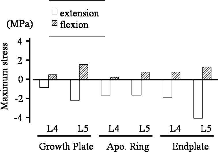
In Fig. 8, normal stresses (S33) at the posterior structures around disk space in the axial direction are depicted (tension positive and compression negative). Posterior structures were loaded in compression in extension whereas in flexion they were in tension. The absolute values of stresses were always higher in extension than in flexion.
Fig. 8.
Axial stresses at the posterior structures around the apophyseal ring (positive value traction, negative value compression). Posterior structures were loaded in compression in extension whereas in flexion they were in tension. The absolute values of stresses were always higher in extension than in flexion. (Apo Ring apophyseal bony ring)
Discussion
The biomechanical study of pediatric lumbar spines has been limited due to a lack of pediatric cadavers for experimental studies. A mathematical model can be used instead of experimental studies for this reason. For developing a mathematical model, geometry is very important. Getting the geometry of pediatric spine is difficult by CT since it involves radiation exposure to the child. Also the apophyseal ring and growth plates are not very evident on CT images. In this study, an adult lumbar spine FEM was modified to create a pediatric lumbar spine FEM with growth plates and apophyseal bony rings.
For the reason stated above, it was not practical to validate the pediatric model using a cadaveric experimental study, and thus is a potential limitation of the current study. Although our model has pediatric specific anatomical layers such as growth plate and apophyseal ring, we did not modify the other structures. For example, facet angle and disk height body ratio in the pediatric spine may differ from the adult spine. To create the exact pediatric FE model, we need precise CT images as described above. We also need to simulate variations in the material properties that may be there in pediatric versus adult population. However, such data are not available in the literature. However, we have an indirect validation of our pediatric model that provides support towards the correctness of stress predictions and locations of the stress concentrations. The computed center of rotation path was in good agreement with the radiographic study of IAR conducted by Sakamaki et al. [13], Fig. 5, part II of the study. The actual magnitudes are likely to be fine tuned when the model is based on actual data, material properties of various structures and is validated with experimental studies.
We previously demonstrated that growth plate was mechanically, the weakest link in AP shear [6, 10], and axial pull [9]. In this study the growth plate, which is mechanically very weak, seems to experience higher stresses. Thus, our previous studies and the present results indicate that among the pediatric population with immature lumbar spines, growth plate region is likely to contribute the most to stress-related lumbar disorders.
There are a couple of lumbar disorders, which are only seen in the pediatric spine and never occurred in the adult spines; i.e., apophyseal ring fracture [1, 5, 14] and lumbar spondylolisthesis at growth plate [6, 9, 10]. The present results clearly demonstrate that stress distribution in the pediatric spine is different from the adult spines, especially at the anterior compartment. One can assume that these anatomical and biomechanical special features in the pediatric spine can cause these pediatric spine related disorders. In part I of this study, we will discuss on the pathomechanism of the apophyseal ring fracture, and in part II, on the pediatric spondylolisthesis.
As shown in our results, the apophyseal bony ring is always highly stressed compared to the surrounding cartilaginous tissue, including growth plate and cartilaginous endplate. This high-stress concentration at the apophyseal bony ring is due to the differences in material properties of tissue in that region. When compared to the surrounding cartilaginous tissue, the apophyseal bony ring is a stiffer material, like cancellous bone. The stiffer material will exhibit higher stresses. This increase in stresses, we believe, is the primary reason for the fractures.
The apophyseal ring fracture has been considered to be the traction force-induced avulsion fracture during flexion [14]. In this study, the tensile stresses during flexion around the posterior apophyseal bony ring were lesser than compression stresses (Fig. 8). Based on the stress results, we suggest that the posterior apophyseal ring is highly stressed during extension and hence weakened mechanically. In flexion, the weakened posterior corner is avulsed with traction stress. We may further extrapolate that, the hyperextension loading during sports activities in children and adolescents may not be favorable, because it may weaken the posterior growth plate, leading to apophyseal bony ring fracture. To understand the etiology of the apophyseal bony ring fracture, biomechanical fatigue test using fresh pediatric cadaver spine is ideal.
Footnotes
Part II of this article can be found at http://dx.doi.org/10.1007/s00586-005-1033-0.
References
- 1.Arlet V, Fassier F. Herniated nucleus pulposus and slipped vertebral apophysis. In: Weinstein SL, editor. The pediatric spine. Philadelphia: Lippincott Williams & Wilkins; 2001. pp. 453–469. [Google Scholar]
- 2.Goel VK, Lim T-H, Gwon J, et al. Effects of rigidity of an internal fixation device—a comprehensive biomechanical investigation. Spine. 1991;16(Suppl):S155–S161. doi: 10.1097/00007632-199103001-00023. [DOI] [PubMed] [Google Scholar]
- 3.Goel VK, Monroe BT, Gilbertson LG, et al. Interlaminar shear stresses and laminae separation in a disc: finite element analysis of the L3-4 motion segment subjected to axial compressive loads. Spine. 1995;20:689–698. [PubMed] [Google Scholar]
- 4.Goel V, Grauer J, Patel T, et al. Effects of Charite artificial disc on the implanted and adjacent spinal segments mechanics using a hybrid testing protocol. Spine. 2005;30:2755–2764. doi: 10.1097/01.brs.0000195897.17277.67. [DOI] [PubMed] [Google Scholar]
- 5.Ikata T, Morita T, Katoh S, et al. Lesions of the lumbar posterior end plate in children and adolescents. An MRI study. J Bone Joint Surg [Br] 1995;77:951–955. [PubMed] [Google Scholar]
- 6.Kajiura K, Katoh S, Sairyo K, et al. Slippage mechanism of pediatric spondylolysis: biomechanical study using immature calf spines. Spine. 2001;26:2208–2212. doi: 10.1097/00007632-200110150-00010. [DOI] [PubMed] [Google Scholar]
- 7.Kong W-Z, Goel VK. Ability of the finite element models to predict response of the human spine to sinusoidal vertical vibration. Spine. 2003;28:1961–1967. doi: 10.1097/01.BRS.0000083236.33361.C5. [DOI] [PubMed] [Google Scholar]
- 8.Konz RJ, Goel VK, Grobler LJ, et al. The pathomechanism of spondylolytic spondylolisthesis in immature primate lumbar spines in vitro and finite element assessments. Spine. 2001;26:E38–E49. doi: 10.1097/00007632-200102150-00003. [DOI] [PubMed] [Google Scholar]
- 9.Sairyo K, Scifert J, Goel VK, et al. Neurocentral synchondrosis fracture in immature spines associated with pedicle screw type fixation devices. J Spinal Disord. 1998;11:142–145. [PubMed] [Google Scholar]
- 10.Sairyo K, Goel VK, Grobler LJ, et al. The pathomechanism of isthmic lumbar spondylolisthesis. A biomechanical study in immature calf spines. Spine. 1998;23:1442–1446. doi: 10.1097/00007632-199807010-00002. [DOI] [PubMed] [Google Scholar]
- 11.Sairyo K, Katoh S, Ikata T, et al. Development of spondylolytic olisthesis in adolescents. Spine J. 2001;1:171–175. doi: 10.1016/S1529-9430(01)00018-3. [DOI] [PubMed] [Google Scholar]
- 12.Sairyo K, Biyani A, Goel VK, et al. Pathomechanism of hypertrophy of ligamentum flavum: a multidisciplinary investigation by clinical, biomechanical, histological and biological assessment. Spine. 2005;30:2649–2656. doi: 10.1097/01.brs.0000188117.77657.ee. [DOI] [PubMed] [Google Scholar]
- 13.Sakamaki T, Katoh S, Sairyo K. Normal and spondylolytic pediatric spine movements with reference to instantaneous axis of rotation. Spine. 2002;27:141–145. doi: 10.1097/00007632-200201150-00004. [DOI] [PubMed] [Google Scholar]
- 14.Sucato DJ. (2004) Back pain in children and adolescents. In: Frymoyer JW, Wiesel SW (eds) The adult and pediatric spine, vol 1. Lippincott Williams & Wilkins, Philadelphia, pp 445–461
- 15.The Japanese Ministry of Health and Welfare (1997) The present condition of nutrition in Japanese nation in the year 1997. http://www.daiichi-shuppan.co.jp/cgi-bin/book/book002c.html


