Abstract
The development of teleradiology brings the convenience of global medical record access along with the concerns over the security of medical images transmitted over the open network. With the prevailing adoption of three-dimensional (3-D) imaging modalities, it is vital to develop a security mechanism to provide large volumes of medical images with privacy and reliability. This paper presents the development of a new and improved method of implementing tamper detection and localization based on a fully reversible digital watermarking scheme for the protection of volumetric DICOM images. This tamper detection and localization method utilizes the 3-D property of volumetric data to achieve much faster processing time at both sender and receiver sides without compromising tamper localization accuracy. The performance of the proposed scheme was evaluated by using sample volumetric DICOM images. Results show that the scheme achieved on average about 65 % and 72 % reduction in watermarking and dewatermarking processing time, respectively. For cases where the images had been tampered, it is possible to detect and localize the tampered areas with improved localization resolution in the images using the scheme.
Keywords: Image authentication, Medical data security, Tamper detection, Watermarking
Introduction
Digital medical image has gained importance over the years and has become the primary medium for medical imaging in the healthcare industry. In parallel with the advent of digital medical images, rapid development of information and communication technology has facilitated the advancement of teleradiology by enabling faster and wider access to electronic medical records, including medical images. With increasing demand by medical experts at different locations to study medical images from people all over the globe in teleradiology, an increasing number of medical images are being transmitted through the open network (e.g., the Internet). In general, there has been an increasing demand for faster and greater accessibility of medical images across the healthcare industry. When medical images which contain sensitivity information of patients are transmitted over the open network, they become vulnerable to corruption by noisy transmission channels and attacks by hackers or individuals with malicious intends. These attacks may include obtaining private information about the patient, changing patient information in the image header, and tampering the image pixel content. These attacks will cause the images to lose integrity. After losing integrity, the use of these tampered medical images could potentially lead to wrong diagnosis of diseases, which could result in a different treatment for the patient. In the worst-case situation, it might even result in death of patients. Consequently, security of digital medical images becomes an important problem that needs to be addressed.
The Digital Imaging and Communication in Medicine (DICOM) (the standard for medical images) defines a set of security profiles that application entities should conform to during the exchange of medical data. These profiles include secure use profiles, secure transport connection profiles, digital signature profiles, and media storage security profiles [1]. The DICOM image file consists of a header that stores patient’s information and image data. However, the authenticity of DICOM medical images can be compromised as it is possible for a hacker to change the header of another person's DICOM image file to his own to, for example, claim monetary gain from insurance company. DICOM standard proposes to verify the authenticity of medical images by using digital signature and embedding the signature in the header. However, digital signature relies on the strength of cryptographic hash function. It has been demonstrated that it is possible to generate two datasets with different content but having the same Message-Digest algorithm 5 hash [2]. More importantly, digital signature does not provide tamper localization capability. Furthermore, image pixel data alone is not protected using the DICOM mechanisms if the pixel data are separated from the DICOM header.
Digital watermarking is a protection technique that has the potential to protect the integrity of medical images, providing tamper protection even when the images leave the network. The advantages of using watermarking include enabling authentication information such as the metadata to be embedded into the medical images as visually unperceivable watermark payload and providing continuous authenticity and integrity protection of the images beyond the point of internal network. A number of digital watermarking techniques for medical images have been reported [2–15]. These watermarking techniques can be broadly categorized into non-reversible [3, 4] and reversible watermarking [2, 5–19] in the literature where reversible watermarking has been more widely implemented. This is mainly because of the clinical need which requires original medical images to be studied during diagnosis.
As digital medical images can be easily modified [3], it is important to identify whether images have been altered and be able to localize regions that have been tampered. To this end, watermarking techniques with tamper detection and localization capability that allow the recipient to detect whether tampering of the medical image has occurred and to locate the tampered regions in the image have been reported. Zain and Fauzi developed a tamper-detection method which was achieved through block-based inspection of image block using parity checks in a multi-level hierarchical manner [5]. Guo and Zhuang reported a new region-based lossless watermarking scheme with a tamper localization capability [7]. In their method, a region of authentication was partitioned into small non-overlapping regions in a multi-level hierarchical manner, and the digital signatures of these regions were then used to realize tamper localization. To achieve tamper detection, Chang et al. calculated the average pixel value of each non-overlapping block and encoded the value by using a symmetric key cryptosystem. This information was then decrypted at the recipient end to check for tampering [15]. In addition to detecting tampered regions, Wu et al. incorporated image information in their tamper detection method to enable tampered regions to be partially recovered [8]. Our earlier work is a dual-layer reversible watermarking technique in which tamper-detection and localization was developed based on verifying cyclic redundancy check (CRC) in a block by block manner [2]. Overall, these works achieved very good tamper-detection accuracy. In general, tamper-detection in these works was achieved by checking integrity information of small non-overlapping blocks in an image. Locating blocks which failed in the checking will give the locations of the tampered regions. These methods mainly differ in the error checking codes (e.g., CRC, digital signatures, etc) that were used to verify the integrity of the block.
The aforementioned studies mainly focused on images acquired by two-dimensional (2-D) imaging modalities such as X-ray radiography and ultrasound or directly applying the 2-D techniques on individual image of three dimensional (3-D) data acquired by imaging modalities such as computed tomography (CT) and magnetic resonance imaging (MRI). However, with the advent of 3-D medical imaging modalities and because 3-D imaging modalities often produce a large number of cross-sectional images for a volume of interest (e.g., over 100 images for a knee MRI dataset in a single study), direct application of 2-D techniques on 3-D volumetric data would be computationally inefficient and time-consuming. This requires the development of new tamper-detection and localization schemes for volumetric medical images to improve the efficiency of the overall watermarking technique.
This paper presents an improved tamper-detection and localization method that exploits the 3-D property of volumetric DICOM images. This new technique was developed to significantly reduce the processing time and to improve tamper localization without compromising its ability to ensure authenticity. To this end, two types of watermarks (i.e., horizontal and vertical watermarks) that utilize the 3-D property of volumetric images were introduced. The proposed tamper-detection and localization method was developed and demonstrated using the dual-layer reversible watermarking scheme that was developed in our earlier study [2]. The performance of the proposed scheme was evaluated by using sample DICOM volumetric images and comparing to our earlier developed tamper detection and localization scheme [2] which was considered as a representative of a direct 2-D application on volumetric images.
Methodology
One of the computational intensive parts of watermarking with tamper detection and localization capability is the processing (calculation, embedding, and checking) of block-based error-detecting functions (e.g., CRC, digital signatures, etc). In this paper, the tamper-detection and localization method proposed uses two different methods for leading image (first image in a stack) and non-leading images (the rest of the images in a stack), respectively. Each zoned block of the leading image in the volume stack was embedded with both horizontal CRC and vertical CRC whereas that of other non-leading images was embedded with only horizontal CRC. The aim is to achieve a significant improvement in computational efficiency and a better resolution for examining the tampered regions to enable the proposed scheme to be a more practical solution to protect 3-D volumetric images. The reversible watermarking algorithm that was used to implement this new tamper detection and localization method is based on our earlier work [2]. Although the main focus of this paper is on developing a scheme for tamper detection and localization, the reversible watermarking method is presented in the next section for completeness.
Reversible Watermarking Algorithm
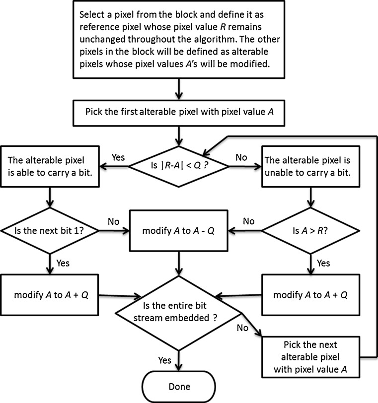
In this section, the reversible watermarking algorithm proposed in our earlier study [2] is presented. It consists of two stages (i.e., data embedding and data extraction). During the data embedding stage at the sender side, an image of W×H pixels to be watermarked is firstly divided into non-overlapping square blocks of size N×N, where 1 ≤ N ≤ min(W,H). In the case that W or H is not a multiple of N, the remaining part at the end of each block row or block column will be appended to the block to its left or above, respectively. A watermarking parameter, Q, is then defined to ensure that enough embedding capacity is available. Each N × N image block is subsequently processed according to the flowchart illustrated in Fig. 1 in a raster scan manner until the entire bit stream is embedded.
Fig. 1.
The watermarking flowchart
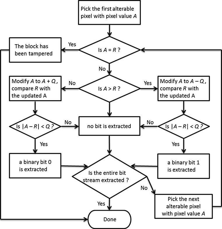
During data extraction stage (de-watermarking) at the receiver detector side, the watermarked image is firstly divided into non-overlapping blocks in the same way as at the sender side. Each block is subsequently processed according to the flowchart shown in Fig. 2 in a raster scan manner until the entire embedded bit stream is extracted. In this way, the watermarked image is converted back to the original image.
Fig. 2.
The dewatermarking flowchart
In our watermarking scheme, tamper-detection and localization information is embedded as the second watermark layer (which is the focus of this paper) after metadata is embedded as the first watermark layer.
Integrity Embedding for Tamper-Detection and Localization
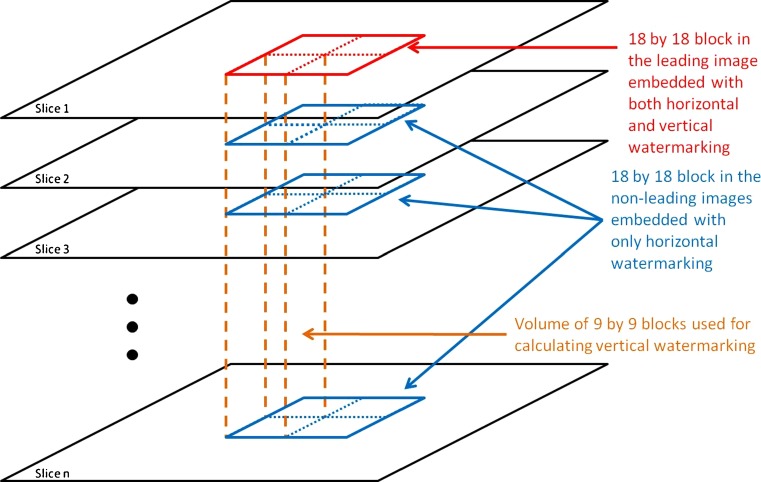
Integrity embedding for tamper-detection and localization is achieved by embedding error-detection data on every zoned image region in a reversible manner. To avoid the need to check every slice in a volume stack during dewatermarking and reduce the size of the localization region (improving localization resolution), a new scheme for tamper-detection and localization was developed. The scheme considers the first image slice in a volume stack as the leading image and the subsequent slices that follow as the non-leading images. The technique processes the leading image in a different manner from non-leading images: Each non-leading image is embedded only with horizontal CRC whereas the leading image is embedded with both horizontal CRC and vertical CRC. The purpose of the vertical CRC is to enable rapid checking of the overall integrity of the volume stack (without the need to check every single slice) while the horizontal CRC is to allow checking of the integrity of isolated regions within each image when the corresponding vertical CRC checking fails. The embedding structure is illustrated in Fig. 3. The details of the embedding process are described in the following sections.
Fig. 3.
The integrity embedding structure
Integrity Embedding for Non-leading Image
Non-leading image is embedded only with horizontal CRC. At the sender side, the image is firstly divided into non-overlapping large blocks (In this paper the terms “large block” and “small block” refer to a block of size 18 by 18 and a block of size 9 by 9, respectively). A watermarking parameter Q2 is then defined to ensure sufficient embedding capacity for the second watermark layer. One necessary condition to maintain a comparable embedding capacity to the first watermark layer is that Q2 ≥ 2 × Q1, where Q1 is the watermarking parameter of the first watermark layer and also the maximum difference between reference pixel and alterable pixel that can be extended by the embedding algorithm in the first watermark layer. The definitions of both Q1 and Q2 are also restricted by the underflow and overflow conditions, which will occur respectively in the case of DICOM images with 16-bit depth when the gray level of n is decreased by more than n or the gray level of 65535-n is increased by more than n. As a result, true 16-bit images would not be appropriate for the proposed algorithm. However, current medical imaging modalities generally do not produce images that utilize the full range of gray levels. Therefore, all the pixel values of the original image are increased by Q, where Q = Q1 + Q2, to avoid overflow and underflow conditions, and all the pixel values would eventually be decreased by Q to restore the original image at the receiver detector side. After defining Q2, each block of 18 by 18 pixels is subsequently processed in a raster scan manner according to the following steps.
Determine the embedding capacity C of the current block. Here, the embedding algorithm of reversible watermarking presented earlier was modified to determine C by considering the block as input image, segmenting it into square blocks with N = 3 and selecting central pixel of the 3 by 3 block as reference pixel. Pixels are then updated according to the following step: If |R-A| < Q, C = C + 1.
-
Decide the appropriate error detection code to be used based on the available embedding capacity which could be slightly lower than 16 in some regions of the image.
- If C ≥ 16, calculate the CRC-16-CCITT code of the block.
- If 12 ≤ C<16, calculate the CRC-12 code of the block.
Horizontal CRC code calculation is performed in this step. To reduce the computation time and to maintain tamper detection capability, the algorithm first generates a new block of 9 by 9 pixels from the original 18 by 18 pixels block. The 9 by 9 pixels block is obtained by summing the pixel values of every non-overlapping 2 by 2 pixels block within the 18 by 18 pixels block. Hence, each pixel in the 9 by 9 pixels block corresponds to the summation of a 2 by 2 pixels block in the 18 by 18 pixels block. The CRC code of the 9 by 9 pixels block is then calculated.
Perform the data embedding stage of the reversible watermarking algorithm presented in earlier section on the current block by considering the block as an input image (i.e., W = H = 18). Select the segmented square block size N to be 3. Select the central pixel as reference pixel for every block and use Q2 as the watermarking parameter Q.
The embedding process continues until 16 bits have been embedded in the case of CRC-16-CCITT or until the CRC bits are repeatedly embedded to fully occupy the embedding capacity in the case of CRC-12. Once step 4 is completed, block-based error-detection data are successfully embedded.
Integrity Embedding for Leading Image
With the aim to further reduce the processing time at the receiver detector side, the new concept of vertical watermarking was introduced. Through the use of the vertical watermarks, the receiver detector can quickly determine whether tampering has occurred in a particular narrow volume. In the case when there is no tampering, no further verification is required for each single image in the volume stack; while in the case when tampering has occurred, vertical watermarking would highlight that tampering has occurred in that narrow volume and further examination into the horizontal CRC codes that correspond to the vertical watermarks for each single image can locate the tamper more precisely. The leading image of the volume stack is selected to accommodate the vertical watermarks, in addition to its own horizontal CRC codes.
Using similar embedding technique as the non-leading image, the leading image is also firstly divided into non-overlapping blocks of 18 by 18 pixels. A third watermarking parameter Q3 is then defined to be 8 × Q1 to ensure sufficient embedding capacity for the second watermark layer. Similarly, all the pixel values of leading image are increased by Q, where Q = Q1 + Q3, to avoid overflow and underflow conditions. All the pixel values will eventually be decreased by Q to restore the original image at the receiver detector side. After defining Q3, each block of 18 by 18 pixels (referred as large block) is subsequently processed in a raster scan manner according to the following steps.
Calculate the CRC-16-CCITT code of the large block using the new technique as described in the step 2 for processing the non-leading image.
Divide the large block into four non-overlapping blocks of 9 by 9 pixels (referred as small block) and calculate the vertical CRC-8 code for each of the four narrow volumes where the four small blocks reside, respectively. Each narrow volume comprises a 9 by 9 pixels block from the leading image and a series of 9 by 9 pixels blocks from the subsequent non-leading images at the same horizontal coordinates (see Fig. 3). The vertical CRC code is calculated using the volume block of which each pixel value is the summation of all the pixels at the same horizontal coordinates across the volume.
Obtain the data bits to be embedded for each small block. The entire data bits consist of four data bits of the 16-bit horizontal CRC code of the large block as well as the entire eight-bit vertical CRC code of the volume where the small block resides.
Perform the data embedding stage of the reversible watermarking algorithm presented in earlier section on each small block by considering it as input image (i.e., W = H = 9). Select the segmented square block size N to be 3. Select the central pixel as reference pixel for every block and use Q3 as the watermarking parameter Q.
The embedding process continues until all 12 bits have been embedded for each small block.
Integrity Extraction
At the receiver detector side, the watermarked leading image is firstly divided into non-overlapping blocks of 18 by 18 pixels. Each block is subsequently processed in a raster scan manner according to the following steps.
Divide the large block into four small blocks in the same way as at the sender side.
Perform the data extraction stage of the reversible watermarking algorithm presented in earlier section on each small block by considering it as a watermarked image. Segment it into blocks of the same size (N = 3) as at the sender side.
The extraction process continues until 12 bits have been extracted for each small block. Based on the extracted data bits, obtain four extracted eight-bit vertical CRC codes for the four narrow volumes where the small blocks belong to and one extracted 16-bit horizontal CRC code for the leading image.
- For each small block, if the number of bits extracted is less than 12 or the extracted eight-bit vertical CRC code does not agree with the newly calculated vertical CRC code, the narrow volume where that block resides is identified as being tampered. Further examination on the large block of each non-leading image in the same volume as the large block of the leading image is required to determine the exact location of the tamper and is carried out as follows:
- Perform the data extraction stage of the reversible watermarking algorithm presented in earlier section on the current block by considering it as a watermarked image. Segment it into blocks of the same size (N = 3) as at the sender side.
- The extraction process continues until 16 bits, which are deemed to be the extracted horizontal CRC code, or until all the available bits have been extracted.
- If the number of bits extracted is larger than 11 but smaller than 16, the first 12 bits are deemed as the extracted horizontal CRC code.
- If the number of bits extracted is less than 12 or the extracted horizontal CRC code does not agree with the newly calculated horizontal CRC code of the restored image block, the intersectional small block of the tampered narrow volume identified earlier and the large block currently examined is identified as being tampered.
If each of the four volumes is identified as tamper-free, the large block of each non-leading image in the same large volume as the large block of the leading image is processed only using the data extraction stage of the reversible watermarking algorithm presented in earlier section without further verification on the extracted horizontal CRC code.
Using this algorithm, tampered areas are detected and localized or each image will be passed on to the extraction stage of first watermark layer. In the final stage, each original image is restored.
Performance Evaluation
The new methodology proposed in this paper was evaluated in terms of computational efficiency and robustness to tampering using four test sets of 3-D volumetric DICOM images with parameters summarized in the Table 1. The test images were MRI images of different anatomical structures. The evaluation was performed by running MATLAB (The Mathworks, Inc., Natick, MA, USA) programs on a laptop with dual-core CPU of 1.83 GHz and RAM of 2 GB. Higher computational efficiency is a vital factor of a practical solution, and hence both watermarking and dewatermarking time are compared between directly applying a 2-D method [2] and the new proposed method on 3D datasets. Robustness to tampering was evaluated by performing both systematic tampering and real case tampering. Systematic tampering was used to examine the tamper localization accuracy and tamper display resolution whereas real case tampering was used to assess the tamper detection and localization function from a medical practice point of view.
Table 1.
Parameters of test image sets
| Image set name | No. of images per volume set | Image dimensions in pixels | Bits per pixel |
|---|---|---|---|
| Knee | 48 | 256 × 256 | 12 |
| Shoulder | 56 | 256 × 256 | 12 |
| Heart | 16 | 256 × 256 | 8 |
| Brain | 20 | 256 × 256 | 10 |
Results
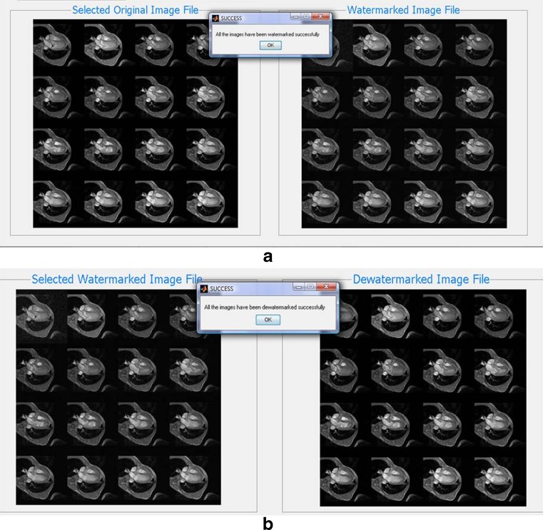
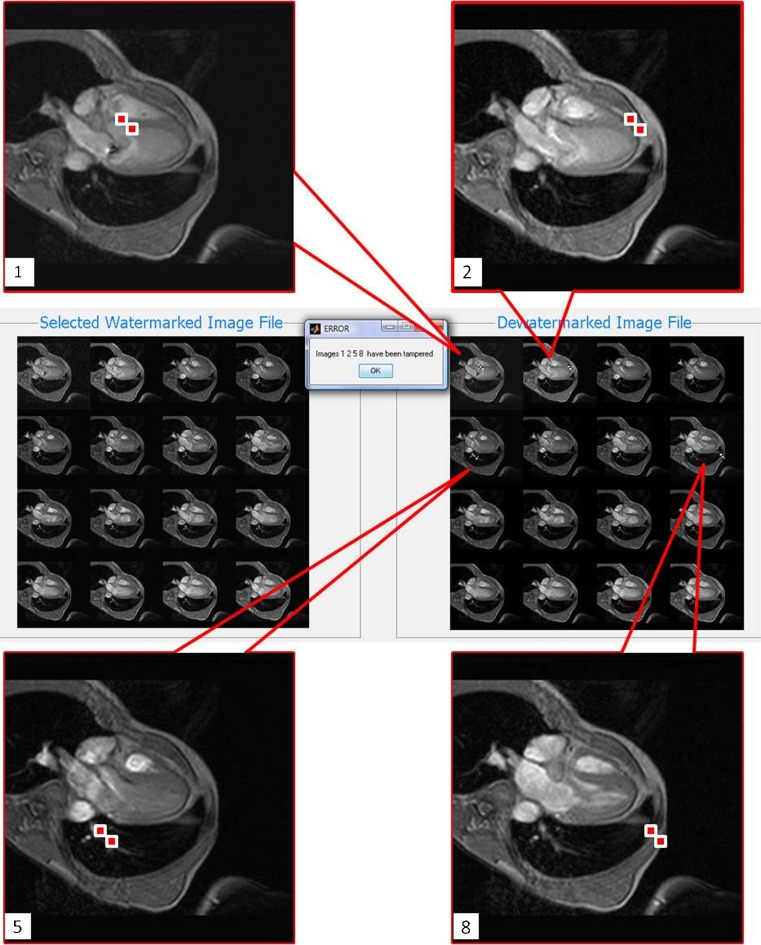
In this paper, we sought to greatly reduce the time in tamper detection processing and to improve tamper localization without compromising its ability to ensure authenticity. The focus was on the protection of volumetric DICOM images which comprises a number of 2-D images. The new technique was evaluated in terms of computational efficiency and robustness to tampering. A MATLAB program was developed based on the new method. Using the new program, it is possible to watermark and dewatermark all the test images using lesser processing time as compared with directly applying a 2-D method [2]. Figure 4 shows the sample results of successful watermarking and successful dewatermarking using the MATLAB program when there was no tampering. The program was also capable of detecting and localizing tampering performed on the test images. Sample result of successful tamper localization is shown in Fig. 5.
Fig. 4.
Screenshots of example results of a successful watermarking using MRI heart dataset and b successful dewatermarking using the same dataset. The right image of (a) and the left image of (b) are the same
Fig. 5.
Screenshot of sample result of successful tamper detection and localization with the tampered slices 1, 2, 5, and 8 enlarged. Tampered regions are highlighted with the red boxes
Computational Efficiency
Each DICOM image of the four test sets was used to evaluate computational efficiency, and all the images were watermarked and dewatermarked successfully in tamper-free circumstance. The processing time of each image from the test sets during the watermarking stage using the 2-D method and new method was recorded, and the average time for each set is listed in the Table 2. Results show that the new method achieved a significant reduction in watermarking time, an average of 65 % reduction. This result demonstrated that the new method has improved the computational efficiency of watermarking volumetric images, as compared with the 2-D method.
Table 2.
Comparison of watermarking time between 2-D method and proposed method
| Image set | Watermarking time per image using 2-D method (s) | Watermarking time per image using new method (s) | Reduction (%) |
|---|---|---|---|
| Knee | 1.6816 | 0.6086 | 63.81 % |
| Shoulder | 1.6514 | 0.5646 | 65.81 % |
| Heart | 1.5923 | 0.5452 | 65.76 % |
| Brain | 1.6037 | 0.5518 | 65.59 % |
The processing time of each image from the test sets during the dewatermarking stage using the 2-D method and new method was recorded, and the average time for each set is listed in the Table 3. Results show that the new method achieved a considerable reduction in dewatermarking time, an average of 72 % reduction. Compared with the percentage of reduction in the watermarking stage, the dewatermarking time was further improved by the use of vertical watermarking.
Table 3.
Comparison of dewatermarking time between 2-D method and proposed method
| Image set | Dewatermarking time per image using 2-D method (s) | Dewatermarking time per image using new method (s) | Reduction (%) |
|---|---|---|---|
| Knee | 1.7705 | 0.5113 | 71.12 % |
| Shoulder | 1.7792 | 0.4841 | 72.79 % |
| Brain | 1.6833 | 0.4836 | 71.27 % |
| Heart | 1.7060 | 0.4680 | 72.57 % |
The considerable computational efficiency improvement is a result of significant reduction in computational complexity of processing the second watermark layer where the new tamper detection and localization method was implemented. The number of add/multiply operations required for watermarking (i.e., to generate the CRC codes and embed them as a watermark) and dewatermarking (i.e., to retrieve and check the CRC codes) the second layer for the four test sets using direct 2-D method and the new method are shown in Tables 4 and 5, respectively. The results show that there was on average 60.4 % and 91.3 % reduction in the number of add/multiply operations during watermarking and dewatermarking, respectively.
Table 4.
Comparison of order of complexity of second layer watermarking between 2-D method and proposed method
| Image set | Number of add/multiply operations for watermarking the second layer per image using direct repetition of the 2-D method | Number of add/multiply operations for watermarking the second layer per image using the new method | Reduction (%) |
|---|---|---|---|
| Knee | 2,285,556 | 847,406 | 62.92 % |
| Shoulder | 2,285,556 | 837,396 | 63.36 % |
| Heart | 2,285,556 | 987,546 | 56.79 % |
| Brain | 2,285,556 | 945,504 | 58.63 % |
Table 5.
Comparison of order of complexity of second layer dewatermarking between 2-D method and proposed method
| Image set | Number of add/multiply operations for de-watermarking the second layer per image using direct repetition of the 2-D method | Number of add/multiply operations for de-watermarking the second layer per image using the new method | Reduction (%) |
|---|---|---|---|
| Knee | 2,285,556 | 142,982 | 93.74 % |
| Shoulder | 2,285,556 | 132,972 | 94.18 % |
| Heart | 2,285,556 | 283,122 | 87.61 % |
| Brain | 2,285,556 | 241,080 | 89.45 % |
These results show that the new method has effectively improved the watermarking computational efficiency by reducing the input size for horizontal CRC calculation and reduced the dewatermarking processing time and computational complexity by using the vertical watermarking technique, which makes the proposed scheme a better solution from practical point of view.
Robustness to Tampering
Systematic Tampering
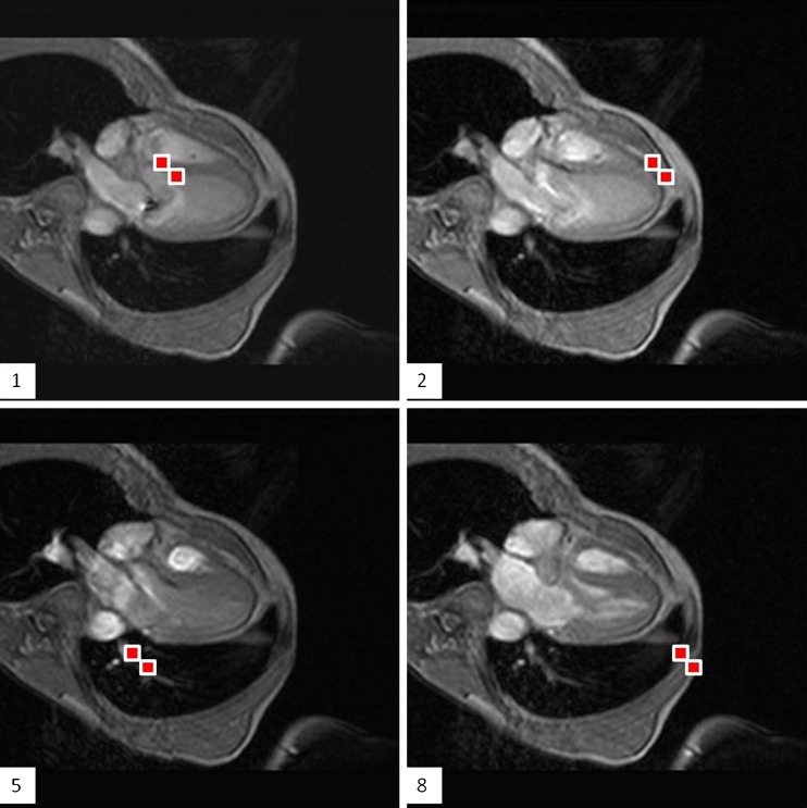
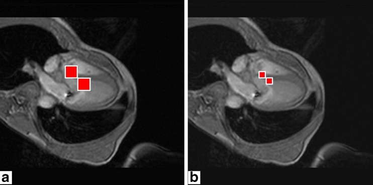
To verify the accuracy of the new tamper detection and localization scheme, systematic tampering of watermarked images includes tampering of a single pixel at random locations at randomly selected images in one volumetric set. This type of tampering was performed on each test set that has been watermarked by the new method. Four images were randomly selected, and each image was tampered at two random pixel locations using MATLAB. The new method achieved 100 % tamper localization accuracy for all the systematic tampering tests. The sample systematic testing results of successful tamper localization for the heart image set are shown in Fig. 6. Compared with the 2-D method, the new method displayed a much smaller tamper localization area as shown in Fig. 7. Consequently, a better resolution for examining the tamper was achieved.
Fig. 6.
Sample systematic testing results. Slices 1, 2, 5, and 8 of the MRI heart image set with tamper being localized using the new method. The red box in the image indicates where tamper has occurred
Fig. 7.
a Slice 1 of the MRI heart image set with tamper being localized using the 2-D method; each red box has the size of 18 by 18 pixels. b Slice 1 of the MRI heart image set with tamper being localized using the new method; each red box has the size of 9 by 9 pixels
Real Case Tampering
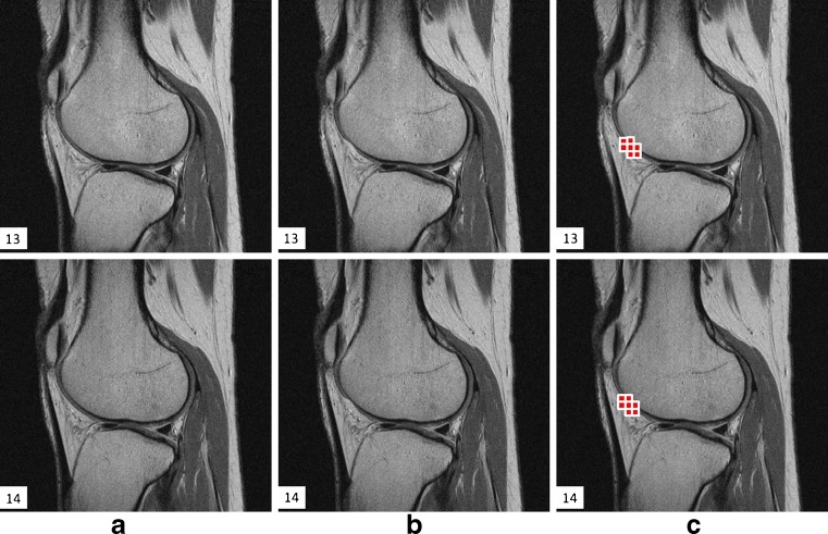
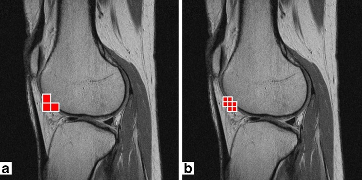
Real case tampering was performed to assess the capability of the proposed method in detecting and localizing the tampered regions. Real case tampering of watermarked images refers to tampering of image regions that are of clinical importance by a hacker with the intention to deceive the doctor. The set of knee MR images was used to evaluate the proposed scheme from this practical aspect. Tampering of 3-D volumetric dataset (e.g., CT, MRI) tends to be more difficult than tampering of single 2-D image (e.g., X-ray radiograph) because more images need to be altered in a consecutive manner so that the tampering will be more realistic. In this study, three consecutive slices from the knee set were altered by thinning the femoral cartilage to signify cartilage damage. The new method was able to detect and localize all the tampered regions in the test set. The sample results of the knee MR image set are displayed in Fig. 8. The real case testing results demonstrated that the new method of tamper detection and localization are competent for real-life scenarios in which at least a few pixels will be tampered to realistically deceive the reader. Furthermore, compared with the result of tamper localization using the 2-D method (as shown in Fig. 8a), the new method shows that it can confine the tamper area into a smaller localization region by adopting a smaller displaying block of 9 by 9 pixels, as shown in Fig. 9.
Fig. 8.
Real case tamper localization results. a Watermarked slices 13 and 14 of the knee MR image set; b watermarked slices 13 and 14 of the same set with tamper present; c slices 13 and 14 with tamper being localized using the new method
Fig. 9.
a Slice 14 of the knee MR image set with tamper being localized using the 2-D method; each red box has the size of 18 by 18 pixels; b slice 14 of the knee MR image set with tamper being localized using the new method; each red box has the size of 9 by 9 pixels
Discussion
A new and improved tamper-detection and localization method has been implemented and evaluated. The method was developed using a fully reversible digital watermarking scheme [2]. Using the proposed method, the computational efficiency of the watermarking algorithm was greatly improved. This overall improvement makes it more viable to be used in a practical medical environment.
This paper introduces the concept of vertical watermarking which exploits the 3-D characteristics of volumetric dataset to reduce processing time and computational complexity during dewatermarking and to improve the tamper localization resolution. The introduction of vertical watermarking brings forward benefits in three aspects at the expense of small increment in the watermarking time; however, the increment is considered trivial compared with the decrement resulting from the new method of calculating horizontal CRC and the new dewatermarking technique for tamper detection. Firstly, it further decreases the dewatermarking time by avoiding multiple horizontal CRC checking for non-leading images in tamper free condition. Secondly, the scheme can even detect whether there are missing slices with the help of vertical watermarking, which cannot be achieved by directly applying the 2-D method. Lastly, in the situation where tampering occurs, the scheme can provide a smaller localization display area. Consequently, the resolution of localization is improved. Although CRC was used in our method, it is possible to adopt the same concept of using horizontal and vertical watermarks with other types of error verification codes (e.g., digital signature), although the block size might have to be different to accommodate the size of the codes.
An analysis of the number of add/multiply operations required for watermarking and dewatermarking the second layer for the four test sets by directly applying the 2-D method and using the proposed method was performed. The results show that there is large reduction in number of add/multiply operations during watermarking and dewatermarking, respectively, using the proposed method. This paper proposed a 3-D method to protect 3-D volumetric images with tamper detection and localization functionality, as opposed to applying the existing 2-D methods naively and repetitively on the 3-D volumetric image, slice by slice, which is inefficient. It is worth noting that the concept proposed in our 3-D method could also be applied to the other 2-D methods to enable them to handle 3-D volumetric images efficiently.
We have incorporated three tamper-detection checks (vertical CRC, horizontal CRC, and the hash of the original image) in the proposed watermarking scheme to ensure a low probability that both tamper-detection and localization will fail. The probability of success of the proposed tamper-detection and localization method mainly depends on both the strength of the vertical CRC code embedded in the second watermark layer of the leading image and the strength of the Secure Hash Algorithm (SHA-256) hash of the original image embedded in the first watermark layer of all images in the stack. During dewatermarking, the vertical CRC will first be checked. If all vertical CRC checks do not detect tampering, the hash of the original image will still be checked to ensure the overall integrity of the image. This is to ensure that failure of tamper detection will only occur in the case when both the vertical CRC checks and SHA hash checks fail to detect tampering. In the case when the vertical CRC code fails to detect tampering while SHA hash detects tampering, the proposed method still has the tamper-detection capability. Furthermore, once the SHA hash check detects tampering, the horizontal CRC could next be used to localize the tampered regions. If this horizontal CRC also fails to detect tampering, then tamper localization has failed, but we still consider that tamper-detection is successful, and an alarm can be flagged to alert the user. In the rare case that both vertical CRC and SHA hash fail to detect tampering when tampering has occurred, we consider that the proposed method has failed to detect tampering, however, it should be clear by now that such occurrence will be extremely rare.
It is worthy to note that MATLAB programming language was selected for the purpose of testing in this study. C++ programming can be used to implement real-time software to speed up the process. Moreover, the power of parallel computing can be utilized in the future to process 3-D volumetric medical images, which allows further improvement of computational efficiency.
Conclusion
This paper presents a tamper-detection and localization algorithm that is designed with the specific aim to minimize the computational complexity and to achieve improved computational efficiency without unduly compromising the protection and tamper localization capabilities for volumetric DICOM images. The improved processing time makes the proposed scheme a more viable solution than to directly and iteratively apply 2-D method for securing 3-D DICOM medical images in real-life medical environment.
Reference
- 1.Digital Imaging and Communications in Medicine (DICOM) Standard. Available at [Online]. Available: http://medical.nema.org/dicom/2006/2006
- 2.Tan CK, Ng JC, Xu X, Poh CL, Guan YL, Sheah K. Security protection of dicom medical images using dual-layer reversible watermarking with tamper detection capability. Journal of Digital Imaging. 2011;24:528–540. doi: 10.1007/s10278-010-9295-4. [DOI] [PMC free article] [PubMed] [Google Scholar]
- 3.Zhou XQ, Huang HK, Lou SL. Authenticity and integrity of digital mammography images. IEEE Trans Medical Imaging. 2001;20:784–791. doi: 10.1109/42.938246. [DOI] [PubMed] [Google Scholar]
- 4.Macq B, Dewey F. Trusted headers for medical images. Erlangen: DFG VIII-DII Watermarking Workshop; 1999. [Google Scholar]
- 5.Zain JM, Fauzi ARM: Medical image watermarking with tamper detection and recovery. Proc. Engineering in Medicine and Biology Society, 2006 EMBS ‘06 28th Annual International Conference of the IEEE: City, Aug. 30 2006-Sept. 3 2006 Year [DOI] [PubMed]
- 6.Guo X, Zhuang T. A region-based lossless watermarking scheme for enhancing security of medical data. Journal of Digital Imaging. 2009;22:53–64. doi: 10.1007/s10278-007-9043-6. [DOI] [PMC free article] [PubMed] [Google Scholar]
- 7.Guo X, Zhuang T. Lossless watermarking for verifying the integrity of medical images with tamper localization. Journal of Digital Imaging. 2008;22:620–628. doi: 10.1007/s10278-008-9120-5. [DOI] [PMC free article] [PubMed] [Google Scholar]
- 8.Wu JHK, et al. Tamper detection and recovery for medical images using near-lossless information hiding technique. Journal of Digital Imaging. 2008;21:59–76. doi: 10.1007/s10278-007-9011-1. [DOI] [PMC free article] [PubMed] [Google Scholar]
- 9.Vleeschouwer C, Delaigle J-F, Macq B. Circular interpretation of bijective transformations in lossless watermarking for media asset management. Multimedia, IEEE Transactions on. 2003;5:97–105. doi: 10.1109/TMM.2003.809729. [DOI] [Google Scholar]
- 10.Lim SJ, Moon HM, Chae SH, Pan SB, Chung Y, Chang MH. Dual watermarking method for integrity of medical images. Proc IEEE FGCN Conf, Hainan Island. 2008;2:70–73. [Google Scholar]
- 11.Zain JM, Baldwin LP, Clarke M. Reversible watermarking for authentication of DICOM images. Proc IEEE EMBS Conf, San Francisco, CA. 2004;2:3237–3240. doi: 10.1109/IEMBS.2004.1403911. [DOI] [PubMed] [Google Scholar]
- 12.Fridrich J, Goljan M, Du R. Lossless data embedding—new paradigm in digital watermarking. EURASIP Journal on Applied Signal Processing. 2002;2002:185–196. doi: 10.1155/S1110865702000537. [DOI] [Google Scholar]
- 13.Coatrieux G, Maitre HBS. Strict integrity control of biomedical images. Proc SPIE Security Watermarking Multimedia Contents III, San Jose, CA. 2001;4314:229–240. [Google Scholar]
- 14.Coatrieux G, Lamard M, Daccache W, Puentes W, Roux C: A low distorsion and reversible watermark: application to angiographic images of the retina. Proc IEEE-EMBS Engineering in Medicine and Biology Society:2224-2227, 2005 [DOI] [PubMed]
- 15.Chiang KH, Chang-Chien KC, Chang RF, Yen HY. Tamper detection and restoring system for medical images using wavelet-based reversible data embedding. Journal of Digital Imaging. 2008;21:77–90. doi: 10.1007/s10278-007-9012-0. [DOI] [PMC free article] [PubMed] [Google Scholar]
- 16.Lee S, Yoo CD, Kalker T. Reversible image watermarking based on integer-to-integer wavelet transform. IEEE Trans Inf Forensics Security. 2007;2:321–330. doi: 10.1109/TIFS.2007.905146. [DOI] [Google Scholar]
- 17.Coatrieux G, Guillou CL, Cauvin J-M, Roux C. Reversible watermarking for knowledge digest embedding and reliability control in medical images. IEEE Trans Inf Technol Biomed. 2009;13:158–165. doi: 10.1109/TITB.2008.2007199. [DOI] [PubMed] [Google Scholar]
- 18.Fotopoulos V, Stavrinou ML, Skodras AN: Medical image authentication and self-correction through an adaptive reversible watermarking technique. Proc IEEE BIBE Conf, Athens:1-5, 2008
- 19.Coatrieux G, Montagner J, Huang H, Roux C: Mixed reversible and RONI watermarking for medical image reliability protection. Proc IEEE EMBS Conf, Lyon:5653-5656, 2007 [DOI] [PubMed]


