

Abstract
Purpose: This study presents the implementation and experimental results of a novel technique for 4D tumor tracking using a commercially available and commonly used treatment couch and evaluates the tumor tracking accuracy in clinical settings.
Methods: Commercially available couch is capable of positioning the patient accurately; however, currently there is no provision for compensating physiological movement using the treatment couch in real-time. In this paper, a real-time couch tracking control technique is presented together with experimental results in tumor motion compensation in four dimensions (superior-inferior, lateral, anterior-posterior, and time). To implement real-time couch motion for tracking, a novel control system for the treatment couch was developed. The primary functional requirements for this novel technique were: (a) the treatment couch should maintain all previous/normal features for patient setup and positioning, (b) the new control system should be used as a parallel system when tumor tracking would be deployed, and (c) tracking could be performed in a single direction and/or concurrently in all three directions of the couch motion (longitudinal, lateral, and vertical). To the authors’ best knowledge, the implementation of such technique to a regular treatment couch for tumor tracking has not been reported so far. To evaluate the performance of the tracking couch, we investigated the mechanical characteristics of the system such as system positioning resolution, repeatability, accuracy, and tracking performance. Performance of the tracking system was evaluated using dosimetric test as an endpoint. To investigate the accuracy of real-time tracking in the clinical setting, the existing clinical treatment couch was replaced with our experimental couch and the linear accelerator was used to deliver 3D conformal radiation therapy (3D-CRT) and intensity modulated radiation therapy (IMRT) treatment plans with and without tracking. The results of radiation dose distribution from these two sets of experiments were compared and presented here.
Results: The mechanical accuracies were 0.12, 0.14, and 0.18 mm in X, Y, and Z directions. The repeatability of the desired motion was within ±0.2 mm. The differences of central axis dose between the 3D-CRT stationary plan and two tracking plans with different motion trajectories were 0.21% and 1.19%. The absolute dose differences of both 3D tracking plans comparing to the stationary plan were 1.09% and 1.20%. Comparing the stationary IMRT plan with the tracking IMRT plan, it was observed that the central axis dose difference was −0.87% and the absolute difference of both IMRT plans was 0.55%.
Conclusions: The experimental results revealed that the treatment couch could be successfully used for real-time tumor tracking with a high level of accuracy. It was demonstrated that 4D tumor tracking was feasible using existing couch with implementation of appropriate tracking methodology and with modifications in the control system.
Keywords: tumor tracking, robotic couch, tumor motion compensation
INTRODUCTION
About 226 160 new cases of lung cancer are expected in 2012, accounting for 14% of cancer diagnoses.1 Lung cancer accounts for more deaths than any other cancer in both men and women. An estimated 160 340 deaths, accounting for about 27.8% of all cancer deaths, are expected to occur in 2012.1
Tumors in the lung and other organs in the thoracic and abdominal regions may move up to 2–3 cm during breathing cycles and cardiac motion.2, 3, 4 There are clinical evidences of local control and survival advantage for lung cancers, especially treating with higher dose levels.4 Therefore, intrafraction motion management and related treatment margins are becoming increasingly important in the context of sparing healthy tissues and adjacent critical structures. This necessitates precise irradiation of the target volume while minimizing dose to healthy tissues by compensating for physiological movements.
In recent years, the investigation of various aspects of tumor motion management and development of tools to deliver precise dose to moving target volumes have attracted significant attention in the scientific community. Many studies on tumor tracking have been published in the past decade.5, 6, 7, 8, 9, 10, 11, 12, 13, 14, 15, 16, 17, 18, 19, 20, 21, 22, 23, 24, 25, 26, 27, 28, 29, 30, 31
There are various techniques currently available for monitoring and controlling or compensating respiratory motion during radiation therapy. These methods are: slow CT scanning, inhale and exhale breath-hold CT imaging, or 4D CT/respiration-correlated CT, gating using an external respiration signal, gating using internal fiducial markers. Breath-holding methods are deep-inspiration breath-hold, active-breathing control, and self-held breath-hold without respiratory monitoring. Also, forced shallow breathing with abdominal compression is a commonly used approach. It is also possible to employ real-time tumor tracking to compensate for tumor movement. However, none of these methods is perfect; different methods have different types of drawbacks. For example, imaging and planning cannot be done in real-time in a strict sense, 4D CT imaging requires adequate respiratory motion patterns; the respiratory gating technique suffers from severely truncated duty-cycle of radiation delivery; breath-hold method requires the patient to be trained (uncomfortable, particularly for patients with compromised pulmonary capacity); hypo-oxygenation due to breath-hold may reduce the effectiveness of the killing of cancerous cells; shallow-breathing with abdominal compression is uncomfortable for the patient and may also affect tumor oxygenation.4
Aside from the traditional methods for the tumor motions compensation, such as breath-hold and gating, another direction of scientific investigation involves real-time tumor motion compensation and dynamic dose delivery. Real-time tumor tracking, sometimes called active tracking and dynamic delivery (ATDD),5, 20, 22, 23, 24, 25 can be accomplished in three different ways: (a) adjusting the multileaf collimator (MLC), (b) adjusting the couch, and (c) adjusting the MLC and the couch simultaneously. Determination of the accuracy of dynamic multileaf collimator (DMLC) tracking received significant attention.9, 10, 11 Preliminary work on tumor motion compensation using robotic couch was reported by several research groups.19, 20, 21, 22 In this approach, the robotic treatment couch moves during delivery of the radiation beam and compensates for breathing-induced tumor motion. D’Souza and McAvoy performed an analysis of the couch dynamics and control systems in order to provide an estimate of the design specifications that would be required for effective motion compensation of respiration-induced lung and abdominal tumors exhibiting motion displacements of up to 3 cm using the treatment couch.19 In our previous work, the tumor motion trajectory was decomposed and allocated to the various subsystems (MLC-bank and robotic couch) based on their natural frequency domains using a wavelet technique.20 Putra et al. considered a compensation strategy for tumor motion caused by respiration and patient movements during radiotherapy treatments using a controlled patient support system (PSS) and an output-feedback model with a predictive control scheme.21 Detailed dynamic-based control scheme with a prediction module for commercially available treatment couches was presented in our previous work.22, 23 In these studies, a prediction module was developed to predict tumor motion and to compensate errors due to the delay in the system response. The simultaneous usage of MLC and couch for tumor motion compensation has been presented in several publications.5, 20, 24 During real-time tracking several parameters of the control system, such as patient mass and breathing pattern, are initially uncertain and may vary during the course of treatment. To solve these problems, feed-forward adaptive control was adopted to minimize irradiation to the healthy tissue and spare critical organs.25
Implementation of the couch motion for tumor motion compensation may pose additional problems or discomfort to patients under treatment. Several studies have addressed and investigated whether patients could tolerate the motion of the treatment couch that would compensate for the breathing-induced tumor motion.26, 27, 28 Among 4800 responses, the results show that the patients do not suffer from motion sickness or external surface instability on a moving couch.26 Sweeney et al. concluded that the patients tolerated the compensatory couch motion, and motion sickness should not pose a problem in the investigation of different tumor tracking methods.27 The influence of continuous couch motions on patient breathing patterns for the compensation of moving targets by a robotic treatment couch was investigated, and it was found that the continuous couch motion was well tolerated by all test subjects.28 Several researchers reported dosimetric justification and potential advantages of tumor tracking.29, 30, 31
Based on these published research and clinical investigations, the importance of developing tracking techniques is well established. Implementation of real-time tracking techniques can minimize irradiation to healthy tissues and improves sparing of critical organs. Consequently, quality of patient treatment can potentially be improved.
In this paper, an adaptation of a commercial treatment couch for simultaneous tracking in three dimensions is demonstrated. In Secs. 2, 3, 4, 5, the novel control methodology necessary for real-time tracking is presented. A brief description of the system integration for tracking tasks has been provided. To evaluate the system performance, several experimental studies have been performed, including couch performance tests, mechanical tests, and dosimetry tests of tumor tracking using external radiation beam.
MATERIALS AND METHODS
Commercially available couch is capable of positioning the patients accurately; however, currently there is no provision for compensating physiological movement using the treatment couch in real-time.23 In this study, an existing commercially available treatment couch Elekta Precise Table™ (EPT) (ELEKTA Ltd., Crawley, UK) was used without changing its design. To establish the couch motion for real-time tracking, a novel control system for the treatment couch was developed and implemented. The basic functional requirements for the implementation of this technology are: (a) the treatment couch should maintain all existing standard/regular features for patient setup and positioning, (b) the new control system should be used as a parallel system when tumor tracking is deployed, and (c) tracking should be performed with single axis motion and/or simultaneously in multiple directions of the couch/tumor motion (longitudinal, lateral, and vertical). The X direction is defined as the couch longitudinal or patient's superior-inferior direction, Y is the couch/patient lateral direction, and Z is the couch vertical and patient's anterior-posterior direction.32
Dynamic equations
The first step was to develop the dynamic equations of motion for EPT using energy based Euler-Lagrange formulation.23 These equations were essential in developing a dynamics-based coordinated feedback control system. The equations of motion were used to determine the appropriate ranges for proportional, integral, and derivative (PID) control gains and the filter parameters.
The EPT is an integral part of the system for radiation therapy (Fig. 1). EPT consists of a two degree-of-freedom (DOF) tabletop and a one DOF vertical lift. The vector of generalized coordinates q for the EPT was chosen as follows: vertical motion of the couch s, relative motion of the tabletop ξ and η. Consequently, q = (s ξ η)T. The schematic view of the system is shown in Fig. 1. Referring to the figure, a fixed coordinate system was assigned as (x y z) at the center O of the point where the couch is connected to the floor. The moving coordinate system (ξ η ζ) at the center C is attached to the tabletop. The vertical direction motor (mass M) drives the ball screws, which are responsible for the vertical motion of the mechanism in z direction with respect to Oxyz coordinate system. The end of the upper moving rod (length L, mass m2) is fixed to a tabletop holder [Fig. 1c]. Both the lower and upper moving rods are of the same length.
Figure 1.

Schematic view of ELEKTA Precise Table™: (a) and (b) Internal isometric view, (c) System model: vertical movement in s direction is achieved by motor installed in the holder A. Tabletop movement in ξ and η directions are achieved by two motors sitting bellow the tabletop.
The tabletop (mass m, including load) effectuates a plane motion in Cξηζ coordinate system. The motion of the mechanism is analyzed with respect to the fixed coordinate system Oxyz. The tabletop moves in ξ and η directions with respect to the coordinate system Cξηζ. Coordinate system Cξηζ is fixed to a couch holder. The couch holder's vertical motion induces changes of the generalized coordinate s. Lengths a and b are geometric characteristics of the mechanism. Angle φ is variable and its change implies changes of the generalized coordinate s.
In Sec. 2A, 2B, only a limited number of key equations have been presented. The geometric relations and velocities used for the following derivation as well as more detailed derivations were presented in other publications.22, 23
The Lagrangian function of dynamic systems can be expressed as
| (1) |
The general form of dynamic equations is
| (2) |
where q ∈ Rn, and τ is the generalized force (or torque) applied to the system through the actuators. The final expression for the potential energy is
| (3) |
The total kinetic energy of the system is
| (4) |
where the kinetic energies of the moving rods OA and AC, the motor at point A, and the tabletop were denoted as TOA, TAC, Tmotor, and Ttt, respectively.
Combining the above Eqs. 1, 2, 3, 4, the general equations of motion for EPT were as follows:
| (5) |
The equations of motion 5 fully describe the dynamical behavior of the EPT. The force which is responsible for the translational motion of the axis ξ is denoted by τξ. The force which is responsible for the translational motion of the axis η is denoted byτη and vertical force is denoted by τM. In what follows, it will be denoted as system dynamics.
Control methodology
The purpose of the control methodology is to allow both modes of operations, i.e., use of the couch for patient positioning and tumor tracking. During patient positioning the couch should maintain all standard functions as in regular clinical use. Additionally, during radiation treatment, the couch should perform real-time tracking of the tumor. By the term real-time tracking, we refer to tracking in all three directions together with temporal variation, which is 4D tracking.
The block diagram and control methodology are presented in Fig. 2. The controller DMC-41×3 (Galil 3 Axis Controller, Galil Motion Control, CA with 500 mA sourcing outputs) provides two communication channels: a high-speed 100BaseT Ethernet connection and a USB programming port. The controllers allow for high-speed servo control up to 15 × 106 encoder counts/s and step motor control up to 3 × 10⁶ steps per second. The controller eliminates jerk by programmable acceleration and deceleration with profile smoothing. These characteristics allow adjusting the system for both best patient's comfort during tracking and accurate motion trajectory tracking.
Figure 2.
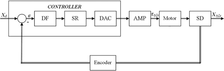
Functional elements of tumor tracking control system; DF: digital filter; SR = ZOH signal reconstruction; DAC: digital to analog converter. The ZOH, or zero-order-hold, represents the effect of the sampling process, where the motor command is updated once per sampling period. The DAC or D-to-A converter converts a 16-bit number to an analog voltage.
The digital filter has three elements which are responsible for the treatment couch control. These elements are the PID, low-pass, and a notch filter. The dynamic-based controller was proposed and explained in details in another publication.23 To reduce any steady-state error, an integral control part was also incorporated. Thus, the final control equation becomes
| (6) |
where KD, KP, and KI are the derivative, proportional, and integral gains, respectively. Equation 6 ensures asymptotic decay of the transient errors as well as the reduction of the steady-state errors. The gains were calculated to cancel the resonance effect during tracking by placing the complex zeros on the top of resonance poles of the system in Fig. 2. For instance, low-pass and PID elements have transfer function 7
| (7) |
In expression 7, z is the time parameter in the Laplace domain, and P = KP, D = TKD, I = KI/T, a = 1/Tln(1/B), T is the sampling period, and B is the appropriate pole setting which guarantees the system stability during tracking.
In Sec. 2B, two motion compensation techniques are described. The first is tumor tracking without knowing the tumor position in advance (tracking mode), and the second is the adaptive mode, when the trajectory is known before the treatment starts. In another word, if the motion trajectory was obtained in real-time during patient treatment using external/internal marker, the controller works in the tracking mode. The adaptive mode is the one when the motion trajectory was defined prior to the treatment (for instance, using 4D CT).
For online tumor tracking, the controller should be placed in the tracking mode to support changing position of the target volumes (absolute position change) during the treatment. The controller then calculates a new trajectory based upon the new target and acceleration, deceleration, and speed parameters that have been set. The controller updates the position information at the rate of 1 ms. The controller generates a profiled point for every other sample, and linearly interpolates one sample between all profiled points. Based on the tumor velocity and position, the controller either sends the signals to continue in the direction to where it is heading, or changes the direction where it moves, or decelerates to a stop. The position-tracking mode is suitable in the case when the internal markers give the real-time position during motion compensation and tracking. In that case, the proposed system is able to generate the tracking couch trajectory on the fly. The implemented tracking mode allows arbitrary motion profiles to be defined by position, velocity, and time for the individual motion trajectories. By specifying the target position, velocity and time to achieve the parameters, the user has control over the velocity profile of the system motion. Taking advantage of the builtin buffering the user can create virtually any profile and consequently, the system is able to perform tracking for a variety of motion profiles. Furthermore, using one of the tracking modes and the control strategy, it is possible to program desired motion for tracking. The controller interpolates the motion profile between the subsequent positions using a third-order polynomial equation, which is an inbuilt interpolation method of the control card used. The decomposed motion of the tumor centroid, tracking couch, and relative tumor motion position were presented in Fig. 3a, 3b, 3c.
Figure 3.

(a) The decomposed tumor centroid, (b) couch, and (c) tumor relative motions in absolute coordinate system in the tracking mode. Data show one representative case for breathing cycle of 6 s in X, Y, and Z directions. The trajectories represent real patient tumor motion.
The couch motion of any axis will not start unless the appropriate command is given from the control computer interface. It will ensure that all axes start the motion simultaneously. However, it is not necessary that all axes have the same time stamp, i.e., for demanding motion trajectories time delay in any direction can be implemented if needed. The tracking system was designed to control the errors using the encoders. The controller then performs in the following manner: the motion can be maintained or fully stopped, and with the proper interface with the linear accelerator, the radiation beam can be interrupted. The velocity profiles can be smoothened in order to reduce the couch vibrations.
System integration
To apply the dynamic-based control of the system to the EPT, system dynamics equation 5 has been used. The tabletop can move in the horizontal plane (laterally and longitudinally) using two Maxon 24 V motors with gearbox combination. The vertical motion is obtained using a robust 70 V Rockwell Automation motor. To obtain the exact position of the couch, the Baumer ITD 01 (4 mm shaft) encoders for X and Y motions were used, and the Model 755A Accu-Coder encoder for Z motion was used. The encoders were connected to the Advance Motion Controls amplifiers (AMC 20A20-INV amplifier for Z direction, and two AMC Z6A8 amplifiers for X and Y direction) to the Galil DMC-4133 controller for all three axes. The system has two independent power supplies: the Galil PSR-12-24 12A, 24 vdc power supply with diodes for controller, 24 V motors and amplifiers, and the Galil PS300W72 72 vdc power supply for vertical motion. The controller consisted of a new control algorithm developed for closed-loop control of the system using the position and velocity feedback. The equipment [Fig. 4a] has been mounted on the commercially available EPT [Fig. 4b]. The connection of the horizontal plane encoders to the controller was obtained by a 26 pin HD D-Sub female connector, whereas for the vertical motion encoder a CS-48044 M 44 pin connector was used. The AMC 20A20-INV amplifier for the Rockwell Motor is designed to drive brush type dc motors at a high switching frequency. The drive is fully protected against overvoltage, undervoltage, overcurrent, overheating, and short-circuits across motor, ground, and power leads. The X and Y encoders were mounted using the flexible mounting system which is tolerant to axial misalignment or radial shaft runout. The Z encoder was mounted on the vertical Rockwell motor using an inhouse made connector, as shown in Fig. 5a.
Figure 4.

(a) Control system integration parts, (b) ELEKTA Precise Table™ robotic treatment couch—experimental setup with reference coordinate system.
Figure 5.

(a) Installation of the encoder to vertical lift motor. Inset shows the adapter and holder for encoder. (b) Installation of the encoder for longitudinal couch motion (X direction). Inset represents the encoder mounting to the existing motor.
Experimental setup
Couch performance test
To evaluate the performance of the modified treatment couch, we investigated the mechanical characteristics of the system such as system resolution, repeatability, accuracy, and tracking using the maximum couch speed (45 mm/s). For these tests, the encoders’ reading, high-resolution camera, and vernier caliper were used. The couch was moved in the predefined positions using different speed up to the maximum speed for the motion in all three directions.32 The tests were performed using the nominal system resolutions of 1/3600 mm in X and Y directions and 1/1200 mm in Z direction.
Tumor tracking test—Mechanical
For simultaneous tracking in all three dimensions, the MotionSim XY/4D (Sun Nuclear Corporation, Melbourne, FL), a motion phantom, was used. The maximum speed of the motion phantom was 50.8 mm/s in X and Y directions, and 12.7 mm/s in Z direction. The approach was to use a phantom to simulate tumor motion, and to use the couch to compensate it. The motion phantom is designed to have independent 2DOF X and Y motions, and one DOF vertical motion. Additionally, we used the AlignRT 3D camera and real-time tracking system (VisionRT, London, UK) to evaluate the 4D motion, and to independently check the motion in Z direction. The AlignRT was used via surface imaging of the motion phantom.
The 4D MotionSim phantom was placed on the top of the couch, shown in Fig. 6a, and was programmed to move simulating the tumor motion. The metal plate with 2 mm holes was installed on the top of the 4D phantom. The camera was fixed from the side to record the black dot [Fig. 6b] on the wall, which appeared stationary and visible during the time when both the couch and phantom moved. Consequently, to keep the absolute position of the dot stationary/stable, the couch was moved in the opposite direction, as if to create the scenario where the tumor appears stationary with respect to the radiation beam. The images were then analyzed for evaluating tracking performance. The experiments were performed taking the system latency of 100 ms into account.
Figure 6.

(a) Experimental setup: Sun Nuclear programmable 4D phantom on the top of the couch, (b) The metal plate with the hole was fixed on the top of the 4D phantom.
Tumor tracking test—Dosimetry with external radiation beam
To investigate the feasibility of real-time tracking in the clinical setting, the existing treatment couch was replaced with our experimental couch (Fig. 7). The motion phantom was installed on the top of the couch, and the MapCheck (Sun Nuclear Corporation, Melbourne, FL) was placed and secured on the top of the motion phantom. The motion of the couch and phantoms was monitored using the AlignRT imaging system, as shown in Fig. 7. The couch was programmed to countermove relative to the motion phantom so the MapCheck appeared stationary with respect to the radiation beams. The first tumor motion trajectory was as shown in Fig. 3, with 6 s breathing cycles and a maximum breathing extent of 30 mm in Y direction. An additional tumor motion trajectory with a breathing cycle of 7.5 s and 20 mm maximum motion in X direction was also considered. The tumor motion trajectories were obtained from 4D CT scans of real patients. The two different lung plans (a 3D-CRT plan and an IMRT plan) were delivered first in a conventional manner, i.e., without compensating for tumor motion, and then with tumor motion compensation.
Figure 7.

Experimental setup of the tumor motion compensation system.
RESULTS
Couch performance test
It was noticed that with heavy load (100 kg) on the couch there were motion dead-zones of 0.1 mm in X and Y and 0.2 mm in Z direction. However, this issue did not influence the overall system performance. The accuracies for the linear range of motion of 200 mm in X, Y, and Z were 0.10 (SD = 0.10), 0.10 (SD = 0.10), and 0.12 (SD = 0.13) mm, respectively. The repeatability test demonstrated the same level of accuracy for ten consecutive motions in the positive and negative direction. The system was able to change the velocity successfully from 1 to 45 mm/s and back from 45 to 1 mm/s without motion interruptions within 4 s with maximum load. Based on these tests, it can be concluded that the modified treatment couch can potentially perform the tracking task.
Tumor tracking test—Mechanical
The system was tested for real-time tracking in the range of 50 mm in all 3 directions (superior-inferior, lateral, anterior-posterior). The accuracies were 0.12, 0.14, and 0.18 mm, respectively. The repeatability of the desired motion during trajectory tracking was within ±0.2 mm. The test motion profile of the tabletop in X and Y directions are shown in Fig. 8. It was observed that the relative motion of the metal plate (Fig. 6) was successfully canceled by the longitudinal and lateral motions of the couch, even in the transition moments when the direction, motion amplitude, and velocity were changed. Using the AlignRT system, it was observed that the vertical lift tracked the predefined trajectory with a maximal error of ±0.3 mm.
Figure 8.

Couch motion in X and Y direction for the tumor tracking test.
Tumor tracking test—Dosimetry with external radiation beam
Using the setup described in Sec. 2D3, a reference plan without the motion, i.e., both the tumor (a mass in the 4D phantom) and the couch were stationary, was initially delivered for a lung 3D conformal plan. Later, additional plans were delivered for two motion trajectories, shown in Fig. 3. The central axis (CAX) dose for the reference plan was 213.75 cGy, whereas the CAX doses for other two plans were 213.24 cGy and 210.94 cGy (0.21% and 1.19% difference). The doses in inplane and crossplane profiles were in the same range as in the CAX doses [Figs. 9a, 9b]. However, comparing all delivered plans with the computed plan from the treatment planning system, using the 3 mm distance-to-agreement and a 3% dose difference, it was observed that all plans were within the 2% absolute difference. The passing rate of the stationary plan comparing to the reference one was 91.2% for stationary delivery, and the passing rate for the other two plans (tracking delivery) were 90.1% and 92.2%. It was observed that the absolute differences of both tracking plans compared to the stationary plan were 1.2% and 1.09%. Comparing the stationary IMRT plan with the tracking plans, it was observed that the CAX doses were 92.34 cGy and 93.48 cGy, respectively. The difference was −0.87%. The same effect of the difference in high gradient region was observed (Fig. 10). Analyzing the high gradient region, the maximum absolute recorded deviation from the reference plan was 1.9% for the 3D-CRT plan, and 2.4% for the IMRT plan. It was observed that 32 of 445 diodes recorded the dose deviation outside the ±1% range for the IMRT plan, and only 4 diodes recorded the absolute deviation greater than 2% (maximum deviation 2.47%). However, this did not influence the passing rate of the plan compared to the passing rate of the planning system with the stationary plan. The passing rate for the former was 92.2% and that for the latter was 91.7%. The absolute difference of both plans was 0.55%. The difference level for both the 3D-CRT and IMRT plans was clinically acceptable. Experimental results are summarized in Table 1.
Figure 9.

Comparison of the stationary plan with the tracking plan (a) inplane profile, (b) crossplane profile, (c) passing criteria is critical in the high gradient region, (d) 3D dose profile for both plans. Circles denote the dose differences within 1%; stars/crosses denote dose differences higher and lower than 1% for the specific profile.
Figure 10.

Comparison of the IMRT plan with the tracking plan (a) inplane profile, (b) crossplane profile, (c) diagonal profile. Circles denote the dose differences within 1%; stars/crosses denote dose differences higher and lower than 1% for the specific profile.
Table 1.
Overview of the various experimental results. Ref denotes the reference plans, whereas T denotes plans with tracking.
| Couch performance test | Mechanical tracking test | ||||
|---|---|---|---|---|---|
| Accuracy [mm] | Accuracy [mm] | ||||
| X | Y | Z | X | Y | Z |
| 0.10 | 0.10 | 0.12 | 0.12 | 0.14 | 0.18 |
| SD [mm] | Repeatability [mm] | ||||
| X | Y | Z | X | Y | Z |
| 0.10 | 0.10 | 0.13 | ±0.2 | ±0.2 | ±0.2 |
| Dosimetry tests | |||||
| 3D conformal plan; CAX dose [cGy] | IMRT plan; CAX dose [cGy] | ||||
| Ref3D | T1 | T2 | RefIMRT | TIMRT | |
| 213.75 | 213.24 | 210.94 | 92.34 | 93.48 | |
| – | +0.21% | +1.19% | – | −0.87% | |
| Passing rate (10-3-3) [%] | Passing rate (10-3-3) [%] | ||||
| Ref3D | T1 | T2 | RefIMRT | TIMRT | |
| 91.2 | 90.1 | 92.2 | 92.2 | 91.7 | |
The companion studies30, 31 included the evaluation of dosimetric advantages of sparing the normal lung and spinal cord. Using the proposed active tracking technique it was found that the irradiated volume of normal lung tissue incorporated in PTV was 20%–30% less for average tumor motion of 1.5 cm in amplitude, which suggested significant sparing of healthy tissue. By assessing the dose it was concluded that approximately 20% of the healthy lung received 4–8 Gy less when the tumor tracking technique was used. Dose to the spinal cord (D5) with tracking technique was 17.5% lower compared to that without tracking.
DISCUSSIONS
The experimental results showed that the EPT without additional attachments or major changes in its design and with the existing power and motors can perform real-time 4D tracking. The modification of the control systems can provide the tracking provisions. Since the existing motors and driving mechanisms were used, the proposed tracking methodology should not have any limitation in clinical implementation. The second set of experiments validated the system capabilities to follow desired trajectories, regardless of the slope and shape of the breathing trajectories. The third set of measurements verified that, with proper implementation, tracking methodology did not influence the plan quality and delivery. The critical issue for clinical implementation might be the correlation between internal tumor motion and couch motion. This problem can be solved using the position sensor which can sense the maximum extent of the inhale-exhale (inhalation and exhalation). Furthermore, it is possible to integrate the couch motion signal to linear accelerator beam control to turn off the beam, if the breathing trajectory is out of tracking limits.
In the following, some previously reported data on tumor tracking accuracies are compared to the results of this study. The average root-mean-square differences between the measured data and modeled data for robotic couch tracking were 0.02 and 0.11 cm for step changes of 1 and 3 cm, respectively.19 In this study, similar type of experiments revealed tracking accuracy of 0.12 mm. The reported systematic tracking errors were below 0.14 mm using a novel platform for image guided stereotactic body radiotherapy.6 The integration of the electromagnetic real-time tumor position monitoring into a MLC-based tracking system had been investigated,8 and submillimeter tracking accuracy was observed for two-dimensional target motion. The proposed couch tracking accuracy is comparable with the published results for the three-dimensional target motions. Investigation of the accuracy of single kV-imager based DMLC tracking for static-gantry delivery revealed that the mean root-mean-square tracking error was 0.9 mm (perpendicular to MLC) and 1.1 mm (parallel to MLC) for thoracic/abdominal tumor trajectories and 0.6 mm (perpendicular) and 0.5 mm (parallel) for prostate trajectories.10 It can be noticed that the experimental results from this study were comparable to the previously published data, no matter which specific tracking technique was used.
Based on our previous dosimetric studies25, 30, 31 and the tracking methodology presented here, it can be hypothesized that clinical implementation of real-time tracking is feasible for achieving potentially improved patient outcome.
CONCLUSIONS
In this paper, we presented a novel method and experimental implementation of real-time tumor tracking. The experimental results of tumor tracking using the Elekta Precise Table were presented. The tumor tracking test was performed in all three translational dimensions, and the results confirmed the simulation results. The couch performance tests revealed motion accuracy of 0.10, 0.10, and 0.12 mm in X, Y, and Z directions, respectively. The mechanical tracking tests revealed tracking accuracy within submillimeter levels (0.12, 0.14, and 0.18 for X, Y, and Z axes), with a motion repeatability of ±0.2 mm. The dosimetric tests with external radiation beam resulted in a maximum dose deviation of 1.19% at CAX, and 2.4% inside the high gradient dose region taking both the 3D-CRT and IMRT plans into account.
The study revealed that real-time tumor tracking was feasible using the existing robotic couch with modifications in control systems. The couch maintains its original functionality, with appropriate additional equipment added. The experimental results showed that the treatment couch could be successfully used for real-time tumor tracking. This tracking technique using treatment couch potentially offers a simple and effective method to minimize irradiation of healthy tissues. Future work will include further investigations using both regular and irregular breathing patterns as well as different breathing periods. Moreover, system evaluation will be performed using beams delivered with variable gantry angles as in volumetric modulated arc therapy.
ACKNOWLEDGMENTS
This work is partially supported by ELEKTA Ltd., Crawley, UK, and by National Institutes of Health (NIH) Grant No. P30 CA056036.
References
- ACC Website, American Cancer Society Cancer Facts and Figures 2012, see http://www.cancer.org/Research/CancerFactsFigures/index, accessed in March 2012.
- Shirato H., Suzuki K., Sharp G. C., Fujita K., Onimaru R., Fujino M., Kato N., Osaka Y., Kinoshita R., Taguchi H., Onodera S., and Miyasaka K., “Speed and amplitude of lung tumor motion precisely detected in four-dimensional setup and in real-time tumor-tracking radiotherapy,” Int. J. Radiat. Oncol. Biol. Phys. 64, 1229–1236 (2006). 10.1016/j.ijrobp.2005.11.016 [DOI] [PubMed] [Google Scholar]
- Ozhasoglu C. and Murphy M. J., “Issues in respiratory motion compensation during external-beam radiotherapy,” Int. J. Radiat. Oncol. Biol. Phys. 52, 1389–1399 (2002). 10.1016/S0360-3016(01)02789-4 [DOI] [PubMed] [Google Scholar]
- Keall P. J., Mageras G. S., Balter J. M., Emery R. S., Forster K. M., Jiang S. B., Kapatoes J. M., Low D. A., Murphy M. J., Murray B. R., Ramsey C. R., Van Herk M. B., Vedam S. S., Wong J. W., and Yorke E., “The management of respiratory motion in radiation oncology report of AAPM task group 76,” Med. Phys. 33, 3874–3900 (2006). 10.1118/1.2349696 [DOI] [PubMed] [Google Scholar]
- Podder T. K., Buzurovic I., Hu Y., Galvin J. M., and Yu Y., “Partial transmission high-speed continuous tracking multi-leaf collimator for 4D adaptive radiation therapy,” in Proceedings of IEEE International Conference on Bioinformatics and Bioengineering (IEEE, Boston, MA, 2007), pp. 1108–1112. 10.1109/BIBE.2007.4375698 [DOI]
- Depuydt T., Verellen D., Haas O., Gevaert T., Linthout N., Duchateau M., Tournel K., Reynders T., Leysen K., Hoogeman M., Storme G., and Ridder M. D., “Geometric accuracy of a novel gimbals based radiation therapy tumor tracking system,” Radiother. Oncol. 98, 365–372 (2011). 10.1016/j.radonc.2011.01.015 [DOI] [PubMed] [Google Scholar]
- Falk M., af Rosenschöld P. M., Keall P., Cattell H., Cho B. C., Poulsen P., Povzner S., Sawant A., Zimmerman J., and Korreman S., “Real-time dynamic MLC tracking for inversely optimized arc radiotherapy,” Radiother. Oncol. 94, 218–223 (2010). 10.1016/j.radonc.2009.12.022 [DOI] [PMC free article] [PubMed] [Google Scholar]
- Krauss A., Nill S., Tacke M., and Oelfke U., “Electromagnetic real-time tumor position monitoring and dynamic multileaf collimator tracking using a Siemens 160 MLC: Geometric and dosimetric accuracy of an integrated system,” Int. J. Radiat. Oncol. Biol. Phys. 79, 579–587 (2011). 10.1016/j.ijrobp.2010.03.043 [DOI] [PubMed] [Google Scholar]
- Poulsen P. R., Cho B., Sawant A., Ruan D., and Keall P. J., “Detailed analysis of latencies in image-based dynamic MLC racking,” Med. Phys. 37, 4998–5005 (2010). 10.1118/1.3480504 [DOI] [PMC free article] [PubMed] [Google Scholar]
- Poulsen P. R., Cho B., Sawant A., Ruan D., and Keall P. J., “Dynamic MLC tracking of moving targets with a single kV imager for 3D conformal and IMRT treatments,” Acta Oncol. 49, 1092–1100 (2010). 10.3109/0284186X.2010.498438 [DOI] [PubMed] [Google Scholar]
- Zimmerman J., Korreman S., Persson G., Cattell H., Svatos M., Sawant A., Venkat R., Carlson D., and Keall P., “DMLC motion tracking of moving targets for intensity modulated arc therapy treatment: A feasibility study,” Acta Oncol. 48, 245–250 (2009). 10.1080/02841860802266722 [DOI] [PubMed] [Google Scholar]
- Lin T., Cervĩo L. I., Tang X., Vasconcelos N., and Jiang S. B., “Fluoroscopic tumor tracking for image-guided lung cancer radiotherapy,” Phys. Med. Biol. 54, 981–992 (2009). 10.1088/0031-9155/54/4/011 [DOI] [PubMed] [Google Scholar]
- Riboldi M., Sharp G. C., Baroni G., and Chen G. T. Y., “Four-dimensional targeting error analysis in image-guided radiotherapy,” Phys. Med. Biol. 54, 5995–6008 (2009). 10.1088/0031-9155/54/19/022 [DOI] [PubMed] [Google Scholar]
- Riaz N., Shanker P., Wiersma R., Gudmundsson O., Mao W., Widrow B., and Xing L., “Predicting respiratory tumor motion with multi-dimensional adaptive filters and support vector regression,” Phys. Med. Biol. 54, 5735–5748 (2009). 10.1088/0031-9155/54/19/005 [DOI] [PubMed] [Google Scholar]
- Huang K., Buzurovic I., Yu Y., and Podder T. K., “A comparative study of a novel AE-nLMS filter and two traditional filters in predicting respiration induced motion of the tumor,” in Proceedings of IEEE International Conference on Bioinformatics and Bioengineering (IEEE, Philadelphia, PA, 2010), pp. 281–282. 10.1109/BIBE.2010.53 [DOI]
- Rottmann J., Aristophanous M., Chen A., Court L., and Berbeco R., “A multi-region algorithm for markerless beam's-eye view lung tumor tracking,” Phys. Med. Biol. 55, 5585–5598 (2010). 10.1088/0031-9155/55/18/021 [DOI] [PubMed] [Google Scholar]
- Cho B., Poulsen P. R., and Keall P. J., “Real-time tumor tracking using sequential kV imaging combined with respiratory monitoring: A general framework applicable to commonly used IGRT systems,” Phys. Med. Biol. 55, 3299–3316 (2010). 10.1088/0031-9155/55/12/003 [DOI] [PMC free article] [PubMed] [Google Scholar]
- Lewis J. H., Li R., Watkins W. T., Lawson J. D., Segars W. P., Cervĩo L. I., Song W. Y., and Jiang S. B., “Markerless lung tumor tracking and trajectory reconstruction using rotational cone-beam projections: A feasibility study,” Phys. Med. Biol. 55, 2505–2522 (2010). 10.1088/0031-9155/55/9/006 [DOI] [PubMed] [Google Scholar]
- D’Souza W. D. and McAvoy T. J., “An analysis of the treatment couch and control system dynamics for respiration-induced motion compensation,” Med. Phys. 33, 4701–4709 (2006). 10.1118/1.2372218 [DOI] [PubMed] [Google Scholar]
- Podder T., Buzurovic I., and Yu Y., “Coordinated dynamics-based control of robotic couch and MLC-bank for feedforward radiation therapy,” Int. J. Comput. Assist. Radiol. Surg. 2, 49–52 (2007). 10.1007/s11548-007-0083-7 [DOI] [Google Scholar]
- Putra D., Skworcow P., Haas O. C. L., Burnham K. J., and Mills J. A., “Output-feedback tracking for tumour motion compensation in adaptive radiotherapy,” in Proceedings of IEEE American Control Conference (IEEE, New York, NY, 2007), pp. 3414–3419. 10.1109/ACC.2007.4282924 [DOI]
- Buzurovic I., Huang K., Yu Y., and Podder T. K., “Tumor motion prediction and tracking in adaptive radiotherapy,” in Proceedings of IEEE International Conference on Bioinformatics and Bioengineering (IEEE, Philadelphia, PA, 2010), pp. 273–278. 10.1109/BIBE.2010.52 [DOI]
- Buzurovic I., Huang K., Yu Y., and Podder T. K., “A robotic approach to 4D real-time tumor tracking for radiotherapy,” Phys. Med. Biol. 56, 1299–1318 (2011). 10.1088/0031-9155/56/5/005 [DOI] [PubMed] [Google Scholar]
- Podder T. K, Buzurovic I., Galvin J. M., and Yu Y., “Dynamics-based decentralized control of robotic couch and multi-leaf collimators for tracking tumor motion,” in Proceedings of IEEE International Conference on Robotics and Automation (IEEE, Pasadena, CA, 2008), pp. 2496–2502. 10.1109/ROBOT.2008.4543588 [DOI]
- Buzurovic I., Yu Y., and Podder T. K., “Active tracking and dynamic dose delivery for robotic couch in radiation therapy,” in Proceedings of IEEE International Conference on Engineering in Medicine and Biology (IEEE, Boston, MA, 2011), pp. 2156–2159. 10.1109/IEMBS.2011.6090404 [DOI] [PubMed]
- D’Souza W. D., Malinowski K. T., Van Liew S., D’Souza G., Asbury K., McAvoy T. J., Suntharalingam M. M., and Regine W. F., “Investigation of motion sickness and inertial stability on a moving couch for intra-fraction motion compensation,” Acta Oncol. 48, 1198–1203 (2009). 10.3109/02841860903188668 [DOI] [PMC free article] [PubMed] [Google Scholar]
- Sweeney R. A., Arnold W., Steixner E., Nevinny-Stickel M., and Lukas P., “Compensating for tumor motion by a 6-degree-of-freedom treatment couch: Is patient tolerance an issue?,” Int. J. Radiat. Oncol. Biol. Phys. 74, 168–171 (2009). 10.1016/j.ijrobp.2008.07.069 [DOI] [PubMed] [Google Scholar]
- Wilbert J., Baier K., Richter A., Herrmann C., Ma L., Flentje M., and Guckenberger M., “Influence of continuous table motion on patient breathing patterns,” Int. J. Radiat. Oncol. Biol. Phys. 77, 622–629 (2010). 10.1016/j.ijrobp.2009.08.033 [DOI] [PubMed] [Google Scholar]
- Harsolia A., Hugo G. D., Kestin L. L., Grills I. S., and Yan D., “Dosimetric advantages of four-dimensional adaptive image-guided radiotherapy for lung tumors using online cone-beam computed tomography,” Int. J. Radiat. Oncol. Biol. Phys. 70, 582–589 (2008). 10.1016/j.ijrobp.2007.08.078 [DOI] [PubMed] [Google Scholar]
- Buzurovic I., Werner-Wasik M., Biswas T., Galvin J., Dicker A. P., Yu Y., and Podder T., “Dosimetric advantages of active tracking and dynamic delivery,” Med. Phys. 37, 3191 (2010). 10.1118/1.3468418 [DOI] [Google Scholar]
- Buzurovic I., Huang K., Werner-Wasik M., Biswas T., Dicker A. P., Galvin J., Yu Y., and Podder T., “Dosimetric evaluation of tumor tracking in 4D radiotherapy,” Int. J. Radiat. Oncol. Biol. Phys. 78, S689 (2010). 10.1016/j.ijrobp.2010.07.1599 [DOI] [Google Scholar]
- “Precise Treatment Table—Corrective Maintenance Manual,” ELEKTA Ltd., Crawley, UK, 2002.