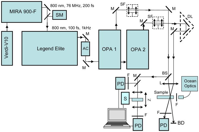
Figure 11.
Simplified schematic diagram of the experimental setup: SM - spectrometer; AC - optical autocorrelator; M - 100% reflection mirrors; BS - beam splitter; SF - space filters; DL - optical delay line with retro-reflector; PD -calibrated Si and/or InGaAs photodetectors; L - focusing lenses; F - set of neutral and/or interferometric filters; S -step motor; Sample – 1-mm flow quartz cuvette with investigated solutions; Z - Z-scan setup; BD - beam dump. Additional details are presented in the text.

