Abstract
Direct recordings were made of electrical signals emanating from the muscles in a rabbit’s residuum. The signals were transmitted via wires attached on one end to the muscles, and on the other to an external recording system. The cable was held in a titanium tube inside a pylon that had been transcutaneously implanted into the residuum’s bone. The tube was surrounded by porous titanium cladding to enhance its bond with the bone and with the skin of the residuum.
This study was the first known attempt to merge the technology of direct skeletal attachment of limb prostheses with the technology of neuromuscular control of prostheses, providing a safe and reliable passage of the electrical signal from the muscles inside the residuum to the outside recording system.
Index Terms: Bone, direct skeletal attachment, limb amputation, osseointegration, prosthetic rehabilitation, neurocontrol
I. INTRODUCTION
The work reported in this paper was dedicated to detecting and recording an electrical signal transmitted from the residuum transcutaneously.
Controlling limb prostheses with electrical signals from muscles or nerves [1] [2, 3] is a fast growing area in the field of functional electrical stimulation (FES) and neuroprosthetics [4–6]. The general principles of operating limb prostheses with electromyography (EMG) input were outlined about five decades ago, and were applied to hand prostheses [7, 8]. One of the first above knee prostheses to use EMG signals to control the knee locking mechanism was presented by Horn [9].
Todd Kuiken and colleagues developed the Targeted Muscle Reinnervation (TMR) technique to provide an intuitive prosthesis control [10]. With this technique, the amputated nerves in the residual limb are grafted to surgically denervated muscle [11, 12]. The re-innervated muscles serve as biological amplifiers of neural commands through the residual nerves. Surface electrodes record EMG signals from these muscles and use them to control physiologically related movements of the prosthesis.
There are several types of commercially available lower limb prostheses controlled by microprocessors; they are reviewed in [13]. However, none of them use efferent information from the user, like the myoelectric signal, as input for the control system. Attempts to use the EMG signal to directly and volitionally control a powered prosthetic knee were reported in [14, 15]. The transmission of EMG signals from the residual limb is a requirement for the control system’s safety and efficacy. However, collecting the EMG signal with surface electrodes may be a source of skin damage if the electrodes are positioned in the socket [13]. Additionally, there was a significant risk factor reported in accepting the EMG signal from the residuum muscles with surface electrodes [16], due to potential for the motion-induced artifacts which may result in falls.
First implantable electrodes penetrated by regenerating nerve fibers associated with leg movement were studied in unrestrained amphibians [17]. Edell recorded axonal electrical impulses in rabbits with electrodes running along microtubes manufactured with silicon microfabrication technology [18]. An array of microelectrodes were placed endoneurally within functional groups of axons. They were able to transduce available binary information from a multifunctional nerve. Since the precise location of the functional groups of axons cannot be predicted in a peripheral nerve, more contacts than the total number of functional groups were made to the nerve to ensure that all of the functional groups were represented.
The question of whether the controlling signal should be collected from the nerve or the muscle is debatable, and is outside the scope of this study. The authors would like to note that the practicality of both technologies depends not only on a workable connection of the electrode with the tissue generating the signal, but also on whether the signal can be passed safely outside the residuum.
For the latter, we suggest here a technique that merges the technology of microelectrodes with the technology of direct skeletal attachment of limb prostheses, which may utilize the advantages of the latter and increase its safety [19]. With this approach, a cable, fitted with microelectrodes, is safely held by and positioned in a specially designed device that is implanted directly into the residuum bone.
In the first step of the original direct skeletal attachment procedure [20], a fixture is implanted into the bone of the residuum, which is performed subcutaneously. After several months, when osseointegration of the fixture and hosting bone is complete, a component called the abutment is inserted into the fixture transcutaneously. The abutment is designed such that a limb prosthesis can then be attached to it.
An alternative to the original two-step procedure of direct skeletal attachment is a one-step technique [21–24], which we used in the current study. For the one-step transcutaneous implantation we used device called a pylon, one end of which is implanted in the bone and the other is positioned outside of the residuum for connection with the limb prosthesis.
The first verification of this methodology is reported in this paper. The electrical signal, recorded directly from the m. gastrocnemius in a rabbit’s residuum, was transmitted with a cable and recorded outside of the animal’s body. The cable was held in a titanium tube inside a pylon that was implanted into the residuum’s bone. The tube was surrounded by porous titanium cladding to enhance its bond with the bone and with the skin of the residuum.
II. METHODS
Development of composite porous pylon with the axial canal
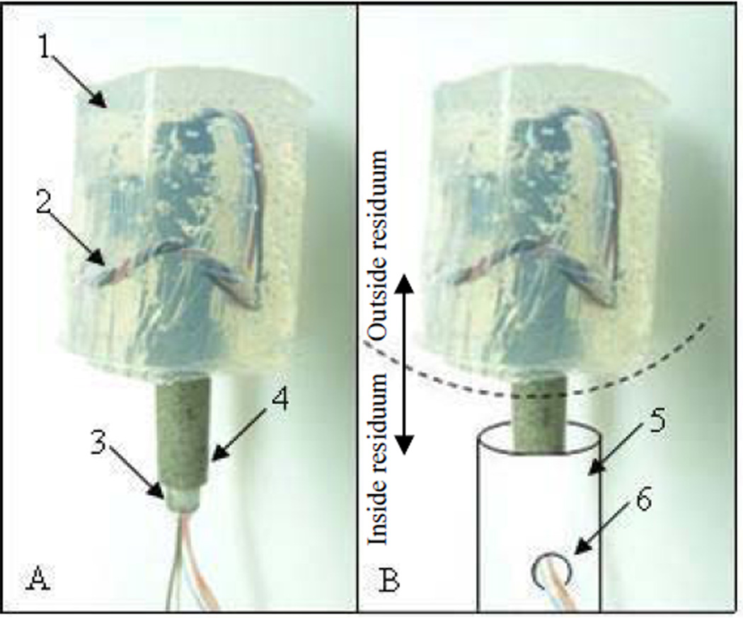
The composite porous pylon with peripheral nerve interface (PNI) was developed by Poly-Orth International, Sharon, MA. The design of the PNI pylon consisted of a tubular insert surrounded by a porous cladding [22, 25]. with the characteristics allowing for osseointegration to occur and and the safe seal of the surrounding skin [25, 26]. The tubular insert with an outside diameter of 3 mm, and inside diameter of 2 mm (SmallParts, Seattle, WA) was sintered (ADMA Products Group, Hudson, OH) with powders in cylindrical boron nitride molds (Payne Engineering & Fab. Co., Canton, MA), each 5 mm in diameter. The titanium alloy Ti6Al4V ELI was used as the material for the tubular insert and for the powders. The pylon SBIP-PNI is shown in Fig. 1-A with silicon shield (1) for the wire electrodes (2) passing through the tube (3) surrounded by the porous cladding (4). The placement of the pylon in the residuum is explained in Fig. 1-B. The portion of the implant below the dashed arc is positioned in the bone of the residuum, schematically drawn as a cylinder (5). The electrodes are passed through hole (6) out of the medullary canal to be implanted into the muscle or nerve. The portion of the pylon above the arc is outside the residuum.
Figure 1.
A – the implant SBIP-PNI with silicon shield 1 for wire electrodes 2 passing through the tube 3 surrounded by the porous cladding 4.
B – a portion of the implant below the dashed arc is to be positioned in the bone of the residuum, schematically drawn as a cylinder 5 with the hole 6 for releasing the electrodes from the medullary canal for implanting to the muscle or nerve; the portion above the dashed arc is to be outside of the residuum.
The high temperature sintering was conducted in a vacuum using titanium powders sieved to (−80+200) mesh. Samples were sintered for 4 hours at 1090°C, which was above the beta transus temperature of 996°C. Porosity of the sintered portion had an average range of 45 to 50%. The pore size was in the range of 30 µm - 200 µm.
Multi-stranded, Teflon-insulated, plated wires (~500um) were used as both interconnect and electrodes. The interface region of the wire and the pins in the connector were sealed prior to surgery with silicone to prevent any influx of body fluids (Fig. 1-A, 1).
Implantation Procedure
A white New Zealand rabbit was taken for the study that was conducted at the Pine Acres Research Facility, Norton, MA, following the IACUC2 approval of the protocol.
The implantation procedure replicated those developed for the cats in [22].
A temporary tourniquet was placed on the rabbit’s thigh prior to incision. The leg was then prepped using the usual sterile technique. A circumferential incision was made over the proximal tibia, roughly 4 cm distal to the proximal tibial articular surface. In making this incision, a posterior skin flap was designed to allow for tension-free closure. The muscles and tendons at this level were transected using monopolar cautery. Surgical dissection was undertaken to identify the anterior and posterior neurovascular bundles, which were then ligated and transected. Soft tissue attachments were stripped off the tibia for 1 cm proximal to the anticipated level of the osteotomy. The tibial and fibular osteotomy was then made using an oscillating saw. The fibula was subsequently rongeured down 2 –3 cm proximal to the level of the tibial osteotomy. Any remaining soft tissue was transected using monopolar cautery, thereby completing the amputation.
The medullary canal of the tibia was broached using a curette. The canal was then cleared of debris with a hand reamer. Once reaming was complete we used irrigation to help clear any remaining debris. A lateral 5mm burr hole for pullout of the electrodes was drilled in the bone wall as schematically shown in Fig. 1-B, 6. Reamer and irrigation were used to clean debris from the canal.
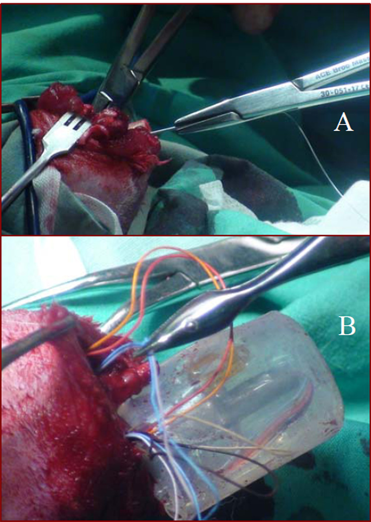
The sterilized SBIP-PNI pylon, 4 cm in length and with connected cuff leads, was inserted into the medullary canal of the tibia for a depth of approximately 1–2 cm. The depth of the implant was based on how tight the fit was in the canal. We kept inserting the pylon until we were able to achieve a good press fit in the canal. During insertion of the pylon into the medullary canal, the cuff leads attached to the pin were gently pulled through the hole on the lateral side of the bone to make room for the pylon inside the bone. This was done by inserting a needle connected to suture through the burr hole into the canal. This needle was then pulled out from the amputated end of the canal (Fig. 2-A). Care was taken to make sure the suture was not pulled all the way through the burr hole. The needle was removed and the suture that remained was tied to the electrodes. The other end of the suture was then used to guide the electrodes through the burr hole (Fig. 2-B).
Figure 2.
A - insertion of a suture through the bone canal and the hole in the bone wall;
B – wire electrodes guided through the burr hole.
The implant was then inserted into the tibial medullary canal using a mallet. The tibia was then cerclaged for added stability. Prior to closure, the fat and subcutaneous tissue of the posterior skin flap were sharply excised to the level of the dermis.
In order to test the viability of signals from the remnants of cut muscles after amputation, the rabbits were implanted with bipolar muscle electrodes. The electrodes were fitted onto the proximal residuum of the cut m. medial gastrocnemius and m. extensor digitorum longus. These muscles have extensor- and flexor-related activity during locomotion and can be used in the future to control a powered prosthesis.
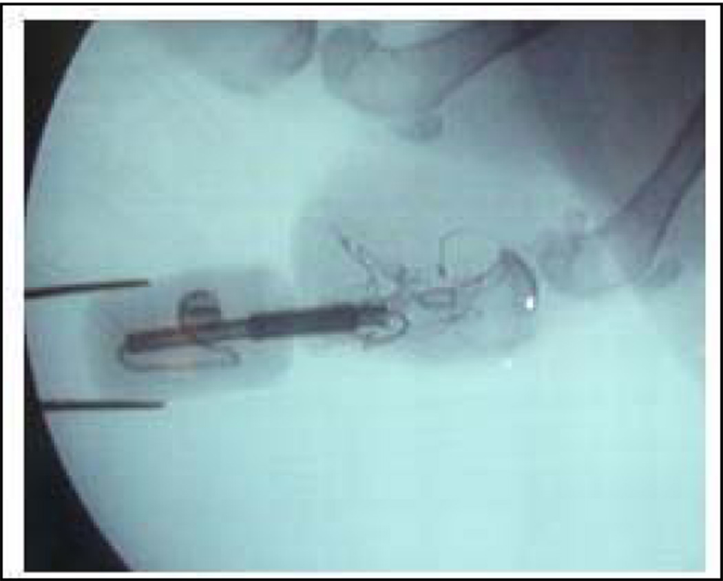
The wound was copiously irrigated with normal saline and the gastrocnemius muscle was debulked as needed prior to closure to ensure a tension free suture line. A small stab incision was made in the flap using a 10 blade for the implant to exit. The wound was then closed with a 4-0 nylon suture so that the dermal portion of the posterior skin flap directly overlaid and made contact with the distal end of the tibia. Prior to closure special care was taken to bring the skin flap in contact with the porous portion of the implant. At the end of the procedure, sterile gauze was placed on the wound and Coban wrap was applied. The position of the implant was confirmed after the procedure using fluoroscopy (Fig. 3).
Figure 3.
X-ray of the residuum with implanted pylon SBIP-PNI.
Signal Measurement and Processing
The composite porous pylons (SBIP-PNI) were modified to accept an Omnetics Nano series connector as well as to provide a resilient prosthesis for the animal by casting a silicone cylinder over the protruding portion of the bone interface, as shown in Fig. 1. The connector leads were passed through the lumen of the bone interface, and electrodes were created by simply stripping the insulation for 5mm, bending 180° and electroplating silver over the exposed wire. Two pairs of electrodes were joined with 15mm center to center spacing using Nusil MED4-4220. An additional set of electrodes were included to provide reference potential for the instrumentation amplifier input stage. The amplifier used in these experiments was not designed to be particularly small.
The connector was protected from the animal by containment within a pocket in the silicone prosthesis. During surgery, electrodes were pulled through the lumen of the tibia and exited a small 5 mm burr hole. The reference electrodes were positioned in the subcutaneous space while the pairs of recording electrodes were embedded within the residual musculature and sutured in place.
Three weeks after the surgery, the rabbit was sedated with Valium prior to the recording session. Once sedated, amplifiers were taped to the pylon and plugged into the connector.
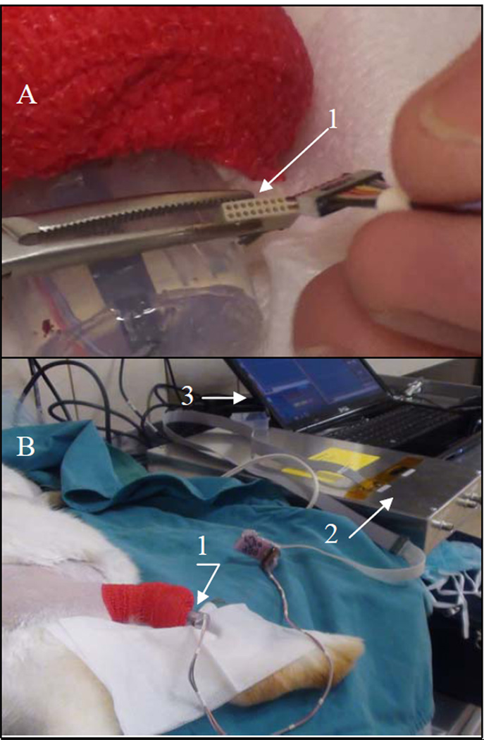
The sedated animal was rocked back and forth to elicit the "righting reflex" where the animal resists the torsion by activation of extensors of the ankle. At the time of recording, the connector was retrieved from the protective silicone pocket (Fig. 4-A), and the instrumentation was attached (Fig. 4-B). Recordings were accomplished using standard instrumentation amplifier techniques with gain of 1000× and bandwidth of 17–500Hz and sampled at 4kHz.
Figure 4.
Setting of the signal acquisition and recording: A - the connector 1 that leads to the implanted electrodes retrieved from the protective silicon pocket for attachment to the amplifier;
B – outer part 1 of the implanted pylon SBIP-PNI tethered to the data acquisition unit 2 and the computer 3.
III. RESULTS
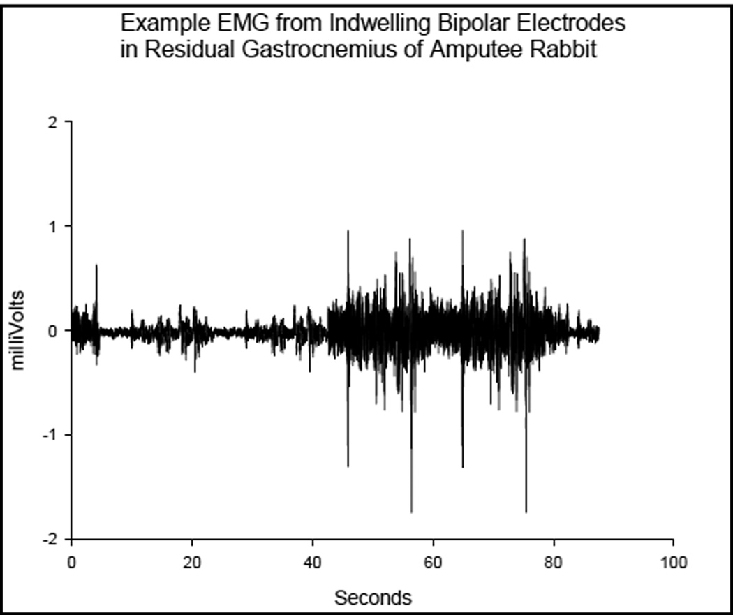
The example waveform shown in Fig. 5 was from the differential pair of electrodes embedded within the residual gastrocnemius muscle. Activity was elicited by gently rocking the otherwise unrestrained animal to evoke a righting reflex. The smaller bursts were from tensing of the muscles while the larger bursts were from the animal moving overtly.
Figure 5.
Example EMG collected and recorded outside of the rabbit from indwelling bipolar electrodes in residual m. Gastrocnemius
Movement of the prosthesis relative to the bone caused lead breakage so only one muscle could be accessed once the healing process had completed. However, the principal was demonstrated by recording quality EMG, shown in Fig. 5, which was recorded from that muscle prior to the conclusion of the experiment.
IV. DISCUSSION
The current study was the first to explore how direct skeletal attachment can be incorporated in neurocontrol of limb prostheses. The authors suggest that while both technologies are in a state of development with limited clinical applications, their union might be productive.
Direct differential recording of EMG from residual muscles and/or muscles re-programmed through targeted muscle re-innervation results in an efficient, robust system for precision EMG control of prostheses. The direct acquisition and recording technique eliminates many of the usual interferences associated with Surface EMG (SEMG) techniques now in use, and avoids the need for expensive implantable electronics. Rather, existing myoelectric prosthesis electronics are fully sufficient for recording from indwelling EMG electrodes, and will not suffer in performance from changes in fat, hydration of the skin, sweat, motion of the electrodes relative to the skin, or motion of electrodes relative to the underlying target muscle.
For direct bone interface mounted prostheses, direct wiring of the residual muscles of interest could be incorporated to provide access to all residual muscles, not just the superficial, large muscles accessed by SEMG techniques.
Further studies are needed to assess the effects on osseointegration and risks of infection due to the hole in the bone wall that wires pass through. The number of electrodes to be implanted depends entirely on the number of residual muscles that are of interest for prosthetic control. It would be advantageous to implant several electrodes over each muscle in order to more comprehensively measure muscular activity.
V. CONCLUSIONS
A stable transmission of the signal from the muscles of the residuum to the outside on the body was achieved.
A merge of the technology of direct skeletal attachment with neurocontrol over prosthetic performance will be an important advancement in prosthetic rehabilitation.
This study was the first known attempt to merge the technology of direct skeletal attachment of limb prostheses with the technology of neuromuscular control of prostheses, providing a safe and reliable passage of the electrical signal from the inside the residuum to the outside recording system.
ACKNOWLEDGMENTS
This work was supported in part by the National Institute of Health (grant 5R44HD5749203).
This work was supported in part by the NIH Award Number R44HD057492 from the Eunice Kennedy Shriver National Institute of Child Health & Human Development
Footnotes
Institutional Animal Care and Use Committee
Contributor Information
M. Pitkin, Department of Physical Medicine and Rehabilitation, Tufts University School of Medicine, Boston, MA 02111 (phone: 781-784-4434; mpitkin@tuftsmedicalcenter.org).
C. Cassidy, Department of Orthopaedics, Tufts University School of Medicine, Boston, MA 02111 (ccassidy@tuftsmedicalcenter.org).
R. Muppavarapu, Department of Orthopaedics, Tufts University School of Medicine, Boston, MA 02111 (RMuppavarapu@tuftsmedicalcenter.org).
David Edell, Inner Sea Technology, Bedford, MA 01730 (djedell@innersea.com)..
REFERENCES
- 1.Dhillon GS, Lawrence SM, Hutchinson DT, Horch KW. Residual function in peripheral nerve stumps of amputees: implications for neural control of artificial limbs. The Journal of hand surgery. 2004;29(4):605–615. doi: 10.1016/j.jhsa.2004.02.006. [DOI] [PubMed] [Google Scholar]
- 2.Jia X, Koenig MA, Zhang X, Zhang J, Chen T, Chen Z. Residual motor signal in long-term human severed peripheral nerves and feasibility of neural signal-controlled artificial limb. The Journal of hand surgery. 2007;32(5):657–666. doi: 10.1016/j.jhsa.2007.02.021. [DOI] [PubMed] [Google Scholar]
- 3.Rossini PM, Micera S, Benvenuto A, Carpaneto J, Cavallo G, Citi L, Cipriani C, Denaro L, Denaro V, Di Pino G. Double nerve intraneural interface implant on a human amputee for robotic hand control. Clinical neurophysiology. 2010;121(5):777–783. doi: 10.1016/j.clinph.2010.01.001. [DOI] [PubMed] [Google Scholar]
- 4.Navarro X, Krueger TB, Lago N, Micera S, Stieglitz T, Dario P. A critical review of interfaces with the peripheral nervous system for the control of neuroprostheses and hybrid bionic systems. Journal of the Peripheral Nervous System. 2005;10(3):229–258. doi: 10.1111/j.1085-9489.2005.10303.x. [DOI] [PubMed] [Google Scholar]
- 5.Stieglitz T, Schuetter M, Koch KP. Implantable biomedical microsystems for neural prostheses. Engineering in Medicine and Biology Magazine, IEEE. 2005;24(5):58–65. doi: 10.1109/memb.2005.1511501. [DOI] [PubMed] [Google Scholar]
- 6.Aravamudhan S, Bellamkonda RV. Towards a Convergence of Regenerative Medicine, Rehabilitation and Neuroprosthetics. Journal of Neurotrauma. 2011;28:1–20. doi: 10.1089/neu.2010.1542. [DOI] [PubMed] [Google Scholar]
- 7.Battye CK, Nightingale A, Whillis J. The use of myo-electric currents in the operation of prostheses. Journal of Bone and Joint Surgery-British Volume. 1955;37(3):506. doi: 10.1302/0301-620X.37B3.506. [DOI] [PubMed] [Google Scholar]
- 8.Kobrinsky A, Gurfinkel V, Breido M, Sysin A, Tsetlin M, Yakobson Y. Prototype of a mechanical actuator for the prosthesis controlled by the muscles biosignals. VI Scientific Session, CNIIP, Moscow. 1958:153–153. [Google Scholar]
- 9.Horn GW. Electro-control: am EMG-controlled A/K prosthesis. Medical and Biological Engineering and Computing. 1972;10(1):61–73. doi: 10.1007/BF02474569. [DOI] [PubMed] [Google Scholar]
- 10.Kuiken TA, Miller LA, Lipschutz RD, Lock BA, Stubblefield K, Marasco PD, Zhou P, Dumanian GA. Targeted reinnervation for enhanced prosthetic arm function in a woman with a proximal amputation: a case study. Lancet. 2007;369(9559):371–380. doi: 10.1016/S0140-6736(07)60193-7. [DOI] [PubMed] [Google Scholar]
- 11.Stubblefield KA, Miller LA, Lipschutz RD, Kuiken TA. Occupational therapy protocol for amputees with targeted muscle reinnervation. J Rehabil Res Dev. 2009;46(4):481–488. doi: 10.1682/jrrd.2008.10.0138. [DOI] [PMC free article] [PubMed] [Google Scholar]
- 12.Miller LA, Lipschutz RD, Stubblefield KA, Lock BA, Huang H, Williams TW, 3rd, Weir RF, Kuiken TA. Control of a six degree of freedom prosthetic arm after targeted muscle reinnervation surgery. Arch Phys Med Rehabil. 2008;89(11):2057–2065. doi: 10.1016/j.apmr.2008.05.016. [DOI] [PMC free article] [PubMed] [Google Scholar]
- 13.Martin J, Pollock A, Hettinger J. Microprocessor Lower Limb Prosthetics: Review of Current State of the Art. JPO: Journal of Prosthetics and Orthotics. 2010;22(3):183. [Google Scholar]
- 14.Ha KH, Varol HA, Goldfarb M. Volitional control of a prosthetic knee using surface electromyography. IEEE Trans Biomed Eng. 2011;58(1):144–151. doi: 10.1109/TBME.2010.2070840. [DOI] [PubMed] [Google Scholar]
- 15.Sup F, Varol HA, Mitchell J, Withrow TJ, Goldfarb M. Preliminary Evaluations of a Self-Contained Anthropomorphic Transfemoral Prosthesis. IEEE ASME Trans Mechatron. 2009;14(6):667–676. doi: 10.1109/TMECH.2009.2032688. [DOI] [PMC free article] [PubMed] [Google Scholar]
- 16.Pantall A, Durham S, Ewins D. Surface electromyographic activity of five residual limb muscles recorded during isometric contraction in transfemoral amputees with osseointegrated prostheses. Clin Biomech (Bristol, Avon) 2011;26(7):760–765. doi: 10.1016/j.clinbiomech.2011.03.008. [DOI] [PubMed] [Google Scholar]
- 17.Mannard A, Stein RB, Charles D. Regeneration electrode units: implants for recording from single peripheral nerve fibers in freely moving animals. Science. 1974;183(124):547–549. doi: 10.1126/science.183.4124.547. [DOI] [PubMed] [Google Scholar]
- 18.Edell DJ. A peripheral nerve information transducer for amputees: long-term multichannel recordings from rabbit peripheral nerves. IEEE Trans Biomed Eng. 1986;33(2):203–214. doi: 10.1109/TBME.1986.325892. [DOI] [PubMed] [Google Scholar]
- 19.Frossard LA, Tranberg R, Haggstrom E, Pearcy M, Brånemark R. Load on osseointegrated fixation of a transfemoral amputee during a fall: loading, descent, impact and recovery analysis. Prosthetics and orthotics international. 2010;34(1):85. doi: 10.3109/03093640903585024. [DOI] [PubMed] [Google Scholar]
- 20.Branemark R, Branemark PI, Rydevik B, Myers RR. Osseointegration in skeletal reconstruction and rehabilitation: a review. J Rehabil Res Dev. 2001;38(2):175–181. [PubMed] [Google Scholar]
- 21.Pitkin M. On the way to total integration of prosthetic pylon with residuum. J Rehabil Res Dev. 2009;46(3):345–360. doi: 10.1682/jrrd.2008.08.0112. [DOI] [PMC free article] [PubMed] [Google Scholar]
- 22.Pitkin M, Raykhtsaum G, Pilling J, Shukeylo Y, Moxson V, Duz V, Lewandowski J, Connolly R, Kistenberg RS, Dalton JF, Prilutsky B, Jacobson S. Mathematical modeling and mechanical and histopathological testing of porous prosthetic pylon for direct skeletal attachment. J Rehabil Res Dev. 2009;46(3):315–330. doi: 10.1682/jrrd.2008.09.0123. [DOI] [PMC free article] [PubMed] [Google Scholar]
- 23.Shelton TJ, Peter Beck J, Bloebaum RD, Bachus KN. Percutaneous osseointegrated prostheses for amputees: Limb compensation in a 12-month ovine model. Journal of Biomechanics. 2011 doi: 10.1016/j.jbiomech.2011.08.020. [DOI] [PMC free article] [PubMed] [Google Scholar]
- 24.Pendegrass CJ, Goodship AE, Price JS, Blunn GW. Nature's answer to breaching the skin barrier: an innovative development for amputees. Journal of Anatomy. 2006;209(1):59–67. doi: 10.1111/j.1469-7580.2006.00595.x. [DOI] [PMC free article] [PubMed] [Google Scholar]
- 25.Pitkin M, Raykhtsaum G. Skin Integrated Device. No.11/233. US Patent Application. 2005;233
- 26.Pitkin M, Raykhtsaum G, Galibin OV, Protasov MV, Chihovskaya JV, Belyaeva IG. Skin and bone integrated prosthetic pylon: a pilot animal study. J Rehabil Res Dev. 2006;43(4):573–580. doi: 10.1682/jrrd.2005.05.0160. [DOI] [PMC free article] [PubMed] [Google Scholar]


