Abstract
This article presents results of the further development and testing of the “skin and bone integrated pylon” (SBIP-1) for percutaneous (through skin) connection of the residual bone with an external limb prosthesis. We investigated a composite structure (called the SBIP-2) made of titanium particles and fine wires using mathematical modeling and mechanical testing. Results showed that the strength of the pylon was comparable with that of anatomical bone. In vitro and in vivo animal studies on 30 rats showed that the reinforcement of the composite pylon did not compromise its previously shown capacity for inviting skin and bone cell ingrowth through the device. These findings provide evidence for the safe and reliable long-term percutaneous transfer of vital and therapeutic substances, signals, and necessary forces and moments from a prosthetic device to the body.
Keywords: amputation, bone, cell ingrowth, mathematical modeling, mechanical testing, prosthesis, pylon, rehabilitation, residuum, skin, titanium
INTRODUCTION
Prosthetic rehabilitation after limb amputation is a multifaceted problem. Forces and moments are transferred from the prosthesis through the interface of the socket with the tissues and skin of the residuum, often resulting in discomfort, pain, and secondary trauma [1]. To eliminate the negative outcomes of the socket-type attachment, Dr. Per-Ingvar Brånemark and his colleagues introduced direct attachment of prostheses to the residuum [2–3]. An abutment is implanted in the bone of the residuum, passing through the skin and allowing the prosthesis to be attached to the residuum. A serious concern is that the abutment-skin interface is vulnerable to infection [4]. Studies have tested abutments made from different materials with various circumferential components; these studies aimed to promote and increase the binding junction with the skin [5]. However, porous circumferential components—advantageous in the bone-device interface—were found to be possible sources of infection in the skin-device zone [6]. Attempts to optimize the roughness of the abutment for a reliable and infection-free skin-device interface were also unsuccessful [7]. Current clinical studies use abutments with smooth surfaces, which could potentially form a layer of pus between the skin and the titanium [8].
Promising results toward achieving a barrier against infection were reported with use of a solid bar with a flexible mesh collar and holes at the subcutaneous perimeter [9–10], as well as use of a collar made by attachment of a stainless steel spring or nylon hooks [11]. Pendegrass and colleagues tested a solid core with a porous flange positioned in the dermal tissues immediately below the epithelium [12–13]. Reduced mobility of skin in the plane parallel to the mesh collar or porous flange was reported. However, cells did not penetrate perpendicular to the wall of the central core; thus, the attachment of skin to the solid core was fragile. Moreover, devices with connecting collars or flanges are sensitive to their positioning relative to derma and subcutaneous tissues and may not tolerate junction shifting when the distance from the bone to the skin-binding junction changes [11].
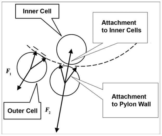
Our approach is distinctive because the implanted pylon is porous throughout [14]. This approach promises several advantages. First, by removing the circumferential collars and flanges, we can reduce the affected area of skin and tissues outside the pylon. Second, because the pylon is porous along the entire longitudinal axis, repositioning the skin does not have negative consequences, as it did in the prior model. Third, the resistance to detachment increases because of the natural bond of the cells outside the pylon to the cells inside the pylon. The latter is illustrated in Figure 1, in which F1 and F2 are the minimal forces needed for detachment of a skin cell from the pylon with the traditional “cell-to-wall” and the new “cell-to-wall-to-inner cell” attachments, respectively. If a natural bond is permitted between the cells outside and inside the pylon through a pore in the pylon wall, an additional “cell-to-cell” attachment (adhesion) force contributes to the resistance to the cell’s detachment, resulting in F2 being greater than F1.
Figure 1.
Minimal force needed for detachment of skin cell from pylon. F1 = “cell-to-wall” detachment (prior design), F2 = “cell-to-wall-to-inner cell” detachment (current design).
In our preliminary in vivo studies, rats with a porous skin and bone implanted pylon 1 (SBIP-1) [15] showed (1) no signs of inflammation compared with control rats with a solid pylon and (2) clear integration of the pylon with the surrounding skin. Twenty-eight days after the operation, the implants were removed from the animals and investigated with electronic microscopy. Solid implants did not have visible signs of surrounding tissues on their surfaces, while a combination of cells and fibers, including erythrocytes and lymphoid cells, were found inside the SBIP-1 in the area of contact with the bone and surrounding skin. In the tissues surrounding the implants at the skin level and under the skin, no signs of inflammation were seen in the experimental SBIP-1 group, while some abscess indicators were seen in the control group. We concluded that the experimental SBIP-1 provided an inviting environment for the surrounding tissues [15].
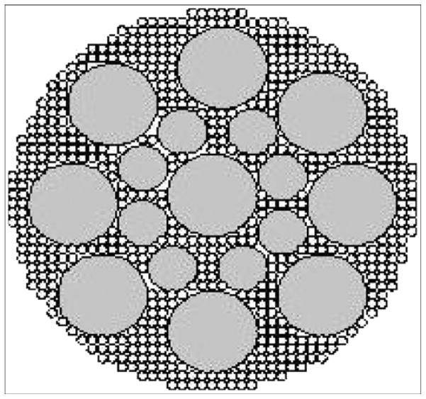
Our next step was to strengthen the SBIP-1 sufficiently to withstand the loads associated with gait with the leg prosthesis while preserving its inviting environment for skin ingrowth. The current article presents the theoretical estimate of the required pylon strength and a mathematical model for predicting the mechanical properties of the composite porous SBIP-2, which is made of sintered particles and enforced with fine wires (Figure 2). The mechanical tests showed that the strength of the SBIP-2 is similar to that of anatomical bone [16]. The animal study with 30 rats showed that the SBIP-2 integrated with bone and skin without inflammation but the solid pylons led to infected skin-device interfaces. The in vitro study with human skin cells showed that their ingrowth into the SBIP-2 pretreated with human fibrin was similar to that of the untreated SBIP-2.
Figure 2.
Cross section of porous pylon with enforcing wires. Pitkin M, Raykhtsaum G, inventors. Skin integrated device. United States patent US 20070071788. 2005 (in process).
METHODS
Development of Composite Porous Pylon
Strength Requirements
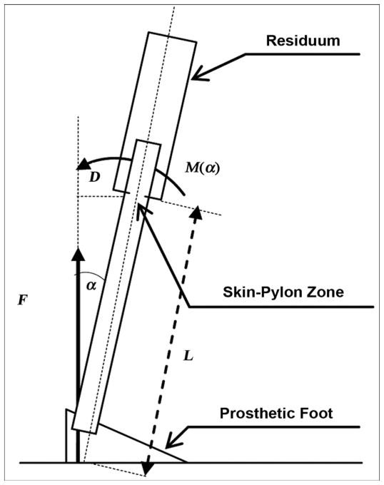
Consider a model for a static load on the implanted pylon (Figure 3) and calculate the moment M(α) applied from the ground reaction force F relative to the skin-pylon zone. That zone is the most vulnerable in terms of durability. The moment M(α) can be calculated as
Figure 3.
Estimate of moment M(α) relative to skin-pylon zone, where α is angle of dorsiflexion. D = lever arm of force F relative to point of skin-pylon connection, L = length of exposed part of pylon.
| (1) |
where L is the length of the exposed part of the pylon inclined at angle α and F is the vertical component of the ground reaction force.
The stress P that is caused by moment M at the skin-pylon zone point may be calculated as
| (2) |
where D is the diameter of the pylon [17].
We calculated stress values using Equation 2 for angle α = 5°, 10°, and 15°. The corresponding values of M(α) were calculated with Equation 1 for L = 0.4 m and F = 981 N (100 kgf). The stress dissipates when the diameter of the pylon increases. The minimum requirement for the material strength is determined by
| (3) |
where Y is the flexural yield strength of the whole pylon. With n being the strength safety factor, the material strength requirement becomes
| (4) |
where n = 1, 2, 3….
In the gait of a person with an amputation, the prosthetic joint amplitude is typically lower than in the gait of a nondisabled person [18–19]. Therefore, 15° of dorsiflexion is a reasonable target [20]. We did not consider the moment from the horizontal component of the ground reaction force because it would only decrease the value of M(α) as calculated in Equation 1, but we used the conservative approach to estimate the needed stress for the porous pylon. The rational for this approach is that during the first half of the stance period, the horizontal ground reaction force is negative as it acts in the aft direction. During the second half of the stance period, the horizontal ground reaction force is positive as it acts in the fore direction. Thus, the moment generated by the horizontal component of the ground reaction force will always have the opposite sign as the moment generated by the vertical component F (Figure 3).
For clinical application in the skin-pylon zone, the diameter of the pylon should not exceed 2 cm. Larger pylon size may increase the risk associated with implantation of the device into the patient’s residuum by increasing the area that is not covered by the surrounding skin. Therefore, the material should show a yield stress value of at least 200 MPa and fatigue strength of about 130 MPa.
Manufacturing and Mechanical Testing
Following our preliminary in vitro [21] and in vivo [15] studies, we found that a combined pore size of ~50 m and porosity of >35 percent were appropriate for skin and bone ingrowth. However, the initial samples of sintered spherical particles were not sufficiently strong to be considered for further in vivo studies. We subsequently established the goal of reaching a pylon strength of no less than 157 MPa, which is typical for anatomical bone [16]. To increase strength, we developed a technology for producing composite rods composed of several single fine wires sintered with a mixture of spherical particles and a titanium sponge (Figure 2).
The 3 mm-diameter and 50 mm-long rod samples with and without reinforcing wires were prepared and sintered in vacuum at three temperatures: 1,316 °C (2,400 °F), 1,371 °C (2,500 °F), and 1,427 °C (2,600°F). The porosity φ (%) was calculated as
| (5) |
where Wp is the weight of the sintered rod sample and Ws is the weight of a solid titanium rod of the same size. We subjected the samples to a three-point bend test with a 19 mm-span of length L using an Instron tensile machine (Model 1123; Instron, Norwood, Massachusetts) (Figure 4). Test results are presented in the “Results” section.
Figure 4.
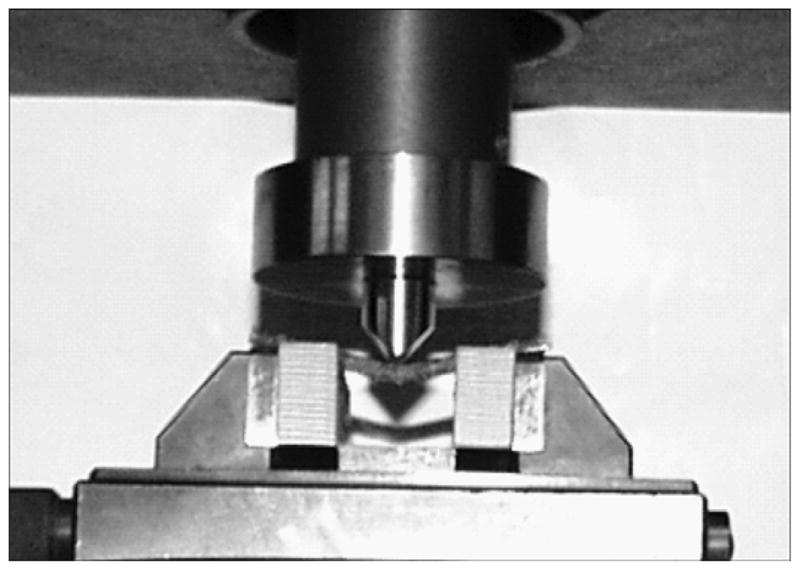
Bend test setup. Instron tensile machine (Model 1123; Instron, Norwood, Massachusetts).
Modeling Mechanical Properties
The principal mechanical properties of interest in the titanium composite pylon are its resistance to failure in bending under static or cyclical loading together with its tensile and compressive strengths. The pylon can be envisioned as a laminated structure [22], shown in Figure 5. When sectioned, this structure has a core that can be solid, porous, or hollow; a region of solid wire fibers embedded in a matrix of the same porous solid; and an outer skin of the porous solid. The mechanical properties of the structure, in particular its tensile and flexural stiffness, its strength in bending, and its conventional tensile and compressive strengths can be estimated as follows. The tensile modulus parallel to the axis of the cylinder is the sum of the tensile moduli of each concentric ring multiplied by the area fraction of the cross section occupied by that ring:
| (6) |
where Ef is the elastic modulus of the fibers, ai is the cross-sectional area (a) of the ith ring, ri is the radius (r) of the ith ring, and Ei its elastic modulus (r0 = 0). The flexural modulus can be determined by calculation of the forces and moments applied to the cylindrical rod in terms of a sum of forces in each ring. The total force Fx and moment Mx acting along the length of the beam are
Figure 5.
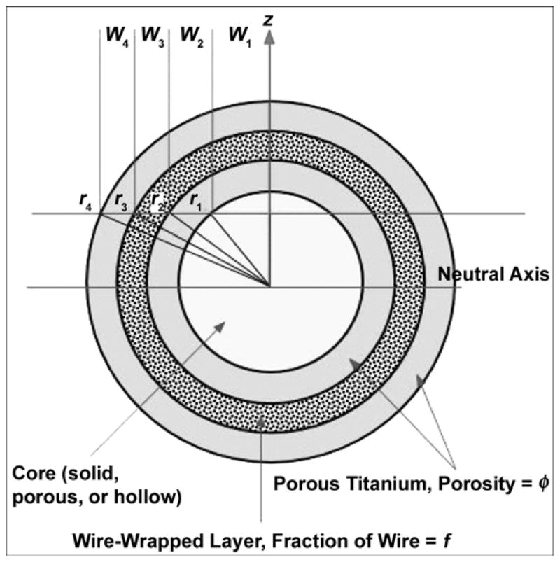
Geometry used to model mechanical behavior of composite rods. r = radius, w = width, z = height.
| (7) |
where σx is the stress acting along the cylinder axis and w(z) is the width of the cylinder at a height z above or below the centerline. At any height z above the center-line, the width of the cylinder is made up of contributions from the width of each ring segment, there being two segments per slice, where
| (8) |
Hence,
| (9) |
where Ei is the elastic modulus of the i’th ring and εx is the axial strain. Given that the axial strain at any height above the centerline depends on both the uniform tensile strain and the curvature κx,
| (10) |
reverting to conventional laminate/tensor notation:
| (11) |
In a cylindrical laminate, where the structure and elastic properties of each ring are symmetric about the center-line, the A, B, and D equalities reduce to
| (12) |
Since A is a product of tensile stiffness and cross-sectional area, while D is the product of flexural stiffness and moment of inertia I, then
| (13) |
and the tensile stiffness ET is identical to that calculated earlier. The elastic properties of each ring can be described in terms of the elastic modulus of titanium ETi, the porosity φ, and the volume fraction of wires f. For the current configuration of a porous core surrounded by a wire-reinforced layer and porous skin,
| (14) |
When the porosity is zero, the elastic properties reduce to those of solid titanium.
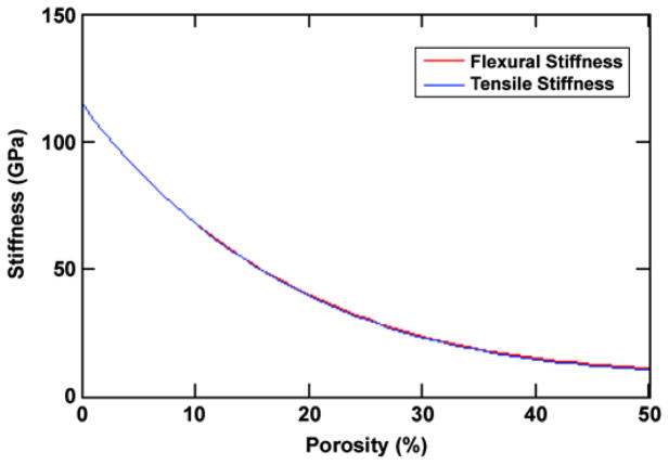
The stiffness of the current geometry (Figure 5) is shown in Figure 6 as a function of porosity for three wires with a 0.466 mm diameter around a 1.67 mm-diameter core (f = 16%). The bending stiffness of the compacts was measured from the slope of the load deflection plots (Figure 4),
Figure 6.
Calculated variation of stiffness with porosity for three-wire geometry. Pitkin M, Raykhtsaum G, inventors. Skin integrated device. United States patent US 20070071788. 2005 (in process).
| (15) |
and found to be 2 GPa. Traditionally, the elastic stiffness of a porous structure is represented by E = Es (1 − φ)2, where Es is the elastic modulus of the solid and φ the volume fraction of porosity in the porous solid. Given the measured stiffness of the sintered compacts, an exponent of 5.5 would be more appropriate. The bending stiffness of the three wire samples can be modeled by assumption of an annular homogeneous layer with a thickness equal to the wires (0.467 mm) and an inside diameter of 1.67 mm. The stiffness of the annular material is equal to that of material comprising solid titanium wires in a porous titanium matrix calculated as
| (16) |
where f is the volume fraction of solid titanium and φ is the porosity of the titanium matrix. The volume fraction in this case is simply the ratio of the cross-sectional area of the three wires to the cross-sectional area of the annulus, i.e., 16 percent. Using this value, together with the measured porosity, we calculate the bending stiffness E (Equation 15) of the three-wire reinforced sample to be 11.1 GPa. This result compares favorably with the measured bending stiffness of 7.9 GPa (Figure 6); any discrepancies most likely arise from the nonuniform distribution of the wires in the manufactured sample. The tensile strength of the structure is determined by the stress required to extend the composite structure parallel to the core until a critical strain is exceeded, namely the lesser of the elastic strain to yield and/or fracture of the wires, core, or of the porous matrix. The critical strain ε for the wires and any solid core is
| (17) |
The critical strain for the porous solid depends on the volume fraction and size of the porosity. When the pores are small, the tensile strength scales linearly with the volume fraction of pores and the critical strain varies as
| (18) |
If the pores are large, they will act as local stress concentrations. The stress required to propagate a crack σ is given by
| (19) |
where KTi is the fracture toughness of titanium and a is the depth of a surface crack or pore.
In general, all titanium alloys used in biomedical devices (CP-Ti, Ti-6Al-4V, Ti-13Nb-13Zr, Ti-12Mo-6Zr-2Fe, Ti-5Al-2.5Fe, Ti-6Al-7V) have a fracture toughness value >50 MPam0.5, which yields a minimum tensile fracture strength of ~890 MPa for a 1 mm-long surface flaw. This stress is much higher than the tensile strength of the porous CP-Ti solid and is unlikely to cause failure in bending or tension. The compressive strength of the composite structure will be more complex to model since the behavior of compressed porous materials is far from linear [23]. Finally, the effects of diameter must be considered with regard to elastic collapse from buckling under compressive axial compressive loads.
The bending strength of the composite can be estimated if one knows the flexural rigidity of the beam and the elastic properties of each layer. From the imposed bending moment M at the point of failure, the stress at a point in the bending rod can be calculated based solely on its displacement from the plane of zero bending strain as
| (20) |
where EIeq is the flexural rigidity of the rod (the product of the bending stiffness of the rod and its moment of inertia), y is the vertical displacement from the center of the beam, and Ey is the elastic modulus of the material at that point.
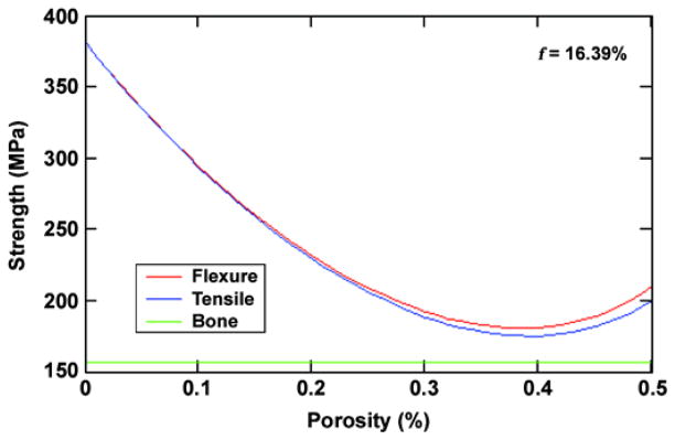
As the beam is bent, a stress gradient develops from center to surface. Given the flexural rigidity of the beam as a whole, the strain distribution across the beam section is defined for any imposed moment; given the strain at any point and the critical strain at any point in the section, the deflection and hence stress at which the beam fails can be determined. Failure will most likely occur on either the tensile side of the beam from cracking of the weaker porous surface layers or on the compression side because of collapse of the porous solid or elastic buckling of the thin wire composite layer. The flexural and tensile strength of the example cylinder are shown in Figure 7 as a function of porosity with an assumption of failure by tensile yielding and a design goal of 157 MPa for the bone strength.
Figure 7.
Calculated strength of three-wire composite structure compared with bone strength. Pitkin M, Raykhtsaum G, inventors. Skin integrated device. United States patent US 20070071788. 2005 (in process). f = fraction of wire.
In Vivo Animal Study
We investigated the healing process and the formation of an infection barrier on the porous titanium pylon-wound surface barrier.
Procedures
Adult male Wister rats (n = 30, 225–250 g; Ruppolovo Russian Academy of Medical Science, St. Petersburg, Russia) were handled in accordance with the National Institutes of Health Guidelines for the Care and Use of Laboratory Animals (publication 85-23, Rev 1985) and the American Veterinary Medical Association Panel on Euthanasia instructions. All procedures were performed in accordance with protocols approved by the ethics committee of the I. P. Pavlov State Medical University, St. Petersburg, Russia. We used two groups of animals: rats implanted with porous titanium pylons and rats implanted with solid titanium pylons. The rats were injected intraperitoneally with an anesthetic solution containing sodium pentobarbital (40 mg/mL Nembutal; Abbott Laboratories, Moscow, Russia) and diazepam (5 mg/mL; Roche Moscow Ltd, Moscow, Russia). Surgery was performed under sterile conditions. After putting the rats under general anesthesia and performing the transfemoral amputation, we implanted a pylon (3 mm in diameter and 40 mm in length) into the residual bone, stitched the residual skin around the pylon, and applied aseptic dressing. During the postoperative period, the animals had access to food and water. The main end point of comparison between the two groups was inflammation at the implantation site.
Experimental Group
We amputated one rear limb on the lower third of the thigh in 15 rats. The experimental porous titanium pylon (SBIP-2) was implanted into the residuum (Figure 8). A circular cut of the skin in the region of the upper third of the shin was made. Skin-fascia rag on the shin and on the lower and middle thirds of the thigh were then separated. Subsequently, the vascular bundle in the middle third of the thigh was stitched and tied up. The muscles of the thigh were circularly cut at the level of the lower third of the thigh. A capsule of the knee joint was cut and disarticulation was performed. The distal epiphysis of the femur bone was torn off with Lyston forceps. The marrow canal was trepanned and then bored out with cutters (diameters 1, 1.5, and 2.0 mm). The SBIP-2 was implanted into the marrow canal. The free end of the pylon was positioned at the center of the operative zone.
Figure 8.
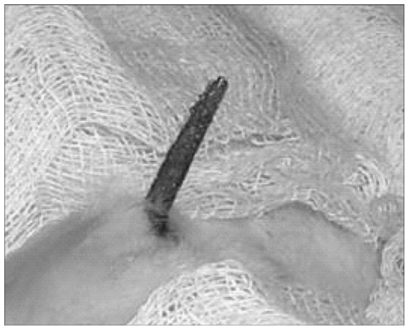
Implanted composite porous titanium pylon (skin and bone integrated pylon 2) on day 28 after operation.
Control Group
In the 15 control rats, we performed the amputation and implantation procedure as in the experimental group. The only difference was that the titanium pylon was not porous but solid.
Investigated Characteristics
To quantify the morphological differences between the experimental and control groups, we evaluated two characteristics: (1) intensity of neutrophil infiltration and (2) capillary development. We counted the number of cells and capillaries with a luminescent microscope (Lumam-IZ; LOMO PLC, St. Petersburg, Russia) at magnification ×320. For each of 30 slides (15 experimental and 15 control), we performed the count on 10 randomly selected fields that were within 500 μm of the implant surface.
Observation Periods
The observation periods were 14, 28, and 42 days postsurgery (five animals from each group at each observation period).
Morphological Investigation
We performed electronic scanning investigation of the porous and solid titanium implants (surface and cross section) using an electron scanning microscope (JEOL USA Inc, Peabody, Massachusetts) and morphological investigation of histological sections of surrounding tissues (hematoxylin-eosin and Van Gizon staining) using a light microscope (Lumam-01M; LOMO PLC, St. Petersburg, Russia).
In Vitro Human Skin-Cell Growth on Untreated and Pretreated Pylons
We investigated migration of human dermal fibroblasts within the SBIP-2 structure at the Institute of Cytology, Russian Academy of Sciences, St. Petersburg, Russia. Samples were prepared from the SBIP-2 titanium composite porous pylons. The size of samples fit a standard 24-well plate. Samples were autoclaved for 40 minutes with an extra 1 atm of pressure. Three groups of samples were formed. Group 1 included samples treated with type I collagen (Institute of Cytology, not commercially available), prepared from the tendon of rat tail (concentration = −0.1 mg/mL, temperature = 40 °C, duration of incubation = 24 h). Group 2 included samples treated with human fibrin (concentration = −2 mg/mL; temperature = 40 °C, duration of incubation = 24 h). Group 3 included untreated samples and served as the control. Three replicate wells were performed for each treatment. All samples were immersed in collagen gel with 105 human dermal fibroblast cells. The nutrient medium was Dulbecco’s modified Eagle medium (ICN, Strasbourg, France) with 10 percent fetal bovine serum (GIBCO, Carlsbad, California). During cultivation (14 days), the medium was changed four times. Observations were made on days 7 and 14.
RESULTS AND DISCUSSION
Mechanical Properties of Composite Porous Pylon
Results
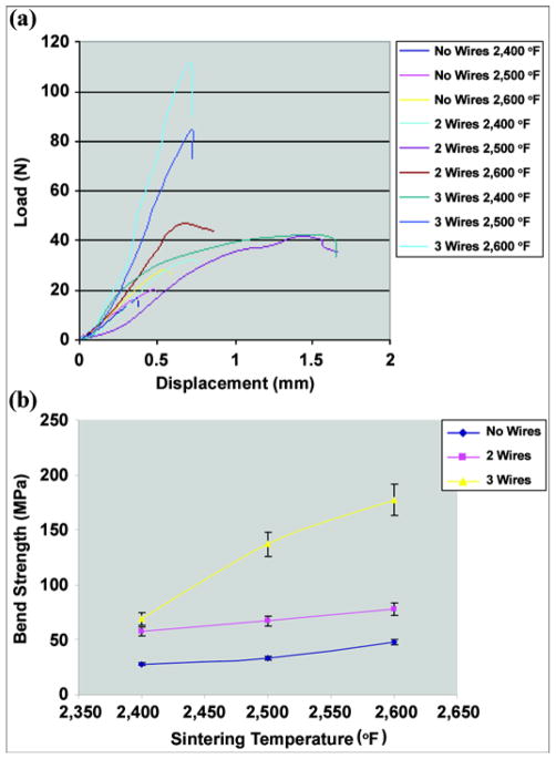
The typical load-displacement charts obtained at the bending test (Figure 4) are shown in Figure 9(a).
Figure 9.
(a) Typical load-displacement curves for composite samples without enforcing wires and with 2 and 3 wires sintered at different temperatures. (b) Bend strength of samples with no reinforcing wires and with 2 and 3 wires sintered at 2,400 °F, 2,500 °F, and 2,600 °F. Pitkin M, Raykhtsaum G, inventors. Skin integrated device. United States patent US 20070071788. 2005 (in process).
The bend strength σB was determined at the point of maximum load in the load-displacement curves (Figure 9(a)) with
| (21) |
where r is the radius of a rod.
The calculated average bend strength and standard deviation (SD) values are shown in Table 1. The sintering temperature effect on the bend strength of different composite structures is illustrated in Figure 9(b); error bars represent ±1 SD. The average bend strength of the sample with three reinforcing wires was as high as 177 MPa, exceeding the bone strength of 157 MPa (Figure 9(b)).
Table 1.
Effect of sintering temperature on bend strength of different composite structures. Data shown as mean ± standard deviation.
| Sintering Temperature (°F) | Strength (MPa)
|
||
|---|---|---|---|
| No Wires | 2 Wires | 3 Wires | |
| 2,400 | 28 ± 1 | 58 ± 1 | 69 ± 4 |
| 2,500 | 33 ± 1 | 67 ± 5 | 137 ± 11 |
| 2,600 | 48 ± 3 | 78 ± 6 | 177 ± 15 |
The results suggest that the bend strength of 200 MPa, which was estimated in our model (Figure 3), is achievable when smaller spherical particles are combined with a mesh sponge and reinforcing wires sintered at or above 2,600 °F.
Discussion
Although a composite porous structure strength close to that of the solid device is achievable, some limitations should be considered for a bone-integrated pylon. The solid implant is significantly stiffer than bone; therefore a mechanical mismatch is observed at the bone-implant interface [24]. The interfacial stress depends not only on the magnitude of the mechanical load but also on the difference in stiffness between implant and bone [25]. Therefore, the mechanical mismatch will increase interfacial stresses, affecting the bone tissue in the bone-implant contact zone [26].
In this case, a hollow tube is conceptually and functionally identical to a solid rod or a hollow tube (Figure 5) in which the tube wall is solid with interlinked porosity (sintered porous solid). The mathematical modeling that we performed is relevant whether the pylon is solid or porous. The model is based on the assumption that the material(s) used to construct the pylon has sufficient structural integrity to allow transmission of the bending stresses from one side to the other via shear coupling. The only difference is the value of the EI (flexural rigidity) of the structure, which depends on the materials (E) and shape (I).
Using the mathematical analysis developed previously, one can explore the effects of porosity, tube volume fraction, and overall diameter. The model shows that the elastic and strength properties are independent of the external diameter of the rod. Increasing the volume fraction of the tube from 0 to 60 percent increases the flexural stiffness by 16 percent and increases strength by 15 percent, while increasing porosity from 0 to 40 percent results in a 62 percent reduction in flexural stiffness and an almost 100 percent loss in strength. Varying the ratio of thicknesses of the porous and composite cylinders results in less than 5 percent variability in the overall mechanical properties at 25 percent porosity. Replacing the solid core with a tube with a 1.6 mm-thick wall reduces the flexural stiffness by only 6 percent but the tensile stiffness falls by over 40 percent, with the same reductions being observed in flexural and tensile strengths. Once the principal modes of failure of the implant device are identified and modeling of the compressive strengths of the design is completed, we will use the model to devise an internal pylon structure that will meet all the required mechanical specifications at a minimal diameter but still remain compatible with cell adhesion.
In Vivo Animal Experiment
Results
No rats in either group died. We noted no inflammation around the exit area of the pylon. On days 14, 28, and 42 after the operation, the implants were removed from the animals and investigated with electronic and light microscopy. The solid pylons were removed from the marrow canal without noticeable resistance. The porous titanium pylons were extracted with noticeable resistance, indicating their stronger interface with surrounding tissues.
Day 14 After Operation
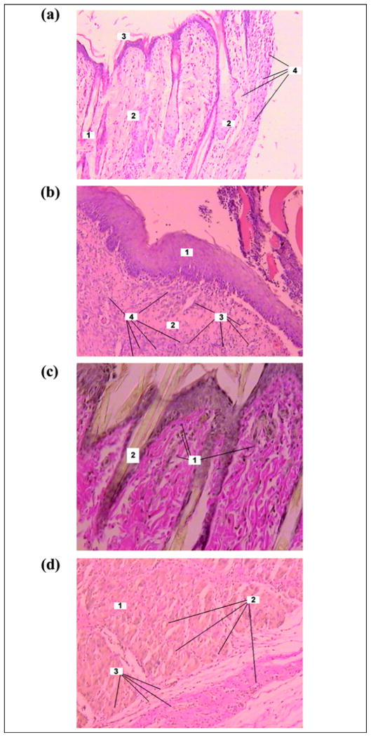
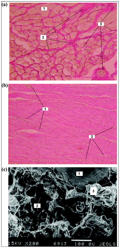
In the experimental group, the skin bordering the pylon had developed a full layered structure and hair follicles were noticed (Figure 10(a)). In the control group, edema of interstitial components was formed. The skin was infiltrated with lymphocyte-like, neutrophil-like, and single macrophagelike cells. No hair follicles were noted in the skin bordering the implant (Figure 10(b)). Weak lymphocyte infiltration was observed in the experimental group (Figure 10(c)). Muscular tissue showed signs of edema, dystrophy, and lymphocyte infiltration. Regions of neutrophil and macrophagelike accumulation formed around the blood vessels (Figure 10(d)).
Figure 10.
Day 14 after pylon implantation. Skin on outside border with pylon in (a) experimental group (Hematoxylin-eosin staining ×100): 1 = hair follicle, 2 = oil gland, 3 = epidermis on border with pylon, 4 = neutrophils; (b) control group (Hematoxylin-eosin staining ×100): 1 = epidermis, 2 = derma, 3 = capillaries, 4 = neutrophil infiltration; and (c) experimental group (Van Gizon staining ×200): 1 = lymphocytes, 2 = hair. (d) Muscular tissue in experimental group (Van Gizon staining ×200): 1 = muscular tissue, 2 = blood vessel, 3 = neutrophil infiltration.
Day 28 After Operation
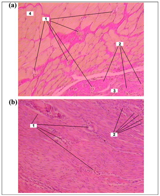
In the experimental group, the muscular fibrils on the skin-metal border showed signs of atrophy; the space between muscular fibrils contained a significant quantity of connective tissue elements (Figure 11(a)). In the control group, the skin on the border with the implant had moderate edema and scar alteration. Weak lymphocyte infiltration was developed in the muscular tissues. A dense connective-tissue capsule with weak lymphocyte infiltration was formed around the implant (Figure 11(b)).
Figure 11.
Day 28 after pylon implantation. (a) Muscular and connective tissues in experimental group (Van Gizon staining ×100): 1 = capillaries, 2 = neutrophils, 3 = connective tissue on border with pylon, 4 = muscular tissue. (b) Connective tissue capsule around implant in control group (Hematoxylin-eosin staining ×100): 1 = capillaries, 2 = neutrophils.
Day 42 After Operation
In the experimental group, we observed connective tissues in the space between muscular fibrils. Muscular tissues were not infiltrated. The connective tissue (thickness 250–500 μm) with separate muscular fibrils adjoined the implant (Figure 12(a)).
Figure 12.
Day 42 after pylon implantation. (a) Muscular tissue in experimental group (Van Gizon staining ×100): 1 = muscular tissue, 2 = connective tissue between muscular fibrils, 3 = blood vessels. (b) Connective tissue capsule around implant in control group (Hematoxylin-eosin staining ×100): 1 = capillaries, 2 = neutrophils. (c) Electron scan of cross section of implant in experimental group (×200): 1 = fine wire of implant, 2 = pores of implant, 3 = tissue elements in pores.
In the control group (Figure 12(b)), edema and scar alteration on the metal-skin border were similar to that observed on day 28 (Figure 11(b)). Electron scanning of the cross section of the implant in the experimental group showed ingrowth of the tissue in the pores of the pylon (Figure 12(c)).
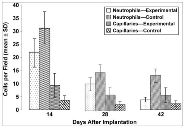
The calculated mean ± SD of neutrophils per field and capillaries per field for days 14, 28, and 42 after implantation are presented in Table 2, with a graph in Figure 13. We compared the experimental and control groups with a Student’s t-test for mean values.
Table 2.
Neutrophil and capillary count (mean ± standard deviation) in experimental group (rats implanted with porous pylon) and control group (rats implanted with solid pylon).
| Days After Implantation | Neutrophils per Field
|
Capillaries per Field
|
||
|---|---|---|---|---|
| Experimental | Control | Experimental | Control | |
| 14 | 21.88 ± 5.92 | 31.27 ± 6.86 | 9.32 ± 7.15 | 6.44 ± 3.62 |
| 28 | 10.02 ± 3.27 | 14.37 ± 7.42 | 5.90 ± 3.44 | 2.32 ± 1.02 |
| 42 | 3.80 ± 2.00 | 13.05 ± 3.27 | 5.62 ± 3.53 | 2.32 ± 1.02 |
Figure 13.
Neutrophil and capillary count in experimental and control groups. SD = standard deviation.
Assuming that both characteristics were independent and normally distributed, we found that the differences in the experimental and control group mean values were statistically significant on days 14, 28, and 42 (p < 0.05). Namely, the number of neutrophils was greater and the number of capillaries was smaller in the control group than in the experimental group. Within the groups, both characteristics demonstrated statistical significance, decreasing along the timeline after implantation, except for the number of capillaries on days 28 and 42, which were not significantly different.
Discussion
Formation of hair follicles in the very proximity of the porous pylon can indicate the sufficiency of wound healing in surrounding skin. That conclusion is supported by a recent mouse study that identified a specific K17-binding protein in keratinocytes that regulates many cellular processes [27]. Specifically, the distribution of K17 overlapped within the hair follicles of intact skin tissue, and notably, in wounded epithelial tissues.
While the number of capillaries in the experimental group was greater than in the control group at each of the three postsurgery time points, overall capillary development in both the experimental and control groups was characterized by a decrease in their number over time. The most noticeable decrease was observed between days 14 and 28 (Table 2, Figure 13). We suggest that this overall decrease in the number of capillaries can be explained by the formation of scar tissues around the implant during wound healing after the surgery. In the initial period of healing, the fast growth in mass of the granulation tissues requires an extra blood supply, which explains the relatively high number of capillaries at day 14. Once the scar tissues are developing (days 28 and 42), the need for blood supply, and consequently the number of capillaries, decreases. Because the tissues surrounding the porous implants in the experimental group had the option to migrate inside the implant, scar tissue developed less at each time point compared with the control group with the solid implant.
The rat model used in the current study is well accepted in human-prosthesis interface and human osseointegration research at the initial preclinical stage [28]. Before clinical studies, more studies on both rodent and nonrodent animals are required [9,11,29].
In Vitro Human Skin-Cell Growth Study
Results
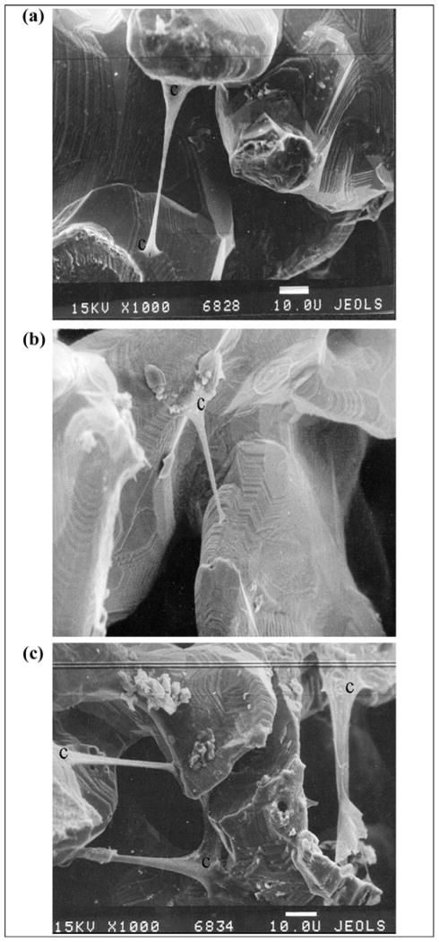
Human fibroblasts migrated inside the porous samples from the surrounding collagen gel (Figure 14). Minimal migration was observed on the samples pretreated with type I collagen, made of the tendon of rat tail (group 1) (Figure 14(b)). Greater migration was observed in the untreated samples (group 3) (Figure 14(a)) and on the samples pretreated with human fibrin (group 2) (Figure 14(c)). No substantial difference was found between groups 2 and 3 (Figure 14(a) and (c)).
Figure 14.
Migration of human fibroblasts within (a) untreated sample of porous composite pylon (skin and bone integrated pylon 2 [SBIP-2]), ×1,000; (b) sample of porous composite pylon SBIP-2 pretreated with type I collagen, ×1,000; and (c) sample of porous composite pylon SBIP-2 pretreated with human fibrin, ×1,000. c = human fibroblasts.
Discussion
As our previous study with human dermal fibroblasts demonstrated, a 100 percent confluent monolayer of cells was apparent 7 days after seeding on the outer and inner particles of the porous titanium pellets treated with different proteins [21]. The size of the particles and porosity in the pellets were similar to those used in the current study with SBIP-2. The in vitro spread and growth of the human cells inside the SBIP-2 structure further suggest the feasibility of integration of the titanium implant with the skin and bone of a recipient whose prosthesis is directly attached.
Formation of sustainable skin around, and possibly inside, a porous implanted pylon requires effective wound healing. In this process, the skin fibroblasts synthesize and maintain the extracellular matrix composed of structural and functional proteins, including collagen. The extracellular matrix, with its natural three-dimensional structure and composition, provides a scaffold for cell proliferation [30–32]. Such biological scaffolds have been shown to resist deliberate bacterial contamination [33–34], which is essential for creation of a barrier against infection in the direct skeletal attachment of a limb prosthesis. Therefore, in our in vitro experiments, we investigated whether collagen and fibrin treatment of a porous implant would affect migration of skin cells inside the structure of the implant.
The titanium implants have been proven biocompatible with osteoblasts, chondrocytes, and stromal cells in in vitro studies [7,35–37]. Enhancement of the interface between the implants and cells has been attempted by creating open pores on the implant surface [38], making fiber metal composites [39], and treating the surface of the implants with calcium phosphates [40–41] by varying thermal conditions [42]. The interface was evaluated by cell adhesion, proliferation, and differentiation [35,43], as well as by cell morphology and cytoskeleton by scanning or confocal microscopy by synthesis of the proteins of the extracellular matrix and proteoglycans [36]. In vivo, the biocompatibility has been evaluated histologically [7,44]. To improve interface with the cells, researchers in one study treated titanium implants with the enamel matrix Emdogain (experimental group) and a vehicle gel (propylene glycol alginate [control group]) and injected them into the surgically prepared implant site before inserting the implant into the rabbits’ femur and tibia. They concluded that the Emdogain did not contribute to bone formation around the titanium implants [45]. The porous coating on the interface had a positive effect, as demonstrated by the observation that all osteoblast activity indicators were significantly greater in the porous coated region compared with the host bone region [46]. However, titanium implants that were coated with the highly biocompatible hydroxyapatite and developed in the presence of bacteria became more severely infected than noncoated titanium implants [47]. The results demonstrated no benefit of Emdogain treatment on bone formation around titanium implants. Xenogenic and allogenic extracellular matrixes were used as the bioscaffold for the reconstruction of different damaged tissues. Extracellular matrix-associated tissue remodeling promotes angiogenesis, recruitment of circulating progenitor cells, rapid scaffold degradation and constructive remodeling of damaged tissues, and cell adhesion and migration [30,48]. Since treatment of the implant surface by the extracellular matrix components has the potential for better cell growth [49], it may be applied in the future to the implantable prosthetic pylon as well. An in vitro study with titanium foam for spine fusion demonstrated the ingrowth of human osteoblasts through the interconnected porosity of a metal structure [50].
CONCLUSIONS
We developed a composite porous pylon with a strength exceeding that of human bone.
Wires provided noticeable reinforcement to the porous pylon.
With the temperature controlled, the composite porous/solid titanium structures can show bend strength that significantly exceeds that of human bone yet still provide the porosity and pore size conditions necessary for growth of the skin tissue.
The animal study with the composite porous prosthetic pylon demonstrated ingrowth of skin cells within the pylon and the potential for creation of a barrier to infection.
Clinical observations of less inflammation outside the implanted porous pylon compared with the solid pylon agree with the smaller number of neutrophil-like cells in the tissues close to the pylon’s surface.
More capillaries in the experimental rat group (implanted with the porous pylon) may indicate increased blood supply because of the growth of cells inside the pores of the implant.
The composite porous structure can be used in devices for percutaneous transfer of vital and therapeutic substances, signals, and necessary forces and moments from the outer delivery to the body.
Our in vitro study demonstrated that the composite structure can act as a scaffold for human skin cells.
Acknowledgments
The mechanical tests were performed at the Materials Characterization Laboratory of Leach & Garner Company, North Attleboro, Massachusetts.
This material was based on work supported in part by the National Institutes of Health (grant 1R43HD057492-01A1) and with resources and the use of facilities at Poly-Orth International, Sharon, Massachusetts, and ADMA Products Inc, Hudson, Ohio.
Abbreviations
- SBIP
skin and bone integrated pylon
- SD
standard deviation
Footnotes
The authors have declared that no competing interests exist.
References
- 1.Levy SW. Skin problems of amputee. St. Louis (MO): Warren H. Green; 1983. [Google Scholar]
- 2.Eriksson E, Brånemark PI. Osseointegration from the perspective of the plastic surgeon. Plast Reconstr Surg. 1994;93(3):626–37. [PubMed] [Google Scholar]
- 3.Brånemark R, Brånemark PI, Rydevik B, Myers RR. Osseointegration in skeletal reconstruction and rehabilitation: A review. J Rehabil Res Dev. 2001;38(2):175–81. [PubMed] [Google Scholar]
- 4.Sooriakumaran S, Robinson KP, Ward DA. Pattern of infection of transfemoral osseointegration. Proceedings of the 11th World Congress, International Society for Prosthetics and Orthotics; 2004 Aug 1–6; Wanchai, Hong Kong. Hong Kong: ISPO; 2004. p. 252. [Google Scholar]
- 5.Murphy EF. History and philosophy of attachment of prostheses to the musculo-skeletal system and of passage through the skin with inert materials. J Biomed Mater Res. 1973;7(3):275–95. doi: 10.1002/jbm.820070319. [DOI] [PubMed] [Google Scholar]
- 6.Shin Y, Akao M. Tissue reactions to various percutaneous materials with different surface properties and structures. Artif Organs. 1997;21(9):995–1001. doi: 10.1111/j.1525-1594.1997.tb00514.x. [DOI] [PubMed] [Google Scholar]
- 7.Deligianni DD, Katsala ND, Koutsoukos PG, Missirlis YF. Effect of surface roughness of hydroxyapatite on human bone marrow cell adhesion, proliferation, differentiation and detachment strength. Biomaterials. 2001;22(1):87–96. doi: 10.1016/s0142-9612(00)00174-5. [DOI] [PubMed] [Google Scholar]
- 8.Haggstrom E, Brånemark M. The osseointegrated transfemoral prosthesis. Proceedings of the 11th World Congress, International Society for Prosthetics and Orthotics; 2004 Aug 1–6; Wanchai, Hong Kong. Hong Kong: ISPO; 2004. [Google Scholar]
- 9.Yu C, Sun Y, Bradfield J, Fiordalisi I, Harris GD. A novel percutaneous barrier device that permits safe subcutaneous access. ASAIO J. 1999;45(6):531–34. doi: 10.1097/00002480-199911000-00005. [DOI] [PubMed] [Google Scholar]
- 10.Yu C, Harris GD. The LPD-II: A modified locked percutaneous device that permits safe subcutaneous access. ASAIO J. 2001;47(1):25–29. doi: 10.1097/00002480-200101000-00007. [DOI] [PubMed] [Google Scholar]
- 11.Yu C, Harris GD, Sun Y. An alternative design of locked percutaneous device for skeletal extension through skin. Artif Organs. 2003;27(3):267–71. doi: 10.1046/j.1525-1594.2003.07094.x. [DOI] [PubMed] [Google Scholar]
- 12.Pendegrass CJ, Goodship AE, Blunn GW. Development of a soft tissue seal around bone-anchored transcutaneous amputation prostheses. Biomaterials. 2006;27(23):4183–91. doi: 10.1016/j.biomaterials.2006.03.041. [DOI] [PubMed] [Google Scholar]
- 13.Pendegrass CJ, Goodship AE, Price JS, Blunn GW. Nature’s answer to breaching the skin barrier: An innovative development for amputees. J Anat. 2006;209(1):59–67. doi: 10.1111/j.1469-7580.2006.00595.x. [DOI] [PMC free article] [PubMed] [Google Scholar]
- 14.Pitkin M, Raykhtsaum G, inventors. United States patent US N.20070071788. Skin integrated device. 2005 (in process)
- 15.Pitkin M, Raykhtsaum G, Galibin OV, Protasov MV, Chihovskaya JV, Belyaeva IG. Skin and bone integrated prosthetic pylon: A pilot animal study. J Rehabil Res Dev. 2006;43(4):573–80. doi: 10.1682/jrrd.2005.05.0160. [DOI] [PMC free article] [PubMed] [Google Scholar]
- 16.Yamada H, Evans FG. Strength of biological materials. Baltimore (MD): Williams and Wilkins Company; 1970. [Google Scholar]
- 17.Handbook of steel construction. Willowdale (Ontario): Canadian Institute of Steel Construction; 1977. [Google Scholar]
- 18.Bateni H, Olney SJ. Kinematic and kinetic variations of below-knee amputee gait. J Prosthet Orthot. 2002;14(1):2–10. [Google Scholar]
- 19.Smidt GL. Gait in rehabilitation. New York (NY): Churchill Livingstone; 1990. [Google Scholar]
- 20.Perry J, Boyd LA, Rao SS, Mulroy SJ. Prosthetic weight acceptance mechanics in transtibial amputees wearing the Single Axis, Seattle Lite, and Flex Foot. IEEE Trans Rehabil Eng. 1997;5(4):283–89. doi: 10.1109/86.650279. [DOI] [PubMed] [Google Scholar]
- 21.Yudintseva N, Blinova M, Pinaev G, Potokin I, Pitkin M, Raykhtsaum G. Characterization and morphology of cells cultivated on titanium implants of different structures. 2nd World Congress on Regenerative Medicine; 2005 May 18–20; Leipzig, Germany. Milan (Italy): International Journal of Artificial Organs; 2005. [Google Scholar]
- 22.Swanson SR. Introduction to design and analysis with advanced composite materials. Upper Saddle River (NJ): Prentice Hall; 1997. [Google Scholar]
- 23.Li L, Aubertin M. A general relationship between porosity and uniaxial strength of engineering materials. Can J Civ Eng. 2003;30(4):644–58. [Google Scholar]
- 24.Waite JH, Lichtenegger HC, Stucky GD, Hansma P. Exploring molecular and mechanical gradients in structural bioscaffolds. Biochemistry. 2004;43(24):7653–62. doi: 10.1021/bi049380h. [DOI] [PMC free article] [PubMed] [Google Scholar]
- 25.Murray GA, Semple JC. Transfer of tensile loads from a prosthesis to bone using porous titanium. J Bone Joint Surg Br. 1981;63-B(1):138–41. doi: 10.1302/0301-620X.63B1.7204467. [DOI] [PubMed] [Google Scholar]
- 26.Bünger MH, Foss M, Erlacher K, Li H, Zou X, Langdahl BL, Bünger C, Birkedal H, Besenbacher F, Pedersen JS. Bone nanostructure near titanium and porous tantalum implants studied by scanning small angle X-ray scattering. Eur Cell Mater. 2006;12:81–91. doi: 10.22203/ecm.v012a10. [DOI] [PubMed] [Google Scholar]
- 27.Kim S, Wong P, Coulombe PA. A keratin cytoskeletal protein regulates protein synthesis and epithelial cell growth. Nature. 2006;441(7091):362–65. doi: 10.1038/nature04659. [DOI] [PubMed] [Google Scholar]
- 28.Brånemark R, Ohrnell LO, Nilsson P, Thomsen P. Biomechanical characterization of osseointegration during healing: An experimental in vivo study in the rat. Biomaterials. 1997;18(14):969–78. doi: 10.1016/s0142-9612(97)00018-5. [DOI] [PubMed] [Google Scholar]
- 29.Brånemark R, Ohrnell LO, Skalak R, Carlsson L, Brånemark PI. Biomechanical characterization of osseointegration: An experimental in vivo investigation in the beagle dog. J Orthop Res. 1998;16(1):61–69. doi: 10.1002/jor.1100160111. [DOI] [PubMed] [Google Scholar]
- 30.Badylak SF. The extracellular matrix as a scaffold for tissue reconstruction. Semin Cell Dev Biol. 2002;13(5):377–83. doi: 10.1016/s1084952102000940. [DOI] [PubMed] [Google Scholar]
- 31.Fisher JP. Tissue engineering. New York (NY): Springer; 2006. Aegean Conferences. [Google Scholar]
- 32.Valentin JE, Badylak JS, McCabe GP, Badylak SF. Extracellular matrix bioscaffolds for orthopaedic applications. A comparative histologic study. J Bone Joint Surg Am. 2006;88(12):2673–86. doi: 10.2106/JBJS.E.01008. [DOI] [PubMed] [Google Scholar]
- 33.Brennan EP, Reing J, Chew D, Myers-Irvin JM, Young EJ, Badylak SF. Antibacterial activity within degradation products of biological scaffolds composed of extracellular matrix. Tissue Eng. 2006;12(10):2949–55. doi: 10.1089/ten.2006.12.2949. [DOI] [PMC free article] [PubMed] [Google Scholar]
- 34.Sarikaya A, Record R, Wu CC, Tullius B, Badylak S, Ladisch M. Antimicrobial activity associated with extracellular matrices. Tissue Eng. 2002;8(1):63–71. doi: 10.1089/107632702753503063. [DOI] [PubMed] [Google Scholar]
- 35.Vehof JW, Spauwen PH, Jansen JA. Bone formation in calcium-phosphate-coated titanium mesh. Biomaterials. 2000;21(19):2003–9. doi: 10.1016/s0142-9612(00)00094-6. [DOI] [PubMed] [Google Scholar]
- 36.Ciolfi VJ, Pilliar R, McCulloch C, Wang SX, Grynpas MD, Kandel RA. Chondrocyte interactions with porous titanum alloy and calcium polyphosphate substrates. Biomaterials. 2003;24(26):4761–70. doi: 10.1016/s0142-9612(03)00373-9. [DOI] [PubMed] [Google Scholar]
- 37.Wang J, Layrolle P, Stigter M, De Groot K. Biomimetic and electrolytic calcium phosphate coatings on titanium alloy: Physicochemical characteristics and cell attachment. Biomaterials. 2004;25(4):583–92. doi: 10.1016/s0142-9612(03)00559-3. [DOI] [PubMed] [Google Scholar]
- 38.Lueck RA, Galante J, Rostoker W, Ray RD. Development of an open pore metallic implant to permit attachment to bone. Surg Forum. 1969;20:456–57. [PubMed] [Google Scholar]
- 39.Galante J, Rostoker W, Lueck RA, Ray RD. Sintered fiber metal composites as a basis for attachment of implants to bone. J Bone Joint Surg Am. 1971;53(1):101–14. [PubMed] [Google Scholar]
- 40.Pilliar RM, Filiaggi MJ, Wells JD, Grynpas MD, Kandel RA. Porous calcium polyphosphate scaffolds for bone substitute applications—In vitro characterization. Biomaterials. 2001;22(9):963–72. doi: 10.1016/s0142-9612(00)00261-1. [DOI] [PubMed] [Google Scholar]
- 41.Chang YL, Stanford CM, Wefel JS, Keller JC. Osteoblastic cell attachment to hydroxyapatite-coated implant surfaces in vitro. Int J Oral Maxillofac Implants. 1999;14(2):239–47. [PubMed] [Google Scholar]
- 42.Fujibayashi S, Neo M, Kim HM, Kokubo T, Nakamura T. Osteoinduction of porous bioactive titanium metal. Biomaterials. 2004;25(3):443–50. doi: 10.1016/s0142-9612(03)00551-9. [DOI] [PubMed] [Google Scholar]
- 43.Serro AP, Fernandes AC, Saramago B, Lima J, Barbosa MA. Apatite deposition on titanium surfaces—The role of albumin adsorption. Biomaterials. 1997;18(14):963–68. doi: 10.1016/s0142-9612(97)00031-8. [DOI] [PubMed] [Google Scholar]
- 44.Cho SA, Jung SK. A removal torque of the laser-treated titanium implants in rabbit tibia. Biomaterials. 2003;24(26):4859–63. doi: 10.1016/s0142-9612(03)00377-6. [DOI] [PubMed] [Google Scholar]
- 45.Franke Stenport V, Johansson CB. Enamel matrix derivative and titanium implants. J Clin Periodontol. 2003;30(4):359–63. doi: 10.1034/j.1600-051x.2003.00326.x. [DOI] [PubMed] [Google Scholar]
- 46.Bloebaum RD, Willie BM, Mitchell BS, Hofmann AA. Relationship between bone ingrowth, mineral apposition rate, and osteoblast activity. J Biomed Mater Res A. 2007;81(2):505–14. doi: 10.1002/jbm.a.31087. [DOI] [PubMed] [Google Scholar]
- 47.Oosterbos CJ, Vogely HCh, Nijhof MW, Fleer A, Verbout AJ, Tonino AJ, Dhert WJ. Osseointegration of hydroxyapatite-coated and noncoated Ti6Al4V implants in the presence of local infection: A comparative histomorphometrical study in rabbits. J Biomed Mater Res. 2002;60(3):339–47. doi: 10.1002/jbm.1288. [DOI] [PubMed] [Google Scholar]
- 48.Gorelik JV, Cherepanova OA, Voronkina IV, Diakonov IA, Blinova MI, Pinaev GP. Laminin-2/4 from human placenta is a better adhesion agent for primary keratinocytes than laminin-1 from EHS sarcoma. Cell Biol Int. 2001;25(5):395–402. doi: 10.1006/cbir.2000.0642. [DOI] [PubMed] [Google Scholar]
- 49.Clark RA. The molecular and cellular biology of wound repair. New York (NY): Plenum Press; 1996. [Google Scholar]
- 50.Müller U, Imwinkelried T, Horst M, Sievers M, Graf-Hausner U. Do human osteoblasts grow into open-porous titanium? Eur Cell Mater. 2006;11:8–15. doi: 10.22203/ecm.v011a02. [DOI] [PubMed] [Google Scholar]


