Abstract
OBJECTIVE
To determine how the size and location of coupling defects caught between the therapy head of a lithotripter and the skin of a surrogate patient (acoustic window of a test chamber) affect the features of shock waves responsible for stone breakage.
METHODS
Model defects were placed in the coupling gel between the therapy head of a Dornier Compact-S electromagnetic lithotripter and the Mylar window of a water-filled coupling test system.
A fiber-optic hydrophone was used to measure acoustic pressures and map the lateral dimensions of the focal zone of the lithotripter.
The effect of coupling conditions on stone breakage was assessed using Gypsum model stones.
RESULTS
Stone breakage decreased in proportion to the area of the coupling defect; a centrally located defect blocking only 18% of the transmission area reduced stone breakage by an average of almost 30%.
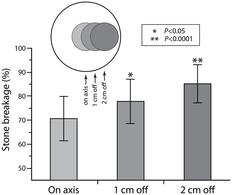
The effect on stone breakage was greater for defects located on-axis and decreased as the defect was moved laterally; an 18% defect located near the periphery of the coupling window (2.0 cm off-axis) reduced stone breakage by only ~15% compared to when coupling was completely unobstructed.
Defects centered within the coupling window acted to narrow the focal width of the lithotripter; an 8.2% defect reduced the focal width ~30% compared to no obstruction (4.4 mm versus 6.5 mm).
Coupling defects located slightly off center disrupted the symmetry of the acoustic field; an 18% defect positioned 1.0 cm off-axis shifted the focus of maximum positive pressure ~1.0 mm laterally.
Defects on and off-axis imposed a significant reduction in the energy density of shock waves across the focal zone.
CONCLUSIONS
In addition to blocking the transmission of shock wave energy, coupling defects also disrupt the properties of shock waves that play a role in stone breakage, including the focal width of the lithotripter and the symmetry of the acoustic field; the effect is dependent on the size and location of defects, with defects near the center of the coupling window having the greatest effect.
These data emphasize the importance of eliminating air pockets from the coupling interface, particularly defects located near the center of the coupling window.
INTRODUCTION
The quality of acoustic coupling in shock wave lithotripsy (SWL) is often overlooked and may be one of the most important factors affecting treatment outcomes (1,2). SWL can be very effective in breaking stones but only if the shock waves (SWs) can get to the target. In early lithotripters such as the Dornier HM3 the patient was immersed in a water bath, providing an ideal medium for SW propagation. Modern lithotripters on the other hand are dry-head devices in which the cushion of the treatment head must be coupled, usually with gel or oil, to the skin of the patient. Unfortunately, air can get trapped at the coupling interface and this interferes with SW transmission to the patient (3,4).
Reports have suggested that newer lithotripters are not nearly as effective as the Dornier HM3 (1, 5–7). Clearly there are multiple factors that distinguish one lithotripter from the next so it is difficult to know what contributes to higher success rates with the HM3. The HM3 is not the most powerful lithotripter nor does the acoustic output or dimensions of the focal volume distinguish this lithotripter from most others. The HM3 is, however, the only lithotripter that employs a complete immersion water bath, the only lithotripter where the quality of coupling is not potentially problematic, and this could be the primary reason the HM3 has proven to be more effective than newer machines.
In previous studies with dry-head lithotripters we have shown that air pockets caught at the coupling interface between the cushion of the treatment head and the acoustic window (surrogate skin) of the test tank interfere with the transmission of SW energy (8). As the area occupied by air pockets increased, acoustic pressure at the focal point of the lithotripter decreased, as did the efficiency in breakage of model stones. There was considerable variability in the system in that every coupling attempt yielded a different pattern of air pockets with defects of different shape, size and location depending on how the gel was handled and applied. This was found to be the case for tests using a Mylar membrane as surrogate skin, but also when a treatment cushion affixed to a viewing port was pushed against the skin of a volunteer. It was also observed that coupling attempts having a similar total area occupied by air pockets could yield stone breakage values differing by greater than 30%, suggesting that not only does the area of coupling defects matter, but perhaps that the location of the air pockets is also important (9).
Air pockets caught at the coupling interface are acoustically opaque and block the SW transmission path, but they also have smooth or regular edges that could create diffraction with the potential to further disrupt the acoustic field at the target (10). Since the mechanisms of SW action in stone breakage and tissue damage are dependent on the acoustic output and dimensions of the focal zone of the lithotripter there is value in learning more about the potential mechanistic effects of defects at the coupling interface. Therefore, we undertook a study to assess the role that size, shape and location of coupling defects may play in lithotripter performance.
METHODS
Lithotripter, Coupling Defects and Stone Breakage
Studies were performed using a Dornier Compact-S electromagnetic lithotripter (Dornier MedTech, Kennesaw, GA, USA) and in vitro test system consisting of an acrylic water tank (length 50 cm × width 52 cm × depth 40 cm) with a 0.13-mm-thick Mylar acoustic window that coupled with the therapy head of the lithotripter at ~45 degrees (see http://www.ncbi.nlm.nih.gov/pmc/articles/PMC2435067/figure/F1/). This in vitro system has been used previously to simulate coupling of the lithotripter treatment head to the skin of a patient (8,9). Water in the test tank (room temperature, 21–23°C) was degassed continuously with a multi-pinhole degasser, maintaining oxygen content at about 25–30% saturation (2.2–2.7 parts per million). LithoClear® (Sonotech, Bellingham, MA, USA) gel was used as the coupling medium. The transparent Mylar membrane allowed visual inspection of coupling quality from within the water tank. To achieve coupling free from air pockets a mound of gel was applied to the treatment head, which was then inflated to contact the Mylar window (9). Bubbles caught at the interface were gently pushed by hand to the periphery of the coupling field.
Air pocket defects at the coupling interface were modeled using circular disks and freeform shapes cut from 2-mm-thick Styrofoam sheet stock. The Styrofoam was secured to the cushion of the treatment head, gel was applied, coupling was achieved and extraneous bubbles were removed from the field by hand. The acoustic impedance mismatch of Styrofoam is similar to that of air and, unlike air bubbles, these model defects did not break up or drift during repetitive exposure to SWs. This permitted systematic tests of the size and location of coupling defects.
The effect of coupling conditions on the breakage of Gypsum model stones was assessed by determining the percent of stone mass retained in a 2 mm mesh basket following exposure to SWs (400 SWs, Power level 3, 60 SW/min) (8,11).
Acoustics Measurements
A fiber-optic probe hydrophone (FOPH) (model 500, RP Acoustics, Leutenbach, Germany) was used to determine acoustic pressures. Measurements were taken at the focal plane of the lithotripter estimated by X-ray alignment and refined by determining the point of maximum pressure amplitude. The lithotripter was fired at power level 3 (PL-3), 60 SW/min and sets of 10 or more waveforms stored using a Tektronix digital oscilloscope (TDS 5034, Textronix, Beaverton, OR, USA) (8). For mapping of the acoustic field the tip of the FOPH was moved in 1.0 mm steps over a total excursion of 10–12 mm. Average waveforms were calculated by aligning pulses to the coincidence of the half amplitude of the shock fronts (8,12). Energy density within the focal zone was derived from mapping data by calculating the time integral of pressure squared over the duration of the positive pressure phase of the pulse. Energy density values were used to estimate total energy of the acoustic pulse across the focal width (6.5 mm diameter) at the focal plane. Calculations were also made for a 10 mm zone centered on-axis to estimate energy that would be delivered to a ~1.0 cm stone targeted at the focal point.
Characterization of the Coupling Window
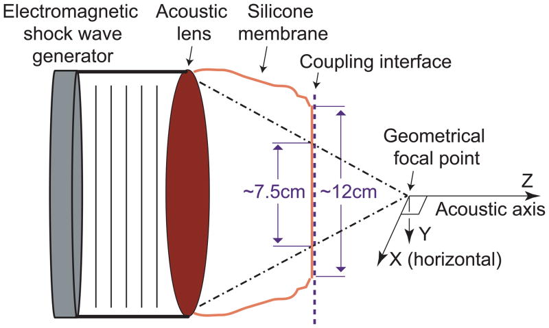
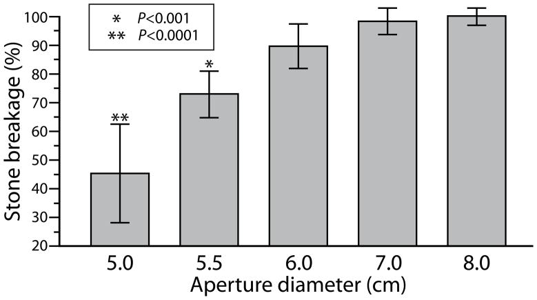
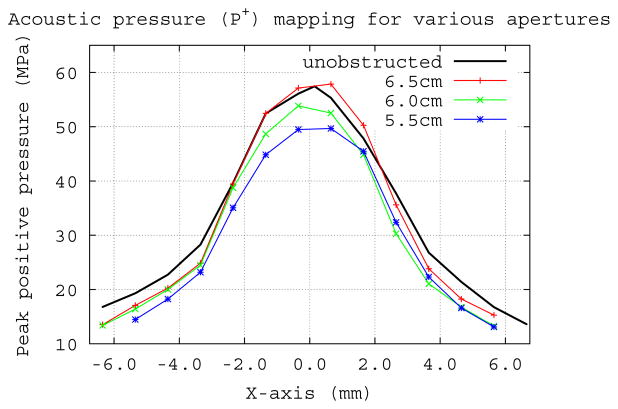
A schematic of the coupling system is shown in Fig. 1. Since the contact surface between the lithotripter cushion and Mylar membrane of the test tank measured larger (~12 cm diameter) than the estimated window (~7.5 cm) for passage of the majority of acoustic energy from the shock source, we determined the size of the effective coupling window by measuring the efficiency of stone breakage for coupling windows of different diameter. Styrofoam sheets with open apertures of progressively narrower internal diameter (8.0 to 5.0 cm) were positioned at the coupling interface. Only when the window was narrower than ~7.0 cm was breakage reduced compared to unobstructed coupling (Fig. 2). But, mapping of peak positive pressure (P+) at the focal plane did not show big differences for the various apertures (Fig. 3). The P+ profiles for the 6.5 cm and 6.0 cm apertures were very close to that with no obstruction and there was only a slight reduction in amplitude when the coupling window was further reduced to 5.5 cm diameter. Values for peak negative pressure (P−) across the focal width (6.5 mm) showed little effect even for the narrowest window, measuring −3.9±0.6 MPa for unobstructed coupling and −4.1±0.3, −3.5±0.3, and −2.9±0.5 MPa for apertures of 6.5, 6.0 and 5.5 cm respectively. However, the acoustic pulse energy at the focal plane showed a substantial reduction as the aperture (i.e. coupling window) was narrowed. Whereas, the pulse energy across the focal width was 16.3 mJ with no obstruction, apertures of 6.5, 6.0 and 5.5 cm gave values of 12.1, 10.9 and 9.3 mJ, respectively. Values across the 10 mm “stone target zone” showed a similar trend measuring 30.7 mJ (unobstructed) and 21.9, 19.5 and 16.4 mJ for apertures of 6.5, 6.0 and 5.5 cm.
Figure 1.
Schematic of the coupling system. The shock wave generator is 14.0 cm in diameter, and the focal length of the Compact-S is 13.0 cm. In the experimental setup, the coupling interface was located ~7.0 cm from the focal point and was considerably wider (~12 cm) than the acoustic window of the lithotripter (estimated at ~7.5 cm by geometrical acoustics).
Figure 2.
Efficiency of stone breakage for coupling windows created using circular apertures of different diameter. Vertical axis shows percent breakage normalized to breakage when the coupling interface was entirely unobstructed (no fixed aperture or other coupling defect). Stones were treated with 400 SWs (PL-3, 60 SW/min). Number of stones broken for each group was 6 or 7. Legend indicates P-values for Tukey test, showing significant differences as compared with the 8.0 cm aperture, but breakage was also reduced with 6.0 cm aperture, as judged by t-test showing the mean to be lower than 100% (P<0.05).
Figure 3.
Pressure (P+) mapping at the focal plane for different coupling windows, using Styrofoam apertures to block SW energy over the remainder of the 12 cm diameter coupling interface. Only when the window was reduced to 5.5 cm in diameter was there a noteworthy reduction in P+ across the width of the focal zone.
Because stone breakage was not affected by the 7.0 cm aperture we defined this as the “effective coupling window”, using this diameter to calculate the percent area occupied by a defect. All experiments with coupling defects were performed without restrictive apertures, that is, otherwise unobstructed.
Statistical Methods
Data for stone breakage results were compared using linear regression, analysis of variance (with post-hoc testing using the Tukey-Kramer HSD test), or t-test as appropriate. Error bars indicate standard deviation from the mean. Calculations were completed using JMP 9.0 (SAS Institute, Cary, NC, USA).
RESULTS
Coupling defects affected both the efficiency of stone breakage and the characteristics of the acoustic field, with the effect dependent on the size and location of the defects within the coupling window. Defects located on-axis had the greatest effect.
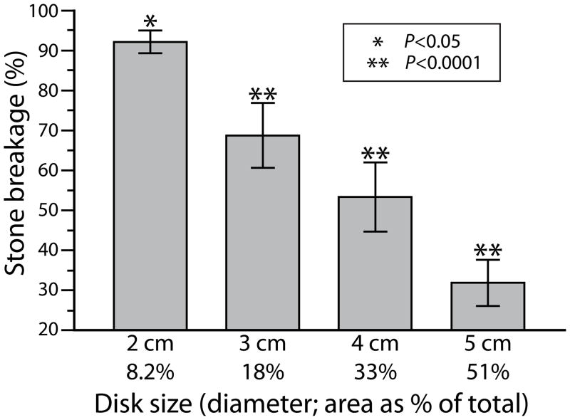
Stone breakage decreased in proportion to the area of the coupling defects. Figure 4 shows stone breakage results when defects measuring 2.0–5.0 cm in diameter were positioned on-axis in the coupling window. Stones held in a 2 mm mesh basket were treated with 400 SWs and the mass of fragments retained in the basket was determined. There was a near linear relationship between breakage and the area of the coupling window occupied by defect, and a defect of only ~8% of the coupling surface caused a significant reduction in stone breakage.
Figure 4.
Stone breakage for circular coupling defects of increasing size, positioned on-axis. Vertical scale shows percent breakage normalized to that measured when the coupling interface was entirely free of defects. A defect covering as little as 8% of the coupling window caused a significant reduction in stone breakage. Number of stones broken for each group was 12, except for 5.0 cm disk data, which had only 6 stones. P-values are from Tukey test and show comparison with breakage measured without defect present (data not shown).
Mapping of the acoustic field showed a narrowing of the focal width (−6dB zone) when coupling defects were centered on-axis. Figure 5 shows the lateral distribution of peak positive pressure (P+) measured at the focal plane of the lithotripter for unobstructed coupling and when defects of 1.0, 2.0 and 3.0 cm were centered in the coupling window. When coupling was unobstructed the focal width measured 6.5 mm, and with defects of 1.0, 2.0 and 3.0 cm the focal width was reduced to 5.7, 4.4 and 3.1 mm, respectively.
Figure 5.
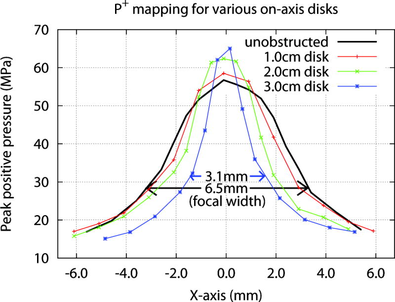
Pressure (P+) mapping at the focal plane for on-axis defects of various sizes. Note that a 3.0 cm defect cut the focal width to less than half (~3.1 mm) compared to when coupling was unobstructed (~6.5 mm). Peak negative pressure (P− not shown) measured −4.1±0.4, −3.1±0.8, and −2.8±0.5 MPa for unobstructed coupling, and 2.0, 3.0 cm disks, respectively.
Narrowing of the focal width was accompanied by a slight increase in P+ at the focus of the lithotripter, and when defects of 1.0, 2.0 and 3.0 cm were in place P + measured 58.5, 62.4 and 65.0 MPa compared to 56.7 MPa for no obstruction. Although the presence of defects produced a slight increase in P+, the acoustic pulse energy delivered to the focal zone was substantially reduced. Defects reduced the energy across the focal width (6.5 mm) from 17.0 mJ for unobstructed coupling to 14.9, 12.8 and 9.3 mJ for defects of 1.0, 2.0 and 3.0 cm, respectively. Thus, a 3.0 cm defect located at the center of the coupling window reduced the energy by ~45% compared to coupling without defects.
The effect of a coupling defect gradually diminished as it was moved further off axis. Figure 6 shows the effect of location on stone breakage for a 3.0 cm defect. When the defect was positioned on-axis, breakage was reduced by ~30% compared to unobstructed coupling. Moving the defect only 1.0 cm laterally improved breakage significantly (p<0.05) while shifting the position of the defect further to the periphery (2.0 cm off-axis) improved breakage to nearly 85% of when coupling was completely unobstructed.
Figure 6.
Effect of defect location on stone breakage. Breakage improved as the 3.0 cm defect was moved progressively toward the periphery of the coupling window. Inset illustrates area of the coupling window blocked by the 3.0 cm defect and position as it was moved laterally 1.0 and 2.0 cm. Number of stones broken for each group was 16 or 18. P-values are from Tukey test and show comparison with on-axis breakage.
Moving a defect a short distance off axis acted to shift the position of P +max off axis. Figure 7 shows lateral mapping data for a 3.0 cm defect. When the defect was positioned 1.0 cm laterally the location of maximum P+ was shifted by ~1.0 mm. Moving the defect to 2.0 cm off-axis eliminated the elevation in P+ and broadened the focal width, but the location of P+max remained skewed. With the defect further off axis (X>3.0 cm, not shown in Fig. 7), the P+ profile recovered to the status with no obstruction; although at this position the defect overlapped slightly the perimeter of the effective coupling window (see Methods). Location of the defect also affected acoustic energy delivered across the focal zone, such that values were lowest with the defect located on-axis (6.7 mJ), and increased as the defect was moved laterally (6.9 mJ at X=1.0 cm, 10.1 mJ at X=2.0 cm, 13.5 mJ at X=3.0 cm). The effect of defect location on total pulse energy was more evident when measured over a 10 mm “stone target zone” at the focal plane, where values were 11.4, 20.0 and 25.9 mJ when the coupling defect was moved 1.0, 2.0 and 3.0 cm, respectively.
Figure 7.
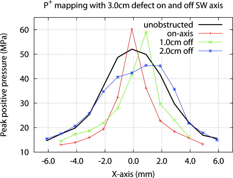
Effect of defect location on acoustic field at the focal plane. A 3.0 cm Styrofoam disk was moved along the horizontal axis (x-axis, positive direction). With the defect on-axis (X=0 cm) P+ was slightly increased, and focal width was narrowed compared to unobstructed coupling. Moving the defect 1.0 cm laterally shifted P+ max ~1.0 mm laterally. Moving the defect to 2.0 cm off-axis eliminated the rise in P+ but the focal point remained skewed. When the defect was moved 3.0 cm laterally (not shown) trace was similar to unobstructed coupling, further suggesting that defects near the periphery of the coupling window have minimal effect on the acoustic field.
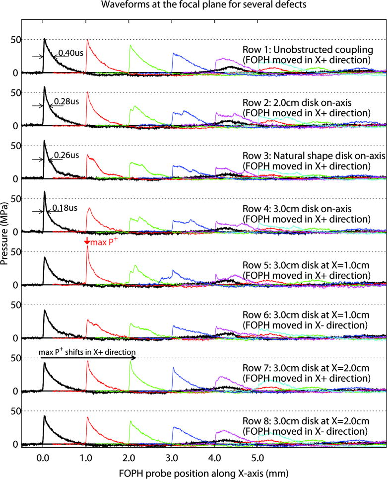
The effect of coupling defects on the acoustic field is further illustrated by pressure profiles collected at the focal plane in 1.0 mm steps perpendicular to the SW-axis (Fig. 8). As the on-axis coupling defect was increased in size (rows 1–4), P+ on-axis (X=0 mm) increased slightly while the duration of the positive-pressure phase (measured at half-amplitude) decreased. Increasing the size of the coupling defect also reduced the amplitude of the off-axis pressure profile.
Figure 8.
Effect of size and location of coupling defects on shock waves collected on-axis and at 1.0 mm steps lateral to the acoustic axis. As defects on-axis were increased in size (rows 1–4), P+ on-axis (X=0 mm) increased slightly while duration of the positive pressure phase (measured at half-amplitude, arrows) decreased from 0.40 μs for unobstructed coupling (row 1) to 0.18 μs for a 3.0 cm defect (row 4). Shock waves measured for a replica of an actual air pocket (natural defect) having area ~25% greater than the 2.0 cm defect showed profiles intermediate between the 2.0 and 3.0 cm circular defects (rows 2, 4). Increase in size of the defect also reduced pressure amplitude off-axis (rows 1–4). When defects were located on-axis, the acoustic field at the focal plane was symmetrical with a maximum at X=0 mm (rows 1–4). Moving the defect off axis disrupted the symmetry of the field, shifting the position of maximum P+ laterally. Placement of a 3.0 cm defect 1.0 cm off-axis shifted maximum P+ ~1.0 mm laterally (row 5, X=1.0 mm) while moving the defect to 2.0 cm lateral position shifted maximum P+ further off axis (row 7, X=1.0 mm and X=2.0 mm) (see Fig. 7).
Moving a defect off-axis disrupted the symmetry of the acoustic field. Shown in Figure 8 are scans with the 3.0 cm defect located on-axis (row 4) and at positions lateral to the SW-axis (rows 5–8). When the defect was located on axis, the acoustic field at the focal plane was symmetrical, with a maximum at X=0 mm (row 4). Moving the defect 1.0 cm off axis disrupted the symmetry of the acoustic field (rows 5, 6), shifting the position of maximum P+ ~1.0 mm laterally (X=1.0 mm, row 5). Moving the defect further off axis restored the symmetry of the acoustic field (rows 7, 8), with pressure amplitudes slightly reduced compared to unobstructed coupling (row 1).
Waveforms for a defect similar in shape to an air pocket caught in the coupling gel showed profiles comparable to those collected for circular defects. Shown in row 3 of Figure 8 is the lateral mapping for a defect of “natural shape”, that is, a shape traced from an air pocket that formed in the coupling gel when the treatment head was brought into contact with the acoustic window of the test tank. The surface area of this defect (3.97 cm2) was slightly larger than the area of the 2.0 cm circular disk, and shock waves measured with this defect of “natural shape” positioned on-axis showed profiles intermediate between the 2.0 and 3.0 cm circular defects (rows 2, 4).
DISCUSSION
The first clinical lithotripter was remarkable in its simplicity. The Dornier HM3 consisted of little more than an underwater spark-gap electrode positioned at the F-1 point of a hemiellipsoidal reflector, with twin fluoroscopy tubes to image and target the stone. By today’s standards this lithotripter was somewhat difficult to use. It was necessary for the patient to recline in a support system suspended from an X-Y-Z gantry then be lowered into the water tank to position the stone at the F-2 point of the reflector. Also, the shock source employed short-lived (~2,000 SWs) open-caged electrodes that due to arc-jitter were inherently inconsistent. Still, this lithotripter was highly effective, more effective than modern machines (1, 2, 5–7). The open water path for acoustic coupling with the HM3 likely had a lot to do with this success.
Current lithotripters are fairly sophisticated. They often have highly consistent shock sources, state-of-the-art imaging, and some are equipped with automated targeting systems. Despite these technical advances the seemingly simple step of coupling the shock source to the patient has emerged as a significant challenge. The problem is not so much in finding a coupling medium that transmits acoustic energy efficiently, but in knowing how to minimize the air pockets that form between the treatment head and the patient’s skin (9). This is where in vitro test systems have proven to be invaluable, and past work has shown that interference by coupling defects can significantly reduce the efficiency of stone breakage (8). The current study begins to address the mechanisms responsible for this effect.
We observed a reduction in stone breakage roughly proportional to the area of the coupling window occupied by defects centered on the acoustic axis. This is what might be predicted considering the relatively uniform distribution of acoustic energy across the aperture of an electromagnetic shock source (13). Results from previous studies in which natural defects in the coupling gel occurred randomly distributed over the coupling interface trended toward such a relationship (8). However, observation that the efficiency of stone breakage could be significantly different for coupling conditions that have the same surface area of defect suggests that the location of defects is important (9). We found that breakage improved when defects were moved progressively off axis, and the effect was dramatic. Shifting the location of an 18% defect just 1.0 cm showed a significant improvement in breakage, while positioning the defect further towards the periphery (2.0 cm off-axis) improved breakage to nearly 85% toward that seen when coupling was entirely unobstructed. This suggests that defects near the edge of the coupling interface are not nearly as important as those located at the center of the coupling window.
In addition to blocking the transmission of acoustic energy, defects at the coupling interface also disrupted the focus, intensity and symmetry of the acoustic field, with the effect dependent on the size and location of the defect. Defects on-axis resulted in a modest increase in P+ but the rise was so slight (< 10% for a 2.0 cm defect) as to likely be of little consequence. More importantly, defects on-axis interfered with shock focusing, effectively narrowing the focal width of the lithotripter. The effect, likely due to diffraction off the sharp edge of the Styrofoam disk, was substantial. A 2.0 cm coupling defect, in the range of air pockets that occur clinically, reduced the focal width by ~30% (4.4 mm compared to 6.5 mm). It is reasonable to consider that a reduction in focal width to this degree could affect breakage efficiency, as it has been shown that initial stone breakage is improved when the focal width is greater than the stone diameter (14,15). In addition, as respiratory motion acts to carry a stone in and out of the target area a narrower focal width reduces the chance of hitting the stone (16).
Coupling defects on axis reduced the delivery of total energy to the focal zone, observed in part as a reduction in pulse width (duration of positive pressure ≥ half the maximum pressure). The effect was fairly substantial as a 3.0 cm defect reduced pulse width to less than half that of when coupling was unobstructed (0.18 μs versus 0.40 μs). Pulse width is a potential factor in stone breakage, as when pulse width is shortened a stone will be exposed to less acoustic energy. Indeed, long pulse duration has been employed as a design feature to enhance dynamic squeezing involved in stone breakage in a broad focal zone, low-pressure lithotripter (17).
The effect of coupling defects on shock wave focusing was largely dependent on location of the defect and most apparent when the defect was on-axis, but lost as the defect was moved progressively toward the perimeter. That is, coupling defects had greatest effect on the acoustic field when located near the center of the coupling window. The location of a coupling defect may also be important in an electrohydraulic lithotripter where the acoustic energy is not uniform across the aperture of the source. That is, in an electrohydraulic lithotripter the pulse originates as a shock but the characteristics of the waveform change as the shock wave converges toward the focal point (18,19). For example, the diffraction wave that originates at the edge of the reflector contributes substantially to the negative tail of the focused shock wave. If defects at the periphery of the coupling window were to block significant segments of the diffraction wave this, conceivably, could alter the amplitude and duration of the negative pressure phase, the portion of the shock wave responsible for cavitation and, thereby, affect stone breakage (20).
In previous studies with this in vitro test system we have observed that when the initial coupling condition was poor, as when the gel was applied by hand or from a squeeze bottle, the quality of coupling tended to improve during the administration of large numbers of shock waves (9). That is, delivery of 1500 SWs could cause some air pockets, particularly millimeter-size bubbles, to collapse. In the current study we used a non-collapsible material (i.e. Styrofoam) to model air-pocket defects. Use of Styrofoam permitted us to more reliably test the effect of defect size and location on the acoustic field, but Styrofoam does not mimic the dynamic nature of bubbles in response to repetitive shock waves and, as such, must be considered a limitation of this study.
One of the practical problems with coupling in clinical SWL is the inability to observe the coupling interface. One simply cannot see the contact surface between the rubber boot of the therapy head and the skin of the patient, and this makes coupling a hit or miss proposition. Recently, however, investigators have reported use of a remote camera positioned inside the treatment head of a lithotripter to monitor the quality of coupling (4). Consistent with in vitro studies this report showed that quality of coupling is variable, with area of air pocket defects ranging from less than 5% to greater than 20% of the coupling window. The ability to directly monitor coupling will hopefully lead to improved coupling methods, but may also pose the question of what constitutes good coupling. That is, when defects are observed to be present, what degree of coverage is acceptable? Our findings begin to address this, and suggest that for electromagnetic lithotripters similar in design to the Dornier Compact-S, defects near the center of the coupling window have greater potential to disrupt the acoustic field than do defects toward the periphery. Provided with a means to observe the quality of coupling one would strive to eliminate all defects. Still, clearing the central 6–7 cm of the field would likely improve the chances of a good result. Determining how much of the coupling interface can be occupied by air pockets and still yield an acceptable result during patient treatment will need to be determined, likely on a system-by-system basis.
What’s known on the subject? And What does the study add?
In shock wave lithotripsy air pockets tend to get caught between the therapy head of the lithotripter and the skin of the patient. Defects at the coupling interface hinder the transmission of shock wave energy into the body, reducing the effectiveness of treatment. This in vitro study shows that ineffective coupling not only blocks the transmission of acoustic pulses but also alters the properties of shock waves involved in the mechanisms of stone breakage, with the effect dependent on the size and location of defects at the coupling interface.
Acknowledgments
This investigation was supported by a grant from the National Institutes of Health (NIH-P01 DK43881).
References
- 1.Lingeman JE, McAteer JA, Gnessin E, Evan AP. Shock Wave Lithotripsy: Advances in Technology and Technique. Nature Rev Urol. 2009;6:660–670. doi: 10.1038/nrurol.2009.216. [DOI] [PMC free article] [PubMed] [Google Scholar]
- 2.Rassweiler JJ, Knoll T, Kohrmann KU, McAteer JA, Lingeman JE, Cleveland RO, Bailey MR, Chaussy C. Shock wave technology and application: an update. Eur Urol. 2011;59:784–796. doi: 10.1016/j.eururo.2011.02.033. [DOI] [PMC free article] [PubMed] [Google Scholar]
- 3.Jain A, Shah TK. Effect of air bubbles in the coupling medium on efficacy of extracorporeal shock wave lithotripsy. Eur Urol. 2007;51:1680–1687. doi: 10.1016/j.eururo.2006.10.049. [DOI] [PubMed] [Google Scholar]
- 4.Bohris C, Roosen A, Dickmann M, Hocaoglu Y, Sandner S, Bader M, Stief CG, Walther S. Monitoring the coupling of the lithotripter therapy head with skin during routine shock wave lithotripsy with a surveillance camera. J Urol. 2012;187(1):157–163. doi: 10.1016/j.juro.2011.09.039. [DOI] [PubMed] [Google Scholar]
- 5.Matin SF, Yost A, Streem SB. Extracorporeal shock-wave lithotripsy: a comparative study of electrohydraulic and electromagnetic units. J Urol. 2001;166:2053–2056. doi: 10.1016/s0022-5347(05)65504-8. [DOI] [PubMed] [Google Scholar]
- 6.Graber SF, Danuser H, Hochreiter WW, Studer UE. A prospective randomized trial comparing 2 lithotriptors for stone disintegration and induced renal trauma. J Urol. 2003;169:54–57. doi: 10.1016/S0022-5347(05)64033-5. [DOI] [PubMed] [Google Scholar]
- 7.Gerber R, Studer UE, Danuser H. Is newer always better? A comparative study of 3 lithotriptor generations. J Urol. 2005;173:2013–2016. doi: 10.1097/01.ju.0000158042.41319.c4. [DOI] [PubMed] [Google Scholar]
- 8.Pishchalnikov YA, Neucks JS, VonDerHaar RJ, Pishchalnikova IV, Williams JC, Jr, McAteer JA. Air pockets trapped during routine coupling in dry-head lithotripsy can significantly reduce the delivery of shock wave energy. J Urol. 2006;176:2706–2710. doi: 10.1016/j.juro.2006.07.149. [DOI] [PMC free article] [PubMed] [Google Scholar]
- 9.Neucks JS, Pishchalnikov YA, Zancanaro AJ, VonDerHaar JN, Williams JC, Jr, McAteer JA. Improved acoustic coupling for shock wave lithotripsy. Urol Res. 2008;36:61–66. doi: 10.1007/s00240-007-0128-y. [DOI] [PubMed] [Google Scholar]
- 10.Menounou P, Bailey MR, Blackstock DT. Edge wave on axis behind an aperture or disk having a ragged edge. J Acoust Soc Am. 2000;107(1):103–111. doi: 10.1121/1.428343. [DOI] [PubMed] [Google Scholar]
- 11.McAteer JA, Williams JC, Jr, Cleveland RO, Van Cauwelaert J, Bailey MR, Lifshitz DA, Evan AP. Ultracal-30 gypsum artificial stones for research on the mechanisms of stone breakage in shock wave lithotripsy. Urol Res. 2005;33:429–434. doi: 10.1007/s00240-005-0503-5. [DOI] [PubMed] [Google Scholar]
- 12.Pishchalnikov YA, McAteer JA, Williams JC., Jr Effect of firing rate on the performance of shock wave lithotriptors. BJU Int. 2008;102:1681–1686. doi: 10.1111/j.1464-410X.2008.07896.x. [DOI] [PMC free article] [PubMed] [Google Scholar]
- 13.Cleveland RO, McAteer JA. The physics of shock wave lithotripsy. In: Smith AD, Badlani GH, Bagley DH, Clayman RV, Docimo SG, Jordan GH, Kavoussi LR, Lee BR, Lingeman JE, Preminger GM, Segura JW, editors. Smith’s Textbook on Endourology. Hamilton, Ontario, Canada: BC Decker, Inc; 2007. pp. 317–332. [Google Scholar]
- 14.Cleveland RO, Sapozhnikov OA. Modeling elastic wave propagation in kidney stones with application to shock wave lithotripsy. J Acoust Soc Am. 2005;118(4):2667–2676. doi: 10.1121/1.2032187. [DOI] [PubMed] [Google Scholar]
- 15.Sapozhnikov OA, Maxwell AD, MacConaghy B, Bailey MR. A mechanistic analysis of stone fracture in lithotripsy. J Acoust Soc Am. 2007;121(2):1190–1202. doi: 10.1121/1.2404894. [DOI] [PubMed] [Google Scholar]
- 16.Cleveland RO, Anglade R, Babayan RK. Effect of stone motion on in vitro comminution efficiency of the Storz Modulith SLX. J Endourol. 2004;18:629–633. doi: 10.1089/end.2004.18.629. [DOI] [PubMed] [Google Scholar]
- 17.Eisenmenger W, Du XX, Tang C, Zhao S, Wang Y, Rong F, Dai D, Guan M, Qi A. The first clinical results of “wide focus and low pressure” ESWL. Ultrasound Med Biol. 2002;28:769–774. doi: 10.1016/s0301-5629(02)00507-0. [DOI] [PubMed] [Google Scholar]
- 18.Tanguay M. PhD Dissertation. California Institute of Technology; 2004. Computation of bubbly cavitating flow in shock wave lithotripsy. [Google Scholar]
- 19.Krimmel J, Colonius T, Tanguay M. Simulation of the effects of cavitation and anatomy in the shock path of model lithotripters. Urol Res. 2010;38(6):505–518. doi: 10.1007/s00240-010-0332-z. [DOI] [PMC free article] [PubMed] [Google Scholar]
- 20.Zhu S, Cocks FH, Preminger GM, Zhong P. The role of stress waves and cavitation in stone comminution in shock wave lithotripsy. Ultrasound Med Biol. 2002;28:661–671. doi: 10.1016/s0301-5629(02)00506-9. [DOI] [PubMed] [Google Scholar]


