Abstract
Signal transduction by growth factor receptors is essential for cells to maintain proliferation and differentiation and requires tight control. Signal transduction is initiated by binding of an external ligand to a transmembrane receptor and activation of downstream signaling cascades. A key regulator of mitogenic signaling is Grb2, a modular protein composed of an internal SH2 (Src Homology 2) domain flanked by two SH3 domains that lacks enzymatic activity. Grb2 is constitutively associated with the GTPase Son-Of-Sevenless (SOS) via its N-terminal SH3 domain. The SH2 domain of Grb2 binds to growth factor receptors at phosphorylated tyrosine residues thus coupling receptor activation to the SOS-Ras-MAP kinase signaling cascade. In addition, other roles for Grb2 as a positive or negative regulator of signaling and receptor endocytosis have been described. The modular composition of Grb2 suggests that it can dock to a variety of receptors and transduce signals along a multitude of different pathways1-3.
Described here is a simple microscopy assay that monitors recruitment of Grb2 to the plasma membrane. It is adapted from an assay that measures changes in sub-cellular localization of green-fluorescent protein (GFP)-tagged Grb2 in response to a stimulus4-6. Plasma membrane receptors that bind Grb2 such as activated Epidermal Growth Factor Receptor (EGFR) recruit GFP-Grb2 to the plasma membrane upon cDNA expression and subsequently relocate to endosomal compartments in the cell. In order to identify in vivo protein complexes of Grb2, this technique can be used to perform a genome-wide high-content screen based on changes in Grb2 sub-cellular localization. The preparation of cDNA expression clones, transfection and image acquisition are described in detail below. Compared to other genomic methods used to identify protein interaction partners, such as yeast-two-hybrid, this technique allows the visualization of protein complexes in mammalian cells at the sub-cellular site of interaction by a simple microscopy-based assay. Hence both qualitative features, such as patterns of localization can be assessed, as well as the quantitative strength of the interaction.
Keywords: Molecular Biology, Issue 68, Grb2, cDNA preparation, high-throughput, high-content screening, signal transduction, expression cloning, 96-well
Protocol
1. Picking cDNA Expression Clones
The cDNA library is provided as single bacterial clones in glycerol stocks in a 96-well format. Using the Rearray command in the picker menu of the Norgen CP7200, pick bacterial clones from the source plate and inoculate into 1.5 ml LB/amp in a 96-deepwell (1 ml well) plate.
Seal the deepwell plates with a gas-permeable seal and incubate overnight at 37 °C in a shaker.
2. Preparation of cDNA Expression Library
Spin the deepwell plates containing the bacteria at 2,000 rpm for 20 min using plate adapters in a table top centrifuge.
Aspirate media from the wells, leaving the bacterial pellet intact.
Configure the deck of the Lab automation workstation as shown in Figure 2. Solutions for plasmid preparation are distributed into troughs 1-5 and the deepwell plate is placed on the deck. A multiwell trough with elution solution is placed adjacent to the deepwell plate. Tips are loaded into the tip racks.
Assemble the vacuum manifold. The plasmid binding plate is placed inside the manifold and the plasmid filter plate is placed on top of the manifold.
Resuspend pellets with 250 μl Solution 1 (Resuspension buffer) by pipetting up and down.
Lyse the bacteria by addition of 250 μl Solution 2 (Lysis buffer). The plate is sealed and inverted to allow complete mixing.
Start 2 min timer.
Add 350 μl Solution 3 (Neutralisation buffer). Seal the plate and invert 3 times.
Transfer the bacterial lysates to the plasmid filter plates.
Apply vacuum for 5 min.
Remove the filter plate and place the binding plate on top of the manifold. Apply vacuum for 1 min.
Add 500 μl of additional wash (AW) buffer.
Apply vacuum for 2 min.
Add 900 μl of wash buffer Solution 4. Apply vacuum for 2 min.
Repeat step 2.14. Apply vacuum for an additional 15 min.
Place DNA collection plate inside the manifold. Add 100 μl of Elution buffer to the binding plate and incubate for 2 min.
Vacuum for 10 min.
Remove collection plate and measure DNA concentration using the Nanodrop 8000. Typically a yield of ~100 ng/μl can be expected with this method.
3. Cell Seeding
HEK293 cells are trypsinized and counted.
2 x 10⁴ cells are dispensed into each well of a PerkinElmer Viewplate using the ThermoFisher 96-well multidrop.
Cells are incubated overnight at 37 °C and 5% CO2.
4. Transfection
Prepare a mix of 100 ng GFP-Grb2 plasmid DNA with 100 ng of cDNA in 25 μl serum-free medium per well in a round bottom 96-well plate.
Add 25 μl serum-free media containing 0.5 μl Transfectin per well.
Mix and start timer for 30 min.
Transfer 50 μl of cDNA/Transfectin mix to cells using a gentle dispensing method. Alternatively, the transfection mix can be dispensed first into plates and then cells added on top (reverse transfection).
Incubate cells overnight at 37 °C and 5% CO2.
5. Image Acquisition
Start Opera software. A screen snapshot of the experiment setup is shown in Figure 3. Select the "Configuration" tab and select 20x objective and the correct plate type. Ensure "collar" is set to the correct value on the objective to allow for focusing with different plate types.
Select the "Microscope" tab. Define exposure 1 as FITC (488 laser) and exposure 2 as UV (365 laser). Activate the UV filter on both exposures and assign exposure 1 to camera 1 and exposure 2 to camera 2. Set exposure times to 800 msec for exposure 1 and 40 msec for exposure 2.
Select the "Microscope" tab. Define exposure 1 as FITC (488 laser) and exposure 2 as UV (365 laser). Activate the UV filter on both exposures and assign exposure 1 to camera 1 and exposure 2 to camera 2. Set exposure times to 800 msec for exposure 1 and 40 msec for exposure 2.
Select exposure 1. Set focus height to 0 μm. Select "Focus". Once focused, expose camera 1. Adjust the focus height to optimize the exposure plane and click on "Take height". Change the exposure times and laser power to give a maximum pixel intensity of ~3,000. Save exposure parameters. Repeat for exposure 2.
Select "Experiment Definition" tab. Create layout and sublayout. Drag and drop the relevant layout, exposure, reference image, skewcrop file and sublayout. Save experiment.
Select "Automatic Experiment" tab and acquire images.
6. Image Analysis (Based on ImageJ 1.46h version.)
Convert the proprietary PerkinElmer .flex files to Tagged Image Format .tif file using the Flex2Volocity Acapella script.
- Import images in ImageJ as an image sequence, resulting in a stack.
- Convert the stack into a 2 channel hyperstack by selecting the Image/Hyperstack/Stack to Hyperstack menu item. The number of slices must be set to half of the imported stack.
- Duplicate the GFP channel using the Image/Duplicate command: tick the Duplicate hyperstack checkbox and specify Channels: 1-1. Hereafter use the duplicated stack.
Select Process/Enhance Contrast with 0.01% saturated pixels, using stack histogram and convert to 8 bit with Image/Type/8-bit.
Define a 15 pixel radius local adaptive segmentation using the Bernsen algorithm with contrast threshold (Parameter 1) q = 30. Tick the White objects on black background checkbox in the Image/Adjust/Auto Local Threshold menu.
Segmentation quality control: generate segmented object contour overlay on the original images.
Feature extraction by analysing particles: measuring area, mean and total intensity of each organelle. Save result files.
Open the features result file in R and generate a histogram.
7. Representative Results
Under normal conditions Grb2 is localized throughout the entire cell. Upon stimulation of a growth factor receptor it translocates to the plasma membrane and is subsequently internalized into endosomes as shown in Figure 4. The expression of a cell surface receptor capable of binding Grb2 is sufficient to induce this translocation. In a typical screening experiment, no change in GFP-Grb2 localization is observed. However, when a protein is expressed that recruits Grb2 to a sub-cellular site, there is a change in localization that can be easily visualized by fluorescence microscopy. For instance, expression of the EGFR results in relocalization of GFP-Grb2 to endosome-like structures (Figure 4). Thus, when applying a genome-wide library, it can be expected that novel Grb2-binding cell surface proteins can be identified.
This method is not limited to the detection of cell surface proteins. For instance, Dynamin2 induces a change in sub-cellular localization of GFP-Grb2 displaying endosome-like recruitment (Figure 5). Dynamin2 binds to the C-terminal SH3 domain of Grb2 and is involved in endocytosis of this complex9,10. Thus, this approach enables the identification of general protein binding complexes and is not limited to the identification of interaction partners for the SH2 domain.
Several different types of translocation can be expected such as localization to the plasma membrane, to endosomes, other cytoplasmic vesicular structures or to the nucleus. Therefore, it is recommended that all images are also inspected by eye. However, when screening large sets of cDNAs an automated image analysis algorithm is more practical. In this case, a combination of algorithms is desirable, such as spot detection to identify endosomes, cytoplasm/nucleus detection to identify nuclear shuttling and general morphological algorithms to identify cellular shape changes. The use of these different phenotypic detection methods has been discussed in more detail elsewhere11.
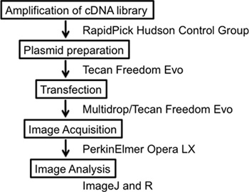 Figure 1. Overall scheme of the experiment. The experiment details a complete high-content screening workflow starting with the amplification and preparation of the cDNA library, transfection of cDNA vectors plus reporter constructs, image acquisition and image analysis using the free open software IMAGEJ.
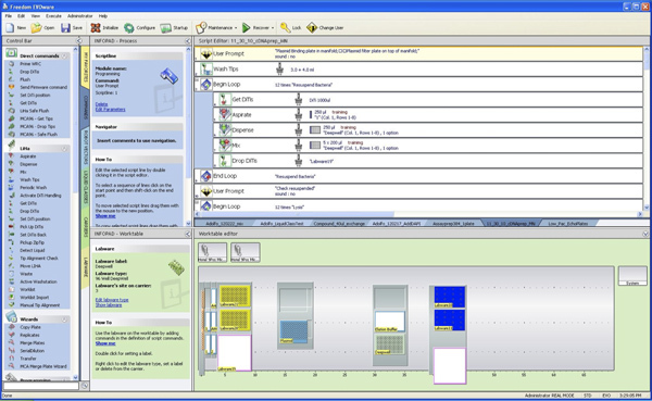 Figure 2. Configuration of the Tecan Deck. (1) On the left-hand side, five 100 ml troughs need to be filled with buffers 1 (40 ml), 2 (40 ml), 3 (50 ml), AW (60 ml) and A4 (100 ml). Trough A4 will need to be re-filled once during the procedure. (2) The vacuum manifold is located on position 14 in this example. (3) The deepwell plate with bacterial pellets is located on position 30, next to the elution buffer trough with 25 ml Elution buffer. (4) Disposable tips for the 8-channel head need to be loaded in the tip racks on the left side and tips for the multichannel head need to be filled on position 40. The Tecan FreedomEvo liquid handler that is used in this experiment is equipped with 500 μl syringes. Click here to view larger figure.
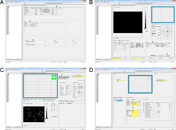 Figure 3. Automation of image acquisition on the Opera LX. A) Select the Configuration tab (1). Activate the Laser lines required for the experiment (2). Select the cameras for image acquisition (3). Select the plate type and objective lens for the experiment (4). B) Select the microscope tab (1). Define the light source and exposure time for exposure 1 (2,3). Focus on one well and take height (4). C) Select the Experiment Definition tab (1). Drag and drop exposure, skewcrop, reference, layout and sublayout files (2). Drag and drop the experiment file (3). D) Select Automatic Experiment (1). Drag and drop experiment file (2). Allocate appropriate barcode (3). Start image acquisition by clicking on the start button (4). Click here to view larger figure.
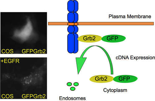 Figure 4. GFP-Grb2 translocation by cDNA expression. GFP-Grb2 relocates from a predominant cytoplasmic localization to endosome-like structures upon overexpression of a transmembrane growth factor receptor and subsequently internalizes to endosomes. On the left, microscopy images of COS M6 cells are shown that were transiently transfected with GFP-Grb2 (top) or GFP-Grb2 plus EGFR (bottom). Co-expression of the EGFR results in relocation of GFP-Grb2 to endosome-like structures.
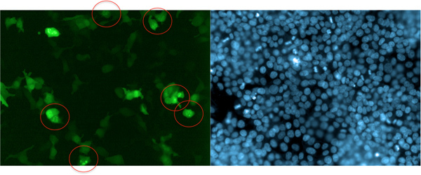 Figure 5. Example of cDNA-induced translocation of GFP-Grb2. The GTPase Dynamin2, which is involved in Grb2-mediated endocytosis, relocates GFP-Grb2 to endosome-like structures (circled). In this experiment, GFP-Grb2 was co-transfected with DNM2 into HEK293T cells. Cells were stained with Hoechst 33342 after 24 hr and images were acquired on the Opera LX. One field of view of the green (GFP) channel and the UV (blue; Hoechst 33342) is displayed.
Discussion
Expression cloning is a powerful tool that has been used in the past to identify novel cellular components such as virus receptors and blood cell antigens12. Here, we describe a method to facilitate the identification of novel putative signal transduction receptors that bind to Grb2.
There are a few critical steps in the protocol.
For automated plasmid preparation it is absolutely essential to have complete resuspension of the bacterial pellet. Sometimes, it is necessary to include a rigorous shaking step or further mixing with pipettes.
Upon addition of solution 2 and 3, complete mixing is essential and we have found that manually inverting the sealed plate is more efficient than the use of an automated shaker. Pipetting should be avoided at this step as it would lead to shearing of the DNA.
In all vacuum steps, one has to ensure that the liquid is completely drained from the plate. Otherwise low yields are to be expected.
Upon elution, it is quite common that eluate drops form at the bottom of the plasmid binding plate. These drops need to be collected in the elution plate, so it is recommended that the plasmid binding plate is lifted carefully and any residual drops at the bottom are carefully transferred to the eluate plate.
During transfection, the time of complex formation is critical. We usually adhere to 20-30 min. Longer times up to 1 hr are fine without reduction in yield, while shorter times are not recommended.
For the microscopy, the choice of magnification is important. On the Opera LX system used here, resolution at 20x is sufficient to get high quality images. If higher resolution images are required, the objective can be changed, but in order to get statistically significant numbers of cells, a higher number of fields and higher acquisition times are required. In general, we aim to get at least 100 cells imaged per well.
The Grb2 translocation assay has been used by other groups to identify small molecule inhibitors of EGFR kinase activation6. In that case, the EGFR is specifically activated with ligand causing recruitment of Grb2 to the plasma membrane. Disruption of this interaction can then be investigated using small molecule compounds. Similarly, it can be envisaged that siRNA screens can be employed to identify endogenous genes involved in EGFR-Grb2 signaling or other Grb2-binding growth factor receptors such as c-KIT or the erythropoietin receptor. Thus, there are multiple potential applications for this technique. An analogous approach could be applied to GFP-tagged reporter systems for other adapter molecules such as Shc, Gab or IRS.
One major advantage of using this cell-based assay in mammalian cells is that it enables the identification of physiologically relevant interactions. The assay is a readout for protein complex formation, but more importantly, the relevant interactions are monitored at the correct sub-cellular site. In this regard, this technique overcomes artifacts from other protein-protein interaction methods such as yeast-two-hybrid or in vitro assays. It should be noted though, that indirect interactions may also result in Grb2 recruitment. Similarly, the transcriptional up-regulation of binding partners may be induced by cDNA expression. To distinguish between these possibilities, it is necessary to perform the appropriate secondary assays to distinguish between direct and indirect binding effects.
In conclusion, the GFP-adapter molecule translocation assay promises high potential for genome-wide screening and drug discovery applications.
Disclosures
No conflicts of interest declared.
Acknowledgments
This work was supported by the Medical Research Council and the Marie-Curie International Reintegration Grant scheme (to JKV).
References
- Sastry L, Cao T, King CR. Multiple Grb2-protein complexes in human cancer cells. Int. J. Cancer. 1997;70:208–213. doi: 10.1002/(sici)1097-0215(19970117)70:2<208::aid-ijc12>3.0.co;2-e. [DOI] [PubMed] [Google Scholar]
- Li S, Couvillon AD, Brasher BB, Van Etten RA. Tyrosine phosphorylation of Grb2 by Bcr/Abl and epidermal growth factor receptor: a novel regulatory mechanism for tyrosine kinase signaling. Embo. J. 2001;20:6793–6804. doi: 10.1093/emboj/20.23.6793. [DOI] [PMC free article] [PubMed] [Google Scholar]
- Bisson N. Selected reaction monitoring mass spectrometry reveals the dynamics of signaling through the GRB2 adaptor. Nat. Biotechnol. 2011;29:653–658. doi: 10.1038/nbt.1905. [DOI] [PubMed] [Google Scholar]
- Ketteler R. The Feynman trajectories: determining the path of a protein using fixed-endpoint assays. J. Biomol. Screen. 2010;15:321–326. doi: 10.1177/1087057109357116. [DOI] [PubMed] [Google Scholar]
- Yamazaki T. Role of Grb2 in EGF-stimulated EGFR internalization. J. Cell. Sci. 2002;115:1791–1802. doi: 10.1242/jcs.115.9.1791. [DOI] [PubMed] [Google Scholar]
- Antczak A. Domain-Based Biosensor Assay to Screen for Epidermal Growth Factor Receptor Modulators. in Live Cells. ASSAY and Drug Development Technologies. 2012;10:24–36. doi: 10.1089/adt.2011.423. [DOI] [PMC free article] [PubMed] [Google Scholar]
- Su J, Batzer A, Sap J. Receptor tyrosine phosphatase R-PTP-alpha is tyrosine-phosphorylated and associated with the adaptor protein Grb2. J. Biol. Chem. 1994;269:18731–18734. [PubMed] [Google Scholar]
- Hertog Jden, Tracy S, Hunter T. Phosphorylation of receptor protein-tyrosine phosphatase alpha on Tyr789, a binding site for the SH3-SH2-SH3 adaptor protein GRB-2 in vivo. Embo. J. 1994;13:3020–3032. doi: 10.1002/j.1460-2075.1994.tb06601.x. [DOI] [PMC free article] [PubMed] [Google Scholar]
- Miki H. Association of Ash/Grb-2 with dynamin through the Src homology 3 domain. J. Biol. Chem. 1994;269:5489–5492. [PubMed] [Google Scholar]
- Seedorf K. Dynamin binds to SH3 domains of phospholipase C gamma and GRB-2. J. Biol. Chem. 1994;269:16009–16014. [PubMed] [Google Scholar]
- Carpenter AE. CellProfiler: image analysis software for identifying and quantifying cell phenotypes. Genome Biol. 2006;7:R100. doi: 10.1186/gb-2006-7-10-r100. [DOI] [PMC free article] [PubMed] [Google Scholar]
- Seed B. Developments in expression cloning. Curr. Opin. Biotechnol. 1995;6:567–573. doi: 10.1016/0958-1669(95)80094-8. [DOI] [PubMed] [Google Scholar]


