

Abstract
The annulus fibrosus (AF) of the disc is a highly nonlinear and anisotropic material that undergoes a complex combination of loads in multiple orientations. The tensile mechanical behavior of annulus fibrous (AF) in the lamellar plane is dominated by collagen fibers and has been accurately modeled using exponential functions. On the other hand, AF mechanics perpendicular to the lamella, in the radial direction, depend on the properties of the ground matrix with little to no fiber contribution. The ground matrix is mainly composed of proteoglycans (PG) which are negatively charged macromolecules that maintain the tissue hydration via osmotic pressure. The mechanical response of the ground matrix can be divided in the contribution of osmotic pressure and an elastic solid part known as extra-fibrillar matrix (EFM). Mechanical properties of the ground matrix have been measured using tensile and confined compression tests. However, EFM mechanics have not been measured directly. The objective of this study was to measure AF nonlinear mechanics of the EFM in tension and compression. To accomplish this, a combination of osmotic swelling and confined compression in disc radial direction, perpendicular to the lamella was used to measure the mechanics of the EFM in tension and compression. For this type of analysis, it was necessary to define a stress-free reference configuration. Thus, a brief analysis on residual stress in the disc and a procedure to estimate the reference configuration are presented. The proposed method was able to predict similar swelling deformations when using different loading protocols and models for the EFM demonstrating its robustness. The stress-stretch curve of the EFM was linear in the range 0.9 < λ3 < 1.3 with an aggregate modulus of 10.18 ± 3.32 kPa; however, a significant non-linearity was observed for compression below 0.8. The contribution of the EFM to the total aggregate modulus of the AF decreased from 70% to 30% for an applied compression of 50% of the initial thickness. The properties obtained in this study are essential for constitutive and finite element models of the AF and disc and can be applied to differentiate between functional degeneration effects such as PG loss and stiffening due to cross-linking.
Keywords: Annulus Fibrosus, Extra-fibrillar Matrix, Confined Compression, Osmotic Swelling, Residual Stress
Introduction
Back pain is a major public health problem which is often related to intervertebral disc degeneration. Under physiological loads, the disc is subjected to a complex combination of loads including bending, torsion and axial compression. This complicated loading environment is supported by the interaction between components of the disc, i.e., annulus fibrosus (AF), nucleous pulposus and the end plates. Understanding the mechanical behavior of the disc is extremely important to design treatment strategies to restore normal function of degenerate discs. The AF has a very specialized structure that undergoes large and multi-directional loading. It is composed of concentric lamellae of collagen fibers embedded in a network of proteoglycans and minor proteins sometimes referred to as ground matrix. The tensile behavior of the AF, parallel to the lamellae, is highly non-linear and has been successfully described using by polynomial and exponential functions (Elliott and Setton 2000, 2001; Wagner and Lotz, 2004; Ambard and Cherblanc, 2009; O’Connell et al., 2009; Eberlein et al., 2001; Klish and Lotz, 1999; Guo et al., 2006). On the other hand, AF mechanics perpendicular to the lamellae, in the radial direction, depends on the properties of the ground matrix with little fiber contribution. The ground matrix is mainly composed of proteoglycans (PGs) which form a network of interconnected negatively charged macromolecules. The amount negative charge in the tissue is quantified by the fixed charge density. PGs create an inbalance of ion concentration between the tissue and the surrounding fluid which results in an increased hydration due to osmotic pressure. Thus, the mechanical response of the ground matrix can be divided in the contribution of osmotic pressure and an elastic solid part known as extra-fibrillar matrix (EFM). The mechanical properties of the ground matrix have been measured either in tension or compression (Perie et al., 2006; O’Connell et al., 2009). However, tension tests in the radial direction may not isolate completely the contribution of fibers due to fiber reorientation in the direction of loading. Additionally, the size of the sample for tension tests span from outer to inner AF, therefore, the measured properties are an average of these heterogeneous regions.
Sophisticated models such as biphasic, triphasic and quadriphasic (Mow et al., 1980; Lai et al., 1991; Huyghe and Janssen, 1997) have been used to model the intervertebral disc (Magnier et al., 2009; Yao and Gu, 2007; Sun and Leong, 2004; Ehlers et al., 2009; Schroeder et al., 2008). Multiphasic mixture models are of particular interest because they describe the time-dependent mechanical behavior of individual structure components and their interactions in a convenient continuous formulation. At equilibrium, these models reduce to simpler elastic formulations. For instance, the triphasic model reduces to the contribution of the solid components of the tissue and osmotic pressure (Ateshian et al., 2004). Similarly, the AF at equilibrium can be modeled as the sum of fibers, extra-fibrillar matrix (EFM) and osmotic pressure (Ehlers et al., 2009; Sun and Leong, 2004). The osmotic effects have been well characterized experimentally for several tissues and the relation between the osmotic pressure, fixed charge density and volumetric deformations is well defined (Overbeek, 1956). Although the mechanics of the fibers and osmotic effects are well understood, the mechanics of the EFM has received little attention. In fact, the mechanical properties of the EFM have not been directly measured and in most studies these properties have been estimated or approximated.
The objective of this study was to measure the mechanics of the EFM of bovine AF in tension and compression. To this end, a combination of osmotic swelling and confined compression were used to isolate the contribution of the fibers, the osmotic pressure, and the EFM. Confined compression was applied perpendicular to the fibers to minimize fiber stretching during the mechanical test. To induce tensile deformations in the EFM, the samples were immersed in saline solutions with several concentrations to produce different levels swelling. Then, mechanical properties of the EFM were measured by applying multiple steps of confined compression to probe the EFM along the transition from tensile to compressive deformations. An analytical method was developed to calculate swelling deformations and stresses in the EFM from a stress-free reference configuration. The results from this study will provide insight to the mechanics of the AF, as well as a robust method to calculate mechanical properties of the EFM that can be used as input parameters for multi-phasic models and structural finite element models.
Analytical Formulation
This section presents the formulation and discusses the assumptions of the model used to describe the mechanics of the AF. First, the relation between AF composition, fixed charge density and osmotic pressure is presented. Then, the contribution of applied and residual stress to the total stress of AF is discussed. Finally, a method to estimate the reference configuration and the swelling stretches and stresses is described.
Osmotic Pressure
The AF is mainly composed of collagen fibers, proteoglycans and water. Proteoglycans are large molecules composed of many glycosaminoglycans attached to a long core protein. Glycosaminoglycans are chains of polysaccharides that in physiological pH and ionic strength present an excess of negatively charged ions (Comper and Laurent, 1978). Due to their large size, proteoglycans are trapped in the network of collagen fibers. Therefore, collagen and PGs form a charged, porous, deformable solid embedded in a solution of water and ions (Urban and Maroudas, 1981). The amount negative charges attached to the solid are quantified by the fixed charge density. At equilibrium, the balance of chemical potentials results in an increase of osmotic pressure (p), which is a function of the fixed charge density and the ionic strength of the surrounding fluid (Overbeek, 1956). Assuming ideal solutions for the interstitial fluid and external solution, the osmotic pressure can be expressed as:
| (2) |
Where R is the universal gas constant, T is the absolute temperature, cfc is the fixed charge density and cb is osmolarity of the surrounding fluid bath.
The osmotic pressure and the external applied forces result in deformation of the solid component of the AF, which in turn alter the fixed charge density (cfc). That change can be quantified by
| (3) |
Where cfc0 and are the fixed charge density and the water content, respectively, at the reference configuration; and J is the ratio between the volume at the deformed and reference configuration. Thus, the reference configuration, usually defined as the configuration where stresses in the EFM are zero, plays an important role in the calculation of the osmotic pressure. In the absence of external loading, the osmotic pressure produces a stretching of the EFM until equilibrium is reached between the osmotic pressure and the induced stresses in EFM. Those stresses induced by the osmotic pressure are commonly known as residual stress. However, osmotic pressure is not the only source of residual stress. The analysis of residual stress in this study is important, since a stress-free reference configuration must be considered to calculate the osmotic pressure and deformations and stresses of the EFM. In the coming section a brief review of potential sources of residual stress in the intervertebral disc is presented.
Residual Stress
Residual stress is the internal stresses present in the tissue after external loads are removed. When the external loads are applied to the tissue additional stress builds up from the already existent residual stress. As described by Lanir (2009), there are several mechanisms at different scales contributing to residual stress. At the micro-level, the interaction between proteoglycans, ions, water and the collagen network, as described above, produce an osmotic pressure that contributes to the total stress of the tissue. The osmotic pressure is present even when no loads are applied to the disc and is considered a major contributor to the residual stress. Some studies have suggested that cell division and deposition of extracellular matrix on an already stressed substrate may also contribute to residual stress at the micro-level (Ateshian et al., 2009; Ateshian and Ricken, 2010). At the meso-level, residual stress comes from the inhomogeneities within the tissues, e.g, the gradient of proteoglycan and collagen content from inner and outer annulus. Residual stress at meso-level has been recently shown by measuring the opening angle after a radial cut in bovine AF rings (Gardner-Mose et al., 2011). This effect is similar to that observed in aortic arteries, where differences in proteoglycan content between the media and the adventia contribute to this component of the residual stress (Choung and Fung, 1986; Azeloglu et al., 2008). At the disc level, residual stress is also generated by the interaction between different substructures (nucleus pulposus, AF, endplates and vertebral bodies). The high proteoglycan content, and therefore fixed charge density, of the nucleus pulposus results in a significant osmotic pressure. The expansion of the nucleus is constrained by the AF, endplates and vertebral bodies. The radial expansion of the nucleus is constrained by the AF through tensile stresses in the circumferential direction (hoop stress) and compression stress in the radial direction. Similarly, the pressure in the nucleus tends to vertically separate the vertebral bodies, which are hold in place by tensile stresses in the AF in the axial direction. All these contributions to the residual stress of the AF create a complex initial state of stresses and strains that must be considered for the accurate description and analysis of disc mechanics.
A stress-free reference configuration must be considered to measure elastic response and properties of the EFM. Due to the orientation and size of the samples used in this study (described below), the samples may be considered free from residual stress caused by meso- and disc-level mechanisms. The contribution of residual stress caused by cell division and deposition of extracellular matrix for the AF has not been characterized experimentally; however, it can be considered as an effect relevant to a remodeling process and hence unlikely to change during mechanical test or alter the outcomes of the analysis in this study. Therefore, osmotic pressure is the major contributor to residual stress. In this study, osmotic pressure and its associated deformation (swelling) are used to induce tensile deformations and stresses in the EFM. The concept of using osmotic swelling as a loading mechanism has been used to measure mechanical properties of other connective tissues (Basser et al., 1998; Narmoneva et al; 2001; Chahine et al., 2004).
The total (applied) Cauchy stresses the tissue (σ) is the addition of the stresses in the EFM (σEFM), the fibers (σfb), and the osmotic pressure
| (4) |
It can be observed that in the absence of applied stresses (σ = 0), the residual stress developed in the solid part of the tissue is equal to the osmotic pressure
| (5) |
The elastic deformations associated to these residual stresses, osmotic swelling, can be calculated through the constitutive equation
| (6) |
Where F is the deformation gradient, E the Lagrangian strain tensor, ΨEFM and Ψfb are the strain energy functions of the EFM and the fibers, respectively. Notice that F, E, J, ΨEFM and Ψfb are calculated from a stress-free reference configuration. In the same way, the fixed charge density and the osmotic pressure (Eqs 2 and 3) are calculated from same the reference configuration. Theoretically, a stress-free reference configuration can be obtained by removing the osmotic effects; e.g., by soaking the sample in a bath with a high salt concentration. However, in pilot studies (not shown) it was very difficult to apply confined compression on the same sample after changing the concentration of NaCl of the bath from 0.15 or 0.06M to 2M because small inhomogeneities in the sample thickness caused unreliable measurements of the subsequent applied stress. Therefore, in this study only one sample per bath concentration was used, i.e., each sample was swollen, prepared and tested in a single bath concentration. A method to calculate the reference configuration and swelling stretches is proposed based on the equilibrium between osmotic pressure, applied stress, and EFM stresses (e.g., Eq. 4).
Reference Configuration
In this section a method to calculate swelling deformation and the reference configuration is presented. As shown above, the osmotic pressure and stresses in EFM are calculated off of the same reference configuration. Therefore, the aim of the method is to calculate a reference configuration (or alternatively swelling stretches) that satisfy equilibrium between the EFM and applied stress and osmotic pressure at each of the applied compression steps. As shown in Eqs (2) and (3), the osmotic pressure is function of cfc0, cb and J. cb is the known salt concentration in the bath and cfc0 can be measured experimentally (explained below). Therefore, the osmotic pressure is only a function of J. The applied Cauchy-stress was calculated by dividing the applied force by sample area. The stresses of the fiber and EFM depend on the deformations calculated from a stress-free reference configuration. If the normal vectors of the faces of a cubic sample are aligned with the principal axis anisotropy, the swelling process can be described by the principal stretches λ1, λ2 and λ3 (Fig. 1). In this case, the volumetric deformations can be expressed as J = λ1λ2λ3. In this study, the EFM was considered as a compressible Mooney-Rivlin material:
| (7) |
Figure 1.

Coordinate system used direction 1, 2, and 3 correspond to disc circumferential, axial and radial orientations, respectively.
And an exponential model was considered for the fibers (Holzapfel et al., 2000):
| (8a) |
| (8b) |
Where I4 and I6 are the squared stretches along the two families of fibers, Sfb is second Piola-Kirchhoff stress tensor, a0 and b0 are unit vectors in the direction of the fibers in the reference configuration. The fiber parameters c4 and c5 can be obtained from tensile tests in the fiber direction. In this study, the collagen fibers are assumed to be contained in the 1–2 plane. This is a reasonable assumption if the samples are carefully dissected to have the cylindrical axis perpendicular to the lamellae.
In the absence of applied stress, for a given set of EFM parameters c1, c2 and c3, it is easy to calculate the free-swelling stretches and that satisfy Eq. (5). To illustrate this process, consider the hypothetical one-dimensional case where λ3 is the only stretch different from 1. For this case, the volumetric deformation becomes J = λ3. From Eqs. (2) and (3), it can be observed that cfc and the osmotic pressure decreases as λ3 increases. Conversely, the stress in the EFM, , increases as a function of λ3. This is true not only for the chosen constitutive equation, but for any constitutive equation that satisfies convexity. Therefore, there is always a stretch, , where the osmotic pressure matches the stress in the EFM (Fig. 2A). A similar procedure is used to obtain the free-swelling stretches in the directions 1 and 2 ( and ). Consequently, the only unknown parameters are the model constants c1, c2 and c3 of the EFM which can be calculated by curve-fitting the equilibrium stresses of a multi-step confined compression test.
Figure 2.

Swelling stretches, in the direction x3, are estimated as the equilibrium between osmotic pressure (p), applied stress (σ3) and EFM stress ( ). A) In the free-swelling condition (in the absence of applied stresses), the EFM will stretch until the stress in the EFM matches the osmotic pressure at . B) If three compression ramps of 10% are applied at each ramp, the EFM stretches are and . The corresponding EFM stress can be calculated from the constitutive equation. The elastic parameters of the model for the EFM must be adjusted to satisfy equilibrium between osmotic pressure, applied stress, and EFM stress. This equilibrium condition can be enforced by minimizing the residue ( ) for all of the applied compression ramps. An iterative process of calculating free-swelling stretches and residues in the equilibrium condition can be performed until the equilibrium condition is satisfied. Then the properties of the EFM and the swelling stretches (or reference configuration) are obtained.
When confined compression is applied perpendicular to fibers after the initial free-swelling, the stretches and are kept constant since there is no lateral expansion. A number of compression stretches ( ), measured from the swollen configuration ( ), are then applied to the sample. Therefore, the stretches of the EFM, measured from the reference configuration, are . The osmotic pressure and the stresses in the EFM can be calculated from Eqs (2) and (6)–(7), respectively. Notice, that since the fibers are in the 1–2 plane, there is no contribution of the fibers to the stress in the direction 3. From Eq. (4), a residue (Δ) between experimental stress measurements and analytical predictions can be expressed as:
| (9) |
Where is experimental applied stress for the nth compression ramp. The parameters c1, c2 and c3 can be obtained by minimizing the residue for all the applied ramps (Eq. 9). This process is illustrated in Fig. 2B. First, for a given selection of parameters c1, c2 and c3, the stretch can be found. If three ramps of 10% of the swollen thickness are applied, EFM stretches in the direction 3 would be and . For each of these stretches, along with and , the residue between the experimental and predicted solid stress can be calculated ( in Fig. 2B). Then, the parameters c1, c2 and c3 can be chosen to minimize the total residue. The stiffness of the EFM can then be easily calculated from the constitutive equation (Eq. 7). During the minimization process, the parameters c1, c2 and c3 must be constrained to result in a positive and convex energy function.
At a first glance, the procedure of estimating the reference configuration and the swelling stretches may seem to depend on the constitutive model used for the EFM. To evaluate this dependence, the following constitutive equation (Holmes and Mow, 1990) was also considered
| (10) |
Where β = α1 + 2α2.
Experimental Studies
Intervertebral discs (n=8) were dissected from bovine tails, wrapped in plastic and frozen at −24°C. On the day of test, a sample parallel to the lamellae was microtomed down to a thickness of 2.5 mm in the radial direction (direction 3, Figure 1). Then, a plug (5 mm in diameter) was harvested using a biopsy punch. The adjacent tissue was saved for glycosaminoglycan measurement. The annulus plug was allowed to swell in a sterile NaCl solution of 0.15M and protease inhibitors for 4 hours. After this swelling, the sample was microtomed again to approximately 1.5 mm in thickness and a 4 mm plug was harvested using a biopsy punch. The thickness was monitored in the confining chamber after applying a preload of 0.01N for a period of 2h. No further swelling was observed after removing the 4mm plug of AF. After the preload, 5 ramps of 10% of the swollen thickness were applied at a rate of 0.005%/s followed by stress relaxation periods of 166, 150, 200, 250 and 330 minutes, respectively. Relaxation times were selected from pilot studies to reach at least 90% of the equilibrium stress relaxation. This amount of applied deformation was expected to produce to deformations in the EFM in the range of ±30%. To test the ability of the proposed method to estimate the swelling deformations for different bath concentrations and loading conditions, a second set of experimental data, consisting of 21 samples from 7 discs (n = 7) were tested in three different bath concentrations (0.06M, 0.15M, 2M). For this second set of tests, three compression ramps of 5% the swollen thickness were applied followed by stress-relaxation periods of 166, 200, 250 minutes.
Tensile properties of the fibers were measured by tension tests in the fiber direction using a protocol reported in a previous study (O’Connell et al., 2009). Briefly, square thin samples were dissected from four discs and microtomed to a thickness of 1.5 mm approximately. Then, a parallel-sided tensile sample aligned with one fiber population was cut using two parallel blades 3mm apart. Final dimensions of the cross-section area were measured using a laser-based device. Each sample was lightly speckle-coated with black enamel paint using an airbrush. Strains were calculated optically using digital images captured every 5 seconds and the commercial software Vic2D (Correlated Solutions Inc., Columbia, SC). The test was performed in a PBS bath mounted on an Instron 5542 (Instron, Norwood, MA). After a 10 min preload of 0.1N, the samples were preconditioned for 20 cycles to 2% strain at a rate of 0.1%/sec. Samples were tested to failure at a strain rate of 0.1%/sec. Parameters c4 and c5 were calculated by curve-fitting the stress-strain data to Eq. (8b). Although the elastic parameters of the fibers are measured before the reference configuration is calculated, a minor effect of this assumption is expected since the swelling of matrix in the direction of the fibers is small compared to other directions due to the much higher stiffness of the fibers.
The glycosaminoglycan content was measured and fixed charged density calculated in the tested sample and the adjacent tissue. To measure the water content in the reference configuration, the sample was immersed in a 2M NaCl solution for 2h to measure wet weight. Then, the sample was immersed back in a 0.15M solution for 2h to remove the salt excess and dried in an oven at 65 °C for 12h before measuring the dry weight. The GAG content was measured using a 1.9 DMMB assay with chondroitin-6-sulfate as the standard. The fixed charge density was calculated from the GAG content as (Chahine et al. 2004):
| (11) |
where cGAG is mg of GAG per ml of water, and MCS and ZCS are the molecular weight and number of charges per CS disaccharide, respectively (ZCS = 2 charges/repeating unit; MCS=513 g/repeating unit).
Once the fixed charge density was calculated, the stresses in the EFM and the swelling stretches were calculated following the procedure presented in the previous section. The stress-stretch curves for the EFM for the second set of experiments were plotted by superimposing the data from the three bath concentrations. From the stress-stretch data of the EFM, the aggregate modulus was calculated as the ratio between changes in stress and stretch. Similarly, the aggregate moduli of the AF (including EFM and osmotic effects) were calculated using the measured stress and applied stretches. The elastic contribution of the EFM to the modulus to the tissue for a give applied stretch was calculated as the ratio between the EFM and tissue aggregate modulus. The effect of the applied stretch on the contribution of the EFM to the tissue aggregate modulus was analyzed using a one way ANOVA. Comparisons of swelling stretches between constitutive models and loading protocols were calculated using a Wilcoxon signed rank test. Significance was defined as p < 0.05.
Results
The GAG content of the tested samples was 4.06±2.29 % of dry weight and the water content was 76.7±5.2 %. The fixed charge density of the tested samples was 0.046±0.009 M. A comparison between tested samples and their adjacent tissue showed no significant difference on the fixed charge density. This indicates that GAG leaching was not significant during the test. The parameters c4 and c5 of the fibers were 2.46 ± 3.06 MPa and 2.11±2.16, respectively. The comparison of swelling stretches for the protocol with three compression ramps of 5% each and three different bath concentrations (0.06M, 0.15M and 2M) showed that the highest deformation was obtained in direction perpendicular to fibers ( ) and the highest swelling stretches were obtained for the 0.06M bath solution (Fig. 3). The swelling stretch in the circumferential directions was very small, as expected, since the circumferential direction has the greatest stiffness due to the fiber orientation. The comparison between Mooney-Rivlin and Holmes-Mow constitutive models for this protocol showed no significant difference between the swelling stretches (Fig. 4). Additionally, the calculated swelling stretches were not different for the two experimental compression protocols (3 ramps of 5% each or 5 ramps of 10% each) (Fig. 5). These observations demonstrate the robustness of the proposed method. The model parameters for both models are shown in Table 1. Notice that the parameter c2 for the Mooney-Rivlin model has a negative value. However, those values were within the limits of convexity of the energy function (Eq. 7). Previous studies on modeling of the mechanics of AF using the same model have also resulted on negative values of c2 (O’Connell et al., 2011; O’Connell et al., 2009).
Figure 3.
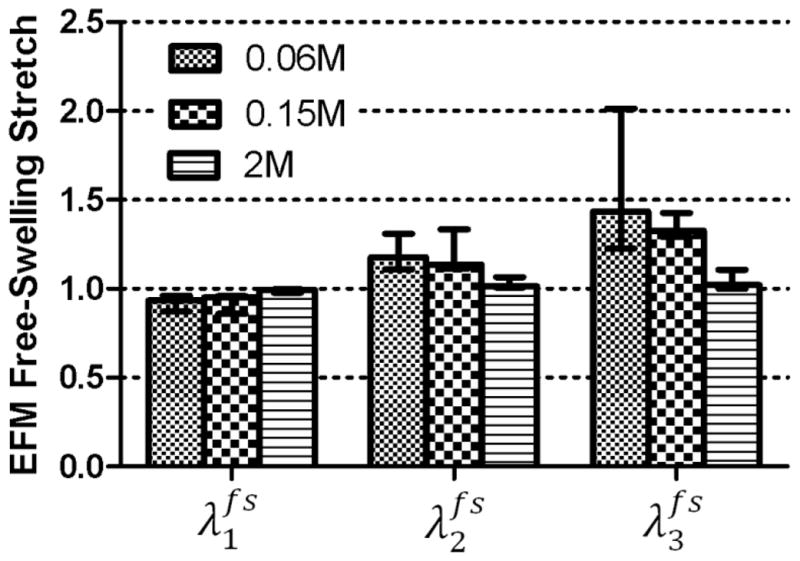
Free-swelling stretch was highest in the direction 3 (radial, p < 0.001) and increased with a decrease in the osmolarity of the bath NaCl solution (p = 0.004).
Figure 4.

Comparison of the Mooney-Rivlin and Holmes-Mow models for the EFM showed no difference between calculated swelling stretches for a 0.15M bath concentration.
Figure 5.

The calculated swelling stretch did not change significantly when two different compression protocols were used: 5 ramps of 10% each and 3 ramps of 5% each (p > 0.05). Both tests were performed in a 0.15M NaCl solution.
Table 1.
Elastic parameters for the Mooney-Rivlin and Holmes-Mow models obtained through the minimization of the residue of the equilibrium condition (Eq. 9). Median and interquartile range.
| Model | Elastic Parameter | ||
|---|---|---|---|
| c1 (MPa) / α0 (MPa) | c2 (MPa) / α1 | c3 (MPa) / α2 | |
| Mooney-Rivlin | 4.04 (3.77–8.39) | −1.82 (−1.09–3.08) | 3.27 (2.64–7.34) |
| Holmes-Mow | 1.82 (1.02–4.71) | 0.46 (0.33–0.64) | 0.44 (0.11–0.61) |
Once the swelling stretches are calculated, and therefore the reference configuration determined, the EFM stretches and stresses were calculated. The stretch-stress curve and the corresponding aggregate modulus for the EFM showed a linear behavior in the stretch range of 0.9–1.3 with an aggregate modulus of 10.18 ± 3.32 kPa (Fig. 6A). A steep increase in the aggregate modulus of the EFM was observed for stretches below 0.8 (Fig. 6B). Comparing the aggregate modulus of EFM and the total aggregate modulus of the AF in the radial direction, it was found that the contribution of the EFM to total modulus of the tissue was 70% for free-swelling at 0.15M bath concentration and decreased to 30% when 50% compression was applied (Fig. 7).
Figure 6.

Mean (interquartile range) of A) stress-stretch curve and B) EFM aggregate modulus for two loading protocols (5 ramps of 10% at 0.15M and 3 ramps of 5% each at 0.15M and 2M) showed similar results (p > 0.05).
Figure 7.
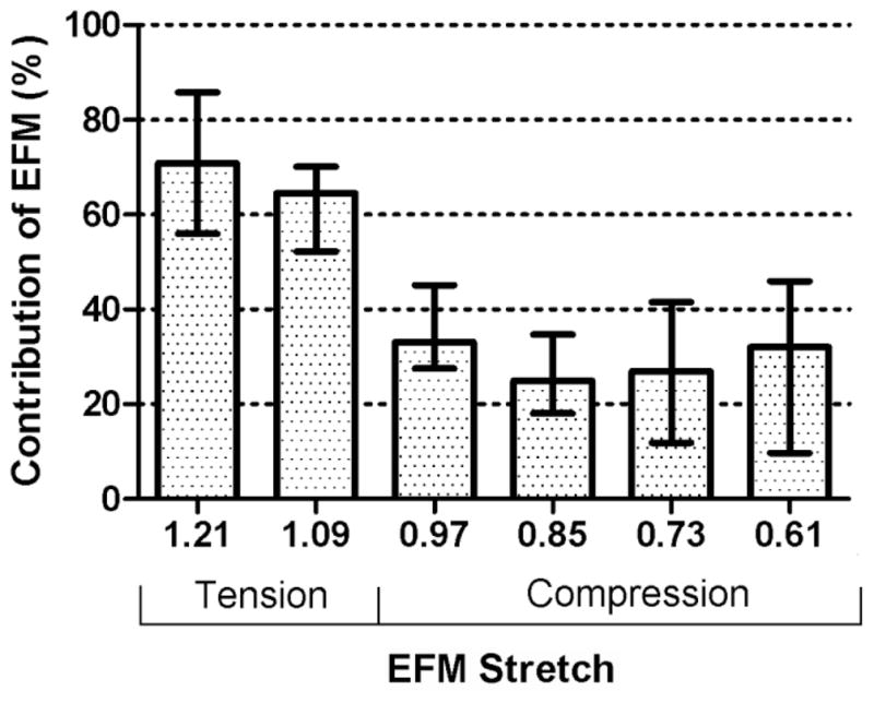
The contribution of the EFM aggregate modulus to the total AF aggregate modulus decreased with compression (p < 0.05).
Discussion
In this study a method to determine the elastic properties of the EFM in tension and compression was presented. This method isolates the osmotic effects from the elastic contribution of the EFM by calculating a stress-free reference configuration. Separating the osmotic and elastic contributions is important for the analysis of degeneration of the intervertebral disc. GAGs loss and protein crosslinking are two processes of the degeneration cascade that alter the mechanics of the disc tissues with opposing effects. In one hand, GAG loss reduces the fixed charge density and consequently impairs the capacity of tissue to support loads through osmotic pressure. On the other hand, protein crosslinking increases the tissue stiffness which may increase the ability to carry loads. The method presented here aims to uncouple these effects to analyze them individually. In addition, multi-phasic models of the AF also consider the osmotic and solid contributions separately. Although the osmotic effects have been well characterized, the contribution of the EFM has received little attention. Using this technique, the mechanics of the EFM can be characterized experimentally.
Here, bovine AF was considered as a model for healthy tissue. The GAG and water content, and therefore the fixed change density, measured in this study were similar to those of mildly-degenerated human outer AF (Iatridis et al., 2007). It was shown that the EFM exhibits a linear behavior in the tension/compression stretch range 1.2 > λ3 > 0.8. A steep increase in the aggregate modulus was observed in the compression range of 0.8 > λ3 (Fig. 6). This observation suggests that for small tension and compression deformations, around the reference configuration, linear models can approximate the mechanics of the EFM. However, these results also showed that for large compressive deformations, the nonlinearity of the EFM must be considered.
It was found that the contribution of the EFM decreases from approximately 70% to 30% when the stretch of the EFM changed from 1.21 to 0.61. These results suggest that the contribution of GAG (e.g., osmotic swelling) is small in tension and increases significantly when the EFM is in compression. Notice that although the aggregate modulus of the EFM is almost constant in the range 0.8 < λ3 < 1.2 and increases when λ3 < 0.8 (Fig. 6b), its relative contribution to the AF modulus reduces. This may seem contradictory; however, the contribution of the EFM decreases because osmotic pressure increases at a much higher rate (i.e., it is more non-linear) than the compressive stress in EFM. The contribution of GAG to the mechanical behavior of AF has been investigated previously (Perie et al., 2006). In that study, significant differences were found for the aggregate between in-situ and free-swelling configuration. A non-significant reduction of approximately 30% was found between free-swelling and GAG digested samples, which is in agreement with contribution of the EFM obtained in this study. Additionally, the differences between in-situ and free-swelling properties emphasize the importance on the selection of a proper reference configuration. A similar analysis on bovine nucleus pulposus showed that the contribution of the solid part is approximately 30% independent of the applied compression (Heneghan and Riches, 2008). In that study, non-linear properties for the solid part of the nucleus pulposus were also reported. However, a compression of 70% of the in-situ thickness was applied and the strains were not calculated from a stress free reference configuration. In human nucleus pulposus a significant correlation between aggregate modulus and GAG content has been reported (Johannessen and Elliott, 2005). In other tissues such as articular cartilage, it has been shown that solid part of the tissue contributes to approximately 40% of the tissue aggregate modulus (Canal-Guterl et al., 2010). However, there are several important differences that must be considered when comparing these results. First, the fixed charge density of articular cartilage is higher than AF. Additionally, in articular cartilage, fibers are oriented in multiple directions including the direction where compression is applied. Therefore, residual stress in the fibers also contributes to the compression stiffness of the solid part of tissue (Nagel and Kelly, 2010).
A method to estimate the stress-free reference configuration was proposed. This method allows estimating the swelling stretches while satisfying the equilibrium between osmotic pressure, applied stress and solid stress for each of the applied compression ramps. A constitutive equation was assumed for the EFM. However, it was shown that the choice of a particular constitutive equation does not alter the results of the predicted swelling stretches and the stretch-stress curve of the solid part of AF. The only purpose of assuming a constitutive equation for the EFM is to provide a continuous, smooth function to connect the applied stress and the free-swelling state, while satisfying the condition that σs = 0 when λ1=λ2=λ3=1. In addition of being insensitive to the constitutive model used for EFM, the method also predicted similar swelling deformations for different loading protocols. Therefore, the method showed an exceptional robustness, perhaps due to equilibrium principle upon which it is based.
The comparison between bath concentrations showed not only that different swelling stretches are obtained, as expected, but also showed that the stretch-stress curves obtained from each bath concentration form a continuous single stretch-stress curve from tension to compression (Fig. 6a). These results suggest that it is equivalent to measure different portions of the stretch-stress curve by using different bath concentrations and small compression ramps or to cover the whole range of deformation with a single bath concentration and applying large compression strains. Another advantage of the proposed method is that the small sample size (4 mm in diameter and 1.5 mm in thickness) will allow testing multiple samples and quantifying heterogeneous mechanical properties (e.g., inner vs. outer AF).
The concept of using osmotic pressure as a loading mechanism to evaluate mechanical properties has been used previously (Basser et al., 1998, Narmoneva et al., 2001; Flahiff et al., 2004; Tepic et al., 1983). An equilibrium condition similar to that of Eq. (4) has been used to calculate the stresses in the collagen network of articular cartilage (Basser et al., 1998); the difference with the present work is that the osmotic loading from calibrated polyethylene glycol solutions was used as external load. In other studies, mechanical properties were calculated in-situ by measuring deformation due to osmotic swelling using optical techniques (Narmoneva et al., 2001; Flahiff et al., 2004). In these studies the reference configuration was obtained after removing the osmotic pressure by soaking the sample in a high salt concentration bath.
There are some limitations associated with this study. First, a small preload was applied to the samples to ensure full contact between the sample and the platen. This preload may cause a small bias during the estimation of the free-swelling configuration. However, due to the magnitude of the measured modulus of the tissue, a small deformation is expected after the application of this preload. Another limitation is that the long testing times are required to reach equilibrium, especially when large compression deformations are applied. However, GAG leaching did not produce a significant change of fixed charged density between adjacent tissue and the sample after the test.
In summary, the mechanical properties of the EFM of the AF were measured experimentally. A method to estimate a stress-free reference configuration was proposed and applied in this analysis. This method showed consistent result when used for different bath concentrations and different test protocols. In the future, the effects of regional variations and degeneration on the properties of EFM of human AF will be addressed. The properties measured in this study are an essential input for multi-phasic models of the disc where all displacements and stresses are calculated from a stress-free configuration.
Acknowledgments
This work was supported with funding from the National Institutes of Health (R01 EB02425) and the Penn Center for Musculoskeletal Disorders.
References
- Ambard D, Cherblanc F. Mechanical behavior of annulus fibrosus: a microstructural model of fibers reorientation. Annals of Biomedical Engineering. 2009;37:2256–2265. doi: 10.1007/s10439-009-9761-7. [DOI] [PubMed] [Google Scholar]
- Ateshian GA, Chahine NO, Basalo IM, Hung CT. The correspondence between equilibrium biphasic and triphasic material properties in mixture models of articular cartilage. Journal of Biomechanics. 2004;37:391–400. doi: 10.1016/s0021-9290(03)00252-5. [DOI] [PMC free article] [PubMed] [Google Scholar]
- Ateshian GA, Costa KD, Azeloglu EU, Morrison B, 3rd, Hung CT. Continuum modeling of biological tissue growth by cell division, and alteration of intracellular osmolytes and extracellular fixed charge density. Journal of Biomechanical Engineering. 2009;131:101001. doi: 10.1115/1.3192138. [DOI] [PMC free article] [PubMed] [Google Scholar]
- Ateshian GA, Ricken T. Multigenerational interstitial growth of biological tissues. Biomechanics and Modeling in Mechanobiology. 2010;9:689–702. doi: 10.1007/s10237-010-0205-y. [DOI] [PMC free article] [PubMed] [Google Scholar]
- Azeloglu EU, Albro MB, Thimmappa VA, Ateshian GA, Costa KD. Heterogeneous transmural proteoglycan distribution provides a mechanism for regulating residual stresses in the aorta. American Journal of Physiology - Heart and Circulatory Physiology. 2008;294:1197–1205. doi: 10.1152/ajpheart.01027.2007. [DOI] [PubMed] [Google Scholar]
- Basser PJ, Schneiderman R, Bank RS, Wachtel E, Maroudas A. Mechanical properties of the collagen network in human articular cartilage as measured by osmotic stress technique. Archives of Biochemistry and Biophysics. 1998;351:207–219. doi: 10.1006/abbi.1997.0507. [DOI] [PubMed] [Google Scholar]
- Canal-Guterl C, Hung CT, Ateshian GA. Electrostatic and non-electrostatic contributions of proteoglycans to the compressive equilibrium modulus of bovine articular cartilage. Journal of Biomechanics. 2010;43:1343–1350. doi: 10.1016/j.jbiomech.2010.01.021. [DOI] [PMC free article] [PubMed] [Google Scholar]
- Chahine NO, Wang CC, Hung CT, Ateshian GA. Anisotropic strain-dependent material properties of bovine articular cartilage in the transitional range from tension to compression. Journal of Biomechanics. 2004;37:1251–1261. doi: 10.1016/j.jbiomech.2003.12.008. [DOI] [PMC free article] [PubMed] [Google Scholar]
- Chuong CJ, Fung YC. On residual stresses in arteries. Journal of Biomechanical Engineering. 1986;108:189–192. doi: 10.1115/1.3138600. [DOI] [PubMed] [Google Scholar]
- Comper WD, Laurent TC. Physiological function of connective tissue polysaccharides. Physiological Reviews. 1978;58:255–315. doi: 10.1152/physrev.1978.58.1.255. [DOI] [PubMed] [Google Scholar]
- Eberlein R, Holzapfel GA, Schulze-Bauer CAJ. An anisotropic model for annulus tissue and enhanced finite element analyses of intact lumbar disc bodies. Computers Methods in Biomechanics and Biomedical Engineering. 2001;4:209–229. [Google Scholar]
- Ehlers W, Karajan N, Markert B. An extended biphasic model for charged hydrated tissues with application to the intervertebral disc. Biomechanics and Modeling in Mechanobiology. 2009;8:233–251. doi: 10.1007/s10237-008-0129-y. [DOI] [PubMed] [Google Scholar]
- Elliott DM, Setton LA. A linear material model for fiber-induced anisotropy of the annulus fibrosus. Journal of Biomechanical Engineering. 2000;122:173–179. doi: 10.1115/1.429639. [DOI] [PubMed] [Google Scholar]
- Elliott DM, Setton LA. Anisotropic and inhomogeneous tensile behavior of the human anulus fibrosus: experimental measurement and material model predictions. Journal of Biomechanical Engineering. 2001;123:256–263. doi: 10.1115/1.1374202. [DOI] [PubMed] [Google Scholar]
- Flahiff CM, Kraus VB, Huebner JL, Setton LA. Cartilage mechanics in the guinea pig model of osteoarthritis studied with an osmotic loading method. OsteoArthritis and Cartilage. 2004;12:383–388. doi: 10.1016/j.joca.2004.01.007. [DOI] [PubMed] [Google Scholar]
- Gardner-Morse MG, Michalek AJ, Iatridis JC. Large residual strains reduce peak stresses in bovine caudal annulus fibrosus. 2011 ORS Annual Meeting; 2011. p. Abstract 0809. [Google Scholar]
- Guo ZY, Peng XQ, Moran B. A composites-based hyperelastic constitutive model for soft tissue with application to the human annulus fibrosus. Journal of the mechanics and physics of solids. 2006;54:1952–1971. [Google Scholar]
- Heneghan P, Riches PE. The strain-dependent osmotic pressure and stiffness of the bovine nucleus pulposus apportioned into ionic and non-ionic contributors. Journal of Biomechanics. 2008;41:2411–2416. doi: 10.1016/j.jbiomech.2008.05.025. [DOI] [PubMed] [Google Scholar]
- Holmes MH, Mow VC. The nonlinear characteristics of soft gels and hydrated connective tissues in ultrafiltration. Journal of Biomechanics. 1990;23:1145–1156. doi: 10.1016/0021-9290(90)90007-p. [DOI] [PubMed] [Google Scholar]
- Holzapfel GA, Gasser TC, Ogden RW. A new constitutive framework for arterial wall mechanics and a comparative study of material models. Journal of Elasticity. 2000;61:1–48. [Google Scholar]
- Huyghe JM, Janssen JD. Quadriphasic mechanics of swelling incompressible porous media. International Journal of Engineering Science. 1997;35:793–802. [Google Scholar]
- Iatridis JC, McLean JJ, O’Brien M, Stokes IAF. Measurements of proteoglycan and water content distribution in human lumbar intervertebral discs. Spine. 2007;32:1493–1497. doi: 10.1097/BRS.0b013e318067dd3f. [DOI] [PMC free article] [PubMed] [Google Scholar]
- Johannessen W, Elliott DM. Effects of degeneration on the biphasic material properties of human nucleus pulposus in confined compression. Spine. 2005;30:E724–9. doi: 10.1097/01.brs.0000192236.92867.15. [DOI] [PubMed] [Google Scholar]
- Lai WM, Hou JS, Mow VC. A triphasic theory for the swelling and deformation behaviors of articular cartilage. Journal of Biomechanical Engineering. 1991;113:245–258. doi: 10.1115/1.2894880. [DOI] [PubMed] [Google Scholar]
- Lanir Y. Mechanisms of residual stress in soft tissues. Journal of Biomechanical Engineering. 2009;131:044506. doi: 10.1115/1.3049863. [DOI] [PubMed] [Google Scholar]
- Magnier C, Boiron O, Wendling-Mansuy S, Chabrand P, Deplano V. Nutrient distribution and metabolism in the intervertebral disc in the unloaded state: A parametric study. Journal of Biomechanics. 2009;42:100–108. doi: 10.1016/j.jbiomech.2008.10.034. [DOI] [PubMed] [Google Scholar]
- Mow VC, Kuei SC, Lai WM, Armstrong CG. Biphasic creep and stress relaxation of articular cartilage in compression: Theory and experiments. Journal of Biomechanical Engineering. 1980;102:73–84. doi: 10.1115/1.3138202. [DOI] [PubMed] [Google Scholar]
- Nagel T, Kelly DJ. The Influence of Fiber Orientation on the Equilibrium Properties of Neutral and Charged Biphasic Tissues. Journal of Biomechanical Engineering. 2010;132:114506. doi: 10.1115/1.4002589. [DOI] [PubMed] [Google Scholar]
- Narmoneva DA, Wang JY, Setton LA. A noncontacting method for material property determination for articular cartilage from osmotic loading. Biophysical Journal. 2001;81:3066–3076. doi: 10.1016/S0006-3495(01)75945-0. [DOI] [PMC free article] [PubMed] [Google Scholar]
- O’Connell GD, Guerin HL, Elliott DM. Theoretical and uniaxial experimental evaluation of human annulus fibrosus degeneration. Journal of Biomechanical Engineering. 2009;131:111007. doi: 10.1115/1.3212104. [DOI] [PMC free article] [PubMed] [Google Scholar]
- O’Connell GD, Sen S, Elliott DM. Human annulus fibrosus material properties from biaxial testing and constitutive modeling are altered with degeneration. Biomechanics and Modeling in Mechanobiology. 2011 doi: 10.1007/s10237-011-0328-9. in press. [DOI] [PMC free article] [PubMed] [Google Scholar]
- Overbeek JThG. The Donnan Equilibrium. Progress in Biophysics and Biophysical Chemistry. 1956;6:57–84. [PubMed] [Google Scholar]
- Perie DS, Maclean JJ, Owen JP, Iatridis JC. Correlating material properties with tissue composition in enzymatically digested bovine annulus fibrosus and nucleus pulposus tissue. Annals of Biomedical Engineering. 2006;34:769–777. doi: 10.1007/s10439-006-9091-y. [DOI] [PMC free article] [PubMed] [Google Scholar]
- Schroeder Y, Elliott DM, Wilson W, Baaijens FP, Huyghe JM. Experimental and model determination of human intervertebral disc osmoviscoelasticity. Journal of Orthopaedic Research. 2008;26:1141–1146. doi: 10.1002/jor.20632. [DOI] [PubMed] [Google Scholar]
- Sun DD, Leong KW. A nonlinear hyperelastic mixture theory model for anisotropy, transport, and swelling of annulus fibrosus. Annals of Biomedical Engineering. 2004;32:92–102. doi: 10.1023/b:abme.0000007794.87408.1e. [DOI] [PubMed] [Google Scholar]
- Tepic S, Macirowski T, Mann RW. Mechanical properties of articular cartilage elucidated by osmotic loading and ultrasound. Proceedings of the National Academy of Sciences. 1983;80:3331–3333. doi: 10.1073/pnas.80.11.3331. [DOI] [PMC free article] [PubMed] [Google Scholar]
- Urban JP, Maroudas A. Swelling of the intervertebral disc in vitro. Connective Tissue Research. 1981;9:1–10. doi: 10.3109/03008208109160234. [DOI] [PubMed] [Google Scholar]
- Wagner DR, Lotz JC. Theoretical model and experimental results for the nonlinear elastic behavior of human annulus fibrosus. Journal of Orthopaedic Research. 2004;22:901–909. doi: 10.1016/j.orthres.2003.12.012. [DOI] [PubMed] [Google Scholar]
- Yao H, Gu WY. Three-dimensional inhomogeneous triphasic finite-element analysis of physical signals and solute transport in human intervertebral disc under axial compression. Journal of Biomechanics. 2007;40:2071–2077. doi: 10.1016/j.jbiomech.2006.10.001. [DOI] [PMC free article] [PubMed] [Google Scholar]