Abstract
Objectives
The objective of this study was to assess the reliability of three-dimensional (3D) cephalometric approaches by comparing this method with authenticated traditional two-dimensional (2D) cephalometry in angular cephalometric measurements.
Methods
CT images and lateral cephalometric radiographs of ten patients (five women, five men) were used in this study. Raw CT data of the patients were converted to 3D images with a 3D simulation program (Mimics 9.0, Leuven, Belgium). Lateral cephalometric radiographs were used manually for 2D measurements. The comparisons of the two methods were made using 14 cephalometric angular measurements. The Wilcoxon matched-pairs signed-ranks test (α _ 0.05) was used to determine the difference between the two methods. To assess the intra- and interobserver reproducibility, two sets of recordings made by each observer, in each modality were used. Dahlberg's formula was used to determine the intraobserver reproducibility, and the Wilcoxon matched-pairs signed-rank test (α _ 0.05) was used to assess the interobserver reproducibility.
Results
The method errors of both observers ranged from 0.35° to 0.65°. In addition, there were no significant differences between the measurements of the two observers (P > 0.05). However, comparison of 2D and 3D parameters showed significant differences in U1-NA and U1-SN measurements (P < 0.05).
Conclusions
The 3D angular cephalometric analysis is a fairly reliable method, like the traditional 2D cephalometric analysis. Currently, the 3D system is likely to be more suitable for the diagnosis of cases with complex orthodontic anomalies. However, with the decrease in radiation exposure and costs in the future, 3D cephalometrics can be a suitable alternative method to 2D cephalometry.
Keywords: cephalometric measurements, computed tomography, three-dimensional cephalometry
Introduction
After the advent of radiographic machines in the early 1900s, Broadbent1 first captured the imagination of orthodontic specialists, and cephalometrics quickly became an essential diagnostic tool in orthodontics.2, 3 Moyers et al4 defined cephalometry as a radiographic technique for abstracting the human head into a measurable geometric scheme. In orthodontics, cephalometric radiography is mostly used to describe the morphology and the growth of the facial skeleton, predict growth, plan treatment and evaluate treatment results.5, 6 For these purposes, orthodontists mark specific anatomical landmarks on cephalometric radiographs, and measure various angular and linear variables. However, cephalometric measurements, like all other measurements, involve errors that are classified as “errors of projection” and “errors of identification”.1, 6 Errors of projection are due to the two-dimensional (2D) head film, which causes a shadow of the three-dimensional (3D) object.
The X-ray beams are non-parallel and originate from a very small source, leading to radiographs that are imperfect, with enlargements affected by the distance between the focus, the object and the film.5, 6 Furthermore, rotation of the patient's head in the cephalostat in any plane and misalignment of the cephalostat also causes errors of projection.6 When evaluating patients with mild craniofacial asymmetries, the lateral cephalometric radiography requires symmetry of the anatomical landmarks or structures based on the left and right portions, and, therefore, can be applied only in combination with posteroanterior cephalometry.7 The errors in identifying specific landmarks on the head films are the identification errors, and are considered to be the major source of errors in cephalometrics by many investigators.6, 8 With the development of CT and 3D reconstructions in the 1970s, related procedures in orthodontics have been attempted through several different approaches.9, 10
These techniques can exactly record and represent the size and the shape of the object.9 Nowadays, reduced exposure and cost have enabled orthodontists to request CT images for various procedures, ranging from diagnosis and treatment planning of congenital malformations to localization of impacted and transposed teeth and positioning of dental implants.2, 11 With these benefits, the routine use of CT scans for orthodontic diagnosis might not be very far away.2, 12 With the newly developed CT machines (cone beam CTs (CBCTs)), a full scan of the head can be performed, in a few seconds during which the patient receives an effective dose of only 50 μSv, which equals the total dose of conventional radiographs that are now considered essential for almost every orthodontic patient, such as the lateral cephalogram and the panoramic radiograph, as well as others that serve auxiliary purposes, such as the occlusal radiograph for locating impacted canines.2, 13 Although there are many benefits of 3D cephalometry, there are limited studies in this field. Thus, the aim of this study was to assess the reliability of 3D angular cephalometric approaches by comparing this method with authenticated traditional 2D cephalometry.
Materials and methods
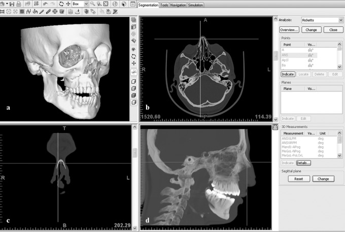
The CT images and lateral cephalometric radiographs of ten patients (five women, five men) were used in this study. Ethical approval for this study was obtained from the ethics committee at Cumhuriyet University, Faculty of Dentistry, and informed consent was obtained from all the study patients. The patients' ages ranged from 17 to 29 years. The CT images were taken for diagnostic purposes before orthognathic surgery. The axial CT images of the patients were taken with a Philips Brilliance CT System (Eindhoven, The Netherlands) at the Cumhuriyet University Medical Faculty, with a tilt of 0°, thickness and table feed of 0.8 mm and original 512×512 matrix with 16 bits. The display fields of view (DFOVs) ranged between 200 mm and 284 mm. The CT scanning was performed at 120 kV, 183 mA and 2.0 s for each of 218–351 slices, depending on the height of the patient's head. The Frankfort plane of the supine patient was observed to be vertical in relation to the horizontal plane. The 2D slices started from the submandibular region and covered the whole head. The CT data were transferred directly from the CT scanner to a personal computer (PC) as raw data sets without the loss of signals. After the CT data was transfered onto the PC, it was converted in to 3D images with a 3D simulation program, Mimics 9.0, (Leuven, Belgium), which is the planning and simulation software for cranio- and maxillofacial surgery. The main features of this software are 3D cephalometry, virtual osteotomy with distraction planning and 3D soft tissue simulation. The same program was used to obtain 3D cephalometric analysis. In the general layout of the program, it is possible to observe the interactive 3D view, axial view, coronal view and sagittal view on the computer screen, and indicate the landmarks easily with the guidance of these views (Figure 1). The cephalometric measurements are preinstalled on the program. First, the cephalometric measurement that is to be assessed is selected and then the landmarks are indicated. Landmarks can be indicated on the 3D view (on bone or soft tissue), which will be automatically visible in the 2D views as well. The 3D image can be rotated to any orientation, and any location starting from the 3D image can be referred to. If a landmark in the 2D view is moved, then it will be updated in any 2D view and 3D view, and vice versa (Figure 2).
Figure 1.
General layout of the Mimics program. (a) interactive 3D view; (b) axial view; (c) coronal view; and (d) sagittal view
Figure 2.
A landmark in the 2D view can be updated in any 2D view and the 3D view, and vice versa
All the lateral cephalometric radiographs were taken in the radiology unit of the orthodontic department. The radiographic equipment used was the Proline PM2002 CC model (Planmeca Oy, Helsinki, Finland). The focus median plane distance was 152 cm with standardized 73 kV, 15 mA for 0.64 s of exposure, and the radiographic film used was Kodak MXG (18 × 24 cm). To obtain 2D measurements, a sheet of transparent acetate was placed over the lateral cephalometric radiographs and the anatomical structures were outlined.
18 cephalometric landmarks were used in this study (Figure 3, Table 1). 14 cephalometric angular measurements, SNA, SNB, ANB, SND, NA-Pog, AB-NPog, Ns-Ba, IMPA, FMIA, Ans-Pns SN, U1-NA, U1-SN, L1-APog and L1-NB, were derived using the landmarks (Figures 4 and 5). Two different orthodontists (FO, RN), each with 4 years of experience, performed both 2D and 3D cephalometric analyses. These orthodontists were experienced and calibrated in the measurements using 3D cephalometry and manual 2D cephalometry. To assess intraobserver reproducibility, two sets of recordings made by each observer in each modality were used. For this purpose, the reference points were removed, marked again and were remeasured by the orthodontists for the second time.
Figure 3.
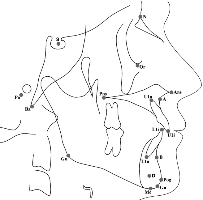
Cephalometric landmarks used in the study
Table 1. Definitions of the cephalometric landmarks.
| Landmark | Definition |
| Sella turcica (S) | Midpoint of pituitary fossa on the skull |
| A point (A) | Position of deepest concavity on the anterior profile of the maxilla |
| B point (B) | Position of deepest concavity on the anterior profile of the mandibular symphysis |
| D point (D) | The geometric centre of the symphysis |
| Gnathion (Gn) | Most anteroinferior point on the symphysis of the chin |
| Menton (Me) | Most inferior point on the symphysis of the mandible |
| Anterior nasal spine (Ans) | The tip of the bony anterior nasal spine, in the median plane |
| Posterior nasal spine (Pns) | Most posterior and middle point on the contour of the bony palate |
| Pogonion (Pog) | The most anterior point of the chin on the mandible in the midline |
| Orbitale (Or) | Midpoint of the bilateral infraorbital margin |
| Porion (Po) | Superior surface of the external auditory meatus |
| Gonion (Go) | Most inferior and posterior points at the right and left angles of the mandible |
| Nasion (N) | Junction of the nasal and frontal bones in the midline |
| Basion (Ba) | Most inferior point of the occipital bone |
| U1i | Tip of the incisal edge of the more anteriorly placed upper central incisor |
| U1a | The point of intersection between the long axis of the more anteriorly positioned upper central incisor and the contour of that tooth's root |
| L1i | The tip of the incisal edge of the more anteriorly placed lower central incisor |
| L1a | The point of intersection between the long axis of the more anteriorly positioned lower central incisor and the contour of that tooth's root |
Figure 4.
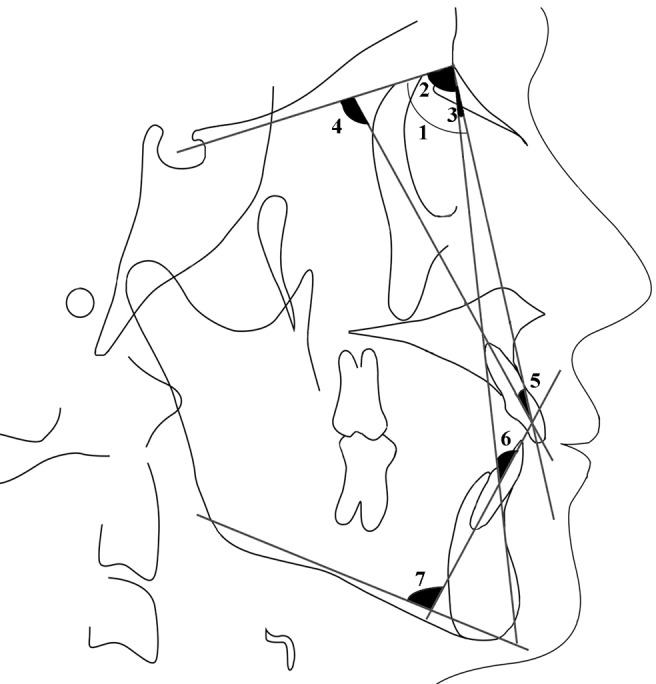
Cephalometric measurements: 1, SNA; 2, SNB; 3, ANB; 4, U1-SN; 5, U1-NA; 6, L1-NB; 7, IMPA (see Table 1 for definitions of the abbreviations)
Figure 5.
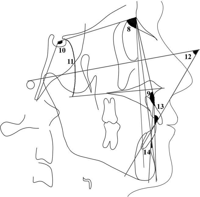
Cephalometric measurements: 8, SND; 9, NA-Pog; 10, Ns-Ba; 11, SN ANS-PNS; 12, FMIA; 13, L1-APog; 14, AB-NPog (see Table 1 for definitions of the abbreviations
The data from this study were analysed using SPSS for Windows, version 13.0 (SPSS Inc., Chicago, IL). Dahlberg's14 formula was used to determine the intraobserver reproducibility. To assess the interobserver reproducibility and to compare the 2D and 3D measurements, the Wilcoxon matched-pairs signed-rank test (α _ 0.05) was used.
Results
The intraobserver reproducibility for the first and the second observer ranged from 0.35° to 0.57° and from 0.42° to 0.65°, respectively. Furthermore, no significant differences were observed between the measurements of the two observers (P > 0.05). As there were no differences between intra- and interobserver measurements, for comparison of the two methods the first measurement of the first author (RN) was used.
A comparison of 2D and 3D cephalometric measurements showed significant differences in U1-NA and U1-SN parameters (P < 0.05). However, the parameters SNA, SNB, ANB, SND, NA-Pog, AB-NPog, Ns-Ba, IMPA, FMIA, SN Ans-Pns, L1-APog and L1-NB did not show any significant differences (P > 0.05). Table 2 shows the detailed value of comparison of the 2D and 3D groups.
Table 2. Detailed value of the comparison of 2D and 3D groups.
| Measurements | 2D | 3D P-value |
| SNA | 78.42° | 78.94° 0.05 NS |
| SNB | 79.07° | 79.43° 0.05 NS |
| ANB | 3.64° | 4.18° 0.05 NS |
| SND | 77.57° | 76.89° 0.05 NS |
| NA-Pog | 172° | 169.3° 0.05 NS |
| AB-NPog | 5.28° | 5.95° 0.05 NS |
| Ns-Ba | 128.85° | 127.18° 0.05 NS |
| IMPA | 76.85° | 77.51° 0.05 NS |
| FMIA | 69.92° | 72.68° 0.05 NS |
| SN Ans-Pns | 9.35° | 11.94° 0.05 NS |
| U1-NA | 24.42° | 27.94° 0.05∗ |
| U1-SN | 101.64° | 90.09° 0.05∗ |
| L1-APog | 19.4° | 18.76° 0.05 NS |
| L1-NB | 18.14° | 17.73° 0.05 NS |
∗Significant at the 0.05% level of confidence
NS, not significant
Discussion
The cephalogram is a standard method used by orthodontists to assess skeletal, dental and soft tissue relationships. This approach, however, is based on 2D views used for the analysis of 3D objects. However, the assessment of 3D structures with 2D methodologies causes information loss and has inherent structural limitations, such as projection and identification errors, which has led orthodontists to search for new techniques.15, 16
The objective of this study was to assess the reliability of 3D cephalometric approaches by comparing this method with authenticated traditional 2D cephalometry in angular cephalometric measurements.
In practice, a high level of accuracy is needed to use 3D image-based measurements, and the accuracy of 3D CT has been investigated and confirmed with various studies.9, 17–20 As we move from traditional 2D cephalometric analysis to new 3D cephalometric techniques, it is often necessary to compare 2D with 3D data.21
Papadopoulos et al3 developed a 3D CT cephalometric analysis for maxillary growth evaluation of sheep fetuses operated on in the uterus, and evaluated the reliability of this analysis by comparing it with a direct cephalometric analysis (2D) on dry skulls. The results of their study showed that there were only 5 (out of 56) variables presenting significant differences between direct cephalometry and 3D CT analysis. Based on these results, 3D CT cephalometric analysis can be considered an accurate and reliable method and could be regarded as equivalent to direct cephalometry.
In this study, the comparison of 2D and 3D cephalometric analyses demonstrated that only the variables U1-NA and U1-SN presented significant differences; the other variables did not present any significant differences between the two methods. Owing to these results it can be assumed that 3D cephalometric analysis could be a fairly reliable method, like direct cephalometric analysis. Also, with these results, it can be assumed that the identification of landmarks, except U1a and U1i, on both the 2D and 3D images were similar.
Stabrun and Danielsen22 showed that, in 75% of their cases, the apex inferior could not be located with confidence by the observers using lateral cephalometric radiographs. However, in the present study, there were no significant differences between the two methods on the measurements IMPA, FMIA, L1-APog and L1-NB, which involves the axis of the lower central incisor. Identification of the apex and incisal edge of the upper and lower incisor is difficult with 2D conventional radiographs because the incisal point of the most prominent incisor is used, although it appears difficult to distinguish between central and lateral incisors on the cephalograms. However, an error can be expected if the lateral incisor is more prominent than the central incisors. Furthermore, because of the poor contrast between the image of the root apex and the surrounding bone, the location of the apex is based more on general knowledge of the length of the tooth and the expected rate of taper perceived from the crown and visible portion of the root than on actually seeing the tip of the root.23
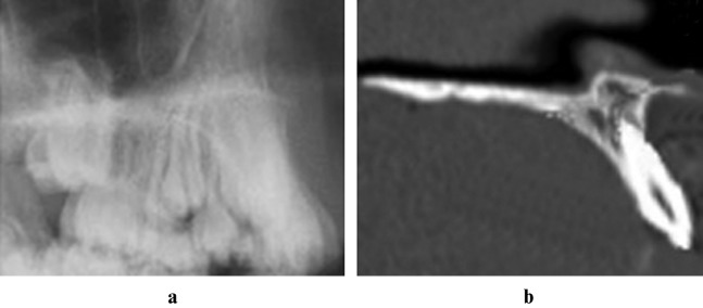
In particular, it is difficult to locate the incisor tooth on the cephalograms of patients with crowded anterior teeth (Figure 6). However, with 3D CT imaging, these landmarks can be easily located and reliable measurements obtained. Also with the 3D technique, we can minimize the errors of projection and identification that cause errors in cephalometric measurement. In this study, there was minimal crowding on the mandibular anterior region in five cases, when all the maxillary anterior regions presented severe crowding. Thus, no significant differences between the IMPA, FMIA, L1-APog and L1-NB measurements were observed. However significant differences between the U1-NA and U1-SN measurements were observed.
Figure 6.
(a) Crowded upper incisors on the lateral cephalometric view. (b) 3D view of crowded upper incisors of the same patient
According to Van Der Meij,7 lateral cephalometric radiography requires symmetry of the anatomical landmarks or structures based in the left and right portions; therefore, when evaluating patients with mild craniofacial asymmetries, it can be applied only in combination with posteroanterior cephalometry. Furthermore, owing to inherent structural limitations of the 2D cephalometric radiographs mentioned earlier, a reliable and accurate evaluation of patients with severe anomalies, such as craniofacial syndromes, is difficult with the 2D method.3, 5, 24, 25 On the general layout of the Mimics program, it is possible to observe an interactive 3D view, axial view, coronal view and sagittal view on the computer screen, and, when the landmarks are indicated on the 3D view (on bone or soft tissue), they will be automatically visible in the 2D views as well. Also, if a landmark is moved in the 2D view, it will be updated in any 2D view and 3D view, and vice versa. With this method, landmarks can be exactly indicated with the guidance of these views. This feature of the program simplifies the work of the clinician, particularly in evaluating patients with mild craniofacial asymmetries or patients with anterior crowding.
The major disadvantages of the 3D cephalometric analysis are high cost and high radiation exposure of CT. As radiation has a cumulative effect on the human body, and most orthodontic patients are children in active growth, any reduction in the exposure to radiation is beneficial.26 In 2007, the International Commission on Radiological Protection (ICRP) included salivary glands, the extrathoracic region and the oral mucosa in the calculation of effective dose, and this resulted in an upward reassessment of fatal cancer risk from oral and maxillofacial radiographic examinations.27 The effective doses for common dental radiographic examinations calculated with the 2007 ICRP guidelines were between 32% and 422% higher than the corresponding doses, as calculated using the older 1990 guidelines.27 In addition, the fatal cancer risk arising from CT and CBCT units calculated with the 2007 ICRP guidelines was between 32% and 422% higher than the corresponding doses, as calculated using the older 1990 guidelines.28 Ludlow and Ivanovic28 recommended dental CBCT as a dose-sparing technique compared with alternative standard medical CT scans for common oral and maxillofacial radiographic imaging tasks. Also, the results of their study showed that the effective dose (ICRP 2007) from a standard dental protocol scan with multidetector CT was 1.5–12.3 times greater than similar medium FOV dental CBCT scans.28 However, Silva et al26 stated that, from a radiation protection point of view, the conventional images still deliver the lowest doses to patients. Thus, in this situation, the risks and benefits to patients should be taken into account.
The 2D cephalometric radiographs have been used successfully for over 70 years in orthodontics, and it appears that this method will survive for many more years. With this study, the authors believe that 3D cephalometric analysis could be a fairly reliable method, like direct cephalometric analysis. Nowadays, owing to the cost of CT scanning of the skull and radiation exposure to the patient, the 3D system is likely to be more suited to those cases with complex maxillofacial deformities, such as asymmetric deformity or cleft palate, and for the diagnosis of patients requiring orthognathic surgery. In the near future, with the decrease in radiation exposure and costs, 3D cephalometrics can be routinely used during orthodontic diagnosis, and might eventually replace many conventional orthodontic records used today.
Acknowledgments
The authors are thankful to Kutsal Tuac (General Manager of 4C Medikal Ltd. Sti.) and the Materialise Group for providing us with the Mimics program and for their technical support. The authors are also grateful to Professor Metin Orhan for his advice and constructive comments during the development of this project.
References
- 1.Broadbent BH. A new x-ray technique and its application to orthodontia. Angle Orthod 1931;51:93–114 [Google Scholar]
- 2.Halazonetis DJ. From 2-dimensional cephalograms to 3-dimensional computed tomography scans. Am J Orthod Dentofacial Orthop 2005;127:627–637 [DOI] [PubMed] [Google Scholar]
- 3.Papadopoulos MA, Jannowitz C, Boettcher P, Henke J, Stolla R, Zeilhofer HF, et al. Three-dimensional fetal cephalometry: an evaluation of the reliability of cephalometric measurements based on three-dimensional CT reconstructions and on dry skulls of sheep fetuses. J Craniomaxillofac Surg 2005;33:229–237 [DOI] [PubMed] [Google Scholar]
- 4.Moyers RE, Bookstein FL, Hunter WS. Analysis of the craniofacial skeleton: cephalometrics. In: Moyers RE (ed). Handbook of orthodontics. Chicago: Year Book Medical, 1988, pp 247–309 [Google Scholar]
- 5.Baumrind S, Frantz RC. The reliability of head film measurements. 1. Landmark identification. Am J Orthod 1971;60:111–127 [DOI] [PubMed] [Google Scholar]
- 6.Adams GL, Gansky SA, Miller A, Harrell WE, Hatcher DC. Comparison between traditional 2-dimensional cephalometry and a 3-dimensional approach on human dry skulls. Am J Orthod Dentofacial Orthop 2004;126:397–409 [DOI] [PubMed] [Google Scholar]
- 7.Van DerMeij A. Reliability and reproducibility of the landmarks of postero anterior cephalometry. Masters Thesis. Aarhus: The Royal Dental College, 1997 [Google Scholar]
- 8.Herman GT, Lie HK. Three-dimensional display of human organs from computed tomograms. Comput Graphics Image Process 1979;9:1 [Google Scholar]
- 9.Xia J, Ip HH, Samman N, Wang D, Kot CS, Yeung RW, et al. Computer-assisted three-dimensional surgical planning and simulation: 3D virtual osteotomy. Int J Oral Maxillofac Surg 2000;29:11–17 [PubMed] [Google Scholar]
- 10.Lagravàre MO, Major PW. Proposed reference point for 3-dimensional cephalometric analysis with cone-beam computerized tomography. Am J Orthod Dentofacial Orthop 2005;128:657–660 [DOI] [PubMed] [Google Scholar]
- 11.Kırzıoğlu Z, Karayılmaz H, Baykal B. Value of computed tomography (CT) in imaging the morbidity of submerged molars: a case report. Eur J Dent 2007;1:246–250 [PMC free article] [PubMed] [Google Scholar]
- 12.Hatcher DC, Aboudara CL. Diagnosis goes digital. Am J Orthod Dentofacial Orthop 2004;125:512–515 [DOI] [PubMed] [Google Scholar]
- 13.Mah JK, Danforth RA, Bumann A, Hatcher D. Radiation absorbed in maxillofacial imaging with a new dental computed tomography device. Oral Surg Oral Med Oral Pathol Oral Radiol Endod 2003;96:508–513 [DOI] [PubMed] [Google Scholar]
- 14.Dahlberg G. Statistical methods for medical and biological students. New York, NY: Interscience Publications, 1940 [Google Scholar]
- 15.Berkowitz S. A multicenter retrospective 3D study of serial complete unilateral cleft lip and palate and complete bilateral cleft lip and palate casts to evaluate treatment. Part 1. The participating institutions and research aims. Cleft Palate Craniofac J 1999;36:413–424 [DOI] [PubMed] [Google Scholar]
- 16.Lagravàre MO, Hansen L, Harzer W, Major PW. Plane orientation for standardization in 3-dimensional cephalometric analysis with computerized tomography imaging. Am J Orthod Dentofacial Orthop 2006;129:601–614 [DOI] [PubMed] [Google Scholar]
- 17.Doruk C, Sökücü O, Biçakçi AA, Yilmaz U, Taş F. Comparison of nasal volume changes during rapid maxillary expansion using acoustic rhinometry and computed tomography. Eur J Orthod 2007;29:251–255 [DOI] [PubMed] [Google Scholar]
- 18.Katsumata A, Fujishita M, Maeda M, Ariji Y, Ariji E, Langlais RP. 3D-CT evaluation of facial asymmetry. Oral Surg Oral Med Oral Pathol Oral Radiol Endod 2005;99:212–220 [DOI] [PubMed] [Google Scholar]
- 19.Matteson SR, Bechtold W, Phillips C. A method for three dimensional image reformation for quantitative cephalometric analysis. J Oral Maxillofac Surg 1989;47:1053–1061 [DOI] [PubMed] [Google Scholar]
- 20.Hildebolt CF, Vannier MW, Knapp RH. Validation study of skull three-dimensional computerized tomography measurements. Am J Phys Anthropol 1990;82:283–294 [DOI] [PubMed] [Google Scholar]
- 21.Cevidanes LHS, Styner MA, Proffit WR. Image analysis and superimposition of 3-dimensional cone-beam computed tomography models. Am J Orthod Dentofacial Orthop 2006;129:611–618 [DOI] [PMC free article] [PubMed] [Google Scholar]
- 22.Stabrun AE, Danielsen K. Precision in cephalometric landmark identification. Eur J Orthod 1982;4:185–196 [DOI] [PubMed] [Google Scholar]
- 23.Chan CK, Tng TH, Hägg U, Cooke MS. Effects of cephalometric landmark validity on incisor angulation. Am J Orthod Dentofacial Orthop 1994;106:487–495 [DOI] [PubMed] [Google Scholar]
- 24.Whyte AM, Hourihan MD, Earley MJ, Sugar A. Radiological assessment of hemifacial microsomia by three-dimensional computed tomography. Dentomaxillofac Radiol 1990;19:119–125 [DOI] [PubMed] [Google Scholar]
- 25.Tyndall DA, Renner JB, Phillips C, Matteson SR. Positional changes of the mandibular condyle assessed by three-dimensional computed tomography. J Oral Maxillofac Surg 1992;50:1164–1172 [DOI] [PubMed] [Google Scholar]
- 26.Silva MA, Wolf U, Heinicke F, Bumann A, Visser H, Hirsch E. Cone-beam computed tomography for routine orthodontic treatment planning: a radiation dose evaluation. Am J Orthod Dentofacial Orthop 2008;133:640.e1–640.e5 [DOI] [PubMed] [Google Scholar]
- 27.Ludlow JB, Davies-Ludlow LE, White SC. Patient risk related to common dental radiographic examinations: the impact of 2007 International Commission on Radiological Protection recommendations regarding dose calculation. J Am Dent Assoc 2008;139:237–243 [DOI] [PubMed] [Google Scholar]
- 28.Ludlow JB, Ivanovic M. Comparative dosimetry of dental CBCT devices and 64-slice CT for oral and maxillofacial radiology. Oral Surg Oral Med Oral Pathol Oral Radiol Endod 2008;106:106–114 [DOI] [PubMed] [Google Scholar]


