

Abstract
An automated increase in the field of view (FOV) for multipurpose cone beam CT (CBCT) by “stitching” (joining) up to three component volumes to yield a larger composite volume must still ensure dimensional stability, especially if the image is to form the basis for a surgical splint. Dimensional stability, image discrepancies and the influence of movement artefacts between exposures were evaluated.
The first consumer installation of the Kodak 9000 three-dimensional (3D) extraoral imaging system with stitching software was used for the evaluation of a human mandible with three endodontic instruments as markers. The distances between several reproducible points were measured directly and the results compared with the values measured on screen. Displacements of the mandible along all axes between exposures as well as angular displacements were conducted to test the capability of the system.
The standard deviations (SD) of the results for the vertical distances varied between 0.212 mm and 0.409 mm (approximately 1–2 voxels; range, 0.6–1.3 mm) and may be considered the systematic error. The SD of the results for the horizontal and diagonal distances varied between 0.195 mm and 0.571 mm (approximately 1–3 voxels; range, 0.6–1.7 mm) if the group with overall horizontal angulations of 10° and a central rotation of 20° was omitted.
In conclusion, the evaluated stitching software is a useful tool to expand the options of combined CBCT with an initial small FOV by allowing a merger of up to three component volumes to yield a larger FOV of about 80 × 80 × 37 mm. The dimensional stability was acceptable when seen in relation to the induced disturbance. Further evaluation of this composite CBCT/digital imaging and communications in medicine system for subsequent splint fabrication may yield promising results.
Keywords: cone beam computed tomography, stitching, dimensional stability
Introduction
Cone beam CT (CBCT) images vary with regard to resolution and field of view (FOV). Surgical specialists generally employ CBCT scanners with a large FOV, while general dentists tend to work with multipurpose X-ray units combining panoramic and three-dimentional (3D) options. These devices often offer high-resolution CBCT images, but their small FOV does not capture the entire jaw. This issue is aggravated when splints for dysgnathia surgery or, even more, drill splints for use in oral implantology are to be fabricated.
Digital imaging and communications in medicine (DICOM) image fusion is a method commonly employed in general medicine to improve diagnostics.1 Although several software solutions exist for creating larger images from single DICOM image files, their usefulness is limited by the need to produce and reproduce reference points for joining or “stitching” images correctly. Applications used in general medicine, therefore, cannot be transferred directly to the dental sphere.
The automated 3D stitching program by Carestream Health (Dental Systems Group, Carestream Health, Inc. Exclusive manufacuturer of KODAK dental system (Stuttgurt, Germany)) recently introduced for the Kodak 9000 3D and Kodak 9000C 3D extraoral imaging systems relieves users of the need to define the required reference points manually. It is sufficient to select the appropriate option from the user menu. The software then automatically combines the volumes into one ready-to-use 3D volume. All the clinician has to do is to correctly position the patient and perform up to three exposures in sequence. The stitching process need not, and indeed cannot, be influenced by the user. The only variable is the movement (displacement) of the patient during and between exposures.
Creating a composite image does not guarantee correct dimensions or dimensional stability. Kodak restricts the use of the current software version to diagnostic purposes only. The stitched 3D volumes, however, must display accurate and consistent dimensions if they are to be used in the fabrication of surgical stents. Dimensional stability, image discrepancies and the influence of movement artefacts between exposures are evaluated in this paper.
Materials and methods
A human mandible was instrumented with K-files (three number 08 files; Kerr, Bioggio, Switzerland) in the distobuccal roots of the left and right second molars (teeth 37 and 47, respectively) as well as in the left central incisor (tooth 41) (Figure 1). The file handles were cut just above crown level and the files were stabilized with composite resin to prevent any mobility. The mandible was mounted on an adjustable table and secured with silicone. Figure 2 shows the mounted mandible, complete with laser reference lines (vertical midline, even if dislocated by rotation, and volume centre). A Kodak 9000 3D extraoral imaging system was upgraded with new erasable programmable read only memory (EPROM) and the newest software versions available (KDIS v. 6.11.6.2 and 3D module v. 2.1) to install the stitching feature. The exposure levels were reduced to the minimum possible (60 kV, 2 mA, 0.2 mm voxel size). The native isotropic voxel size of 0.076 mm is not available in stitching mode because third-party software and post-production installations for splint fabrication cannot handle this resolution at this point. Reference images were taken using the parallel technique and a charged coupled device (CCD) sensor (Kodak RVG 6100) at low exposure levels (70 kV, 4 mA, 0.018 s; Kodak 2200). Seven reference points were defined: the upper ends of each of the files; the lingual foramen; and the lower ends of each file (for control). The reference distances on the radiographs were measured using the software measurement tool in the correctly adjusted layer (Figures 3–6) as well as directly on the mandible using a precision sliding calliper wherever the reference points were accessible. In all, 85 exposures were made, measured and compared. The influence of discrepancies between the three single exposures of each composed volume was examined by identifying the limits tolerated by the software in all three dimensions, as well as vertical and horizontal angulations and rotations. The software generated a stitched 3D volume by comparing the component volumes; however, this process has its limits as the software will not always be able to detect the appropriate reference points. As the discrepancies between the component volumes exceed the processing capacity of the software, error message 11 is displayed and no composite volume is created. The source (component) volumes are, of course, still present and may be used for diagnostic purposes as usual. Radiation exposure is, therefore, limited, as no new exposures need to be made, even if the stitch cannot be calculated.
Figure 1.
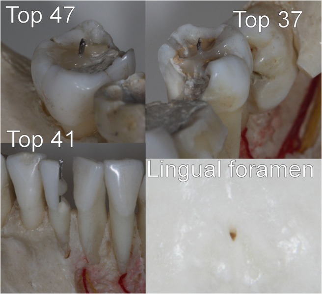
Physically accessible reference points. The lower ends of the files are visible on radiographs only. Examples are omitted owing to common use of intraoral endodontic measurement X-rays
Figure 2.
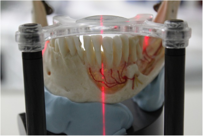
10° central rotation resulting in a projection of the midline laser reference line for patient repositioning on the mesial edge of one canine
Figure 3.

Screenshot with transversely displaced but correctly stitched mandible. The axial (upper left), frontal (lower left) and lateral views (lower right) are added to the pseudo-three-dimensional (3D) view (upper right), showing the displaced cylinders
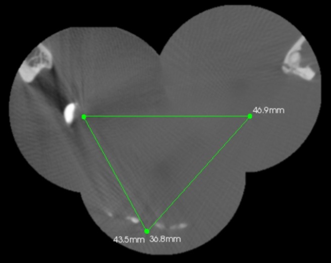
Figure 4.

Diagonal section at the level of the lingual foramen and the upper ends of the molar files (Top 47 to foramen and Top 37 to foramen)
Figure 5.
Top view on angulated and shifted mandible with measurements (Top 37–47, Top 47–41 and Top 37–41) displayed
Figure 6.
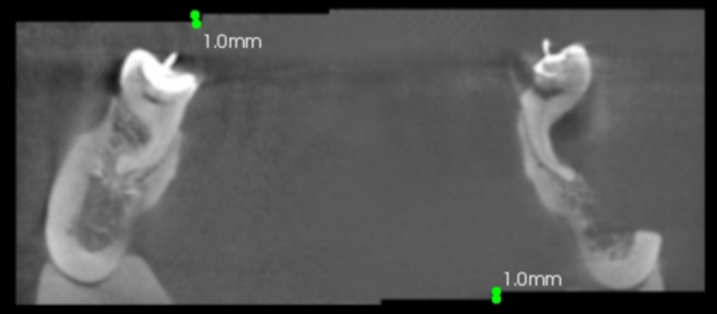
Frontal view of the molar region displaying the vertical discrepancy in the cylinder but correctly stitched bone structures in three component volumes
The vertical distances between the top ends of the files in the incisor and the lingual foramen as well as the lengths of the files were measured and compared to determine the systematic error of the test system. Lengths were measured in 0.1 mm steps; the native size of each voxel was 0.2 mm.
The results were measured with the software provided by the manufacturer on a 19 inch monitor in native resolution (Iiyama AU4831D, 1600 × 1200 pixels; 60 Hz; 200 cd m−2; 300:1 contrast; 25 ms reaction time) (Iiyama, Rohrbach, Germany). The points of interest were located visually and marked by use of a 1000 dpi optical mouse (Logitech, Morges, Switzerland). The current software version does not display the distance during the measurement; rather the measurement result will be displayed once the mouse button has been released. This prevents point locations from being influenced by examiner bias in terms of “desirable” measurements.
Three measurements each were taken by two independent examiners at 1 week intervals. Weighted kappa coefficients were calculated to assess intra- and interobserver agreement for each measurement, and scores were compared with a direct sliding calliper and intraoral sensor measurements using receiver operating characteristic (ROC) analysis to evaluate the influence of human error. Kappa values were calculated to assess intra- and interobserver agreement according to the following criteria: <0.10, no agreement; 0.10–0.40, poor agreement; 0.41–0.60, significant agreement; 0.61–0.80, strong agreement; 0.81–1.00, excellent agreement. Statistics were calculated using SPSS 15.0 for Windows (SPSS Inc.; Chicago, IL).
Results
Intraobserver kappa coefficients calculated for each observer were 0.96 and 0.98, which demonstrated the high level of accuracy of the software and the imaging system. Based on very high intraobserver kappa coefficients suggestive of marked intraobserver agreement, the interobserver kappa coefficient was 0.96.
The averages are presented in Table 1. The primary measurements are twice as fine-grained as the source image resolution. The standard deviation (SD) of the results for the vertical distances, calculated on the top of 41 to foramen, as well as on the file length, varied between 0.212 mm and 0.409 mm (approximately 1–2 voxels; range, 0.6–1.3 mm). The SD of the results for the horizontal and diagonal distances calculated on all other distances in Table 1 varied between 0.195 mm and 0.571 mm (approximately 1–3 voxels; range, 0.6–1.7 mm) if the group with overall horizontal angulations of 10° and a central rotation of 20° was omitted. Accuracy decreases when these groups are included (SD range, 0.212–1.03 mm; range, 0.6–3.1 mm).
Table 1. Average results (mm) and induced displacement for three-dimensional software calculations.
| Top of 37 to 47 | Top of 47 to 41 | Top of 37 to 41 | Top of 47 to foramen | Top of 37 to foramen | Top of 41 to foramen | File in 41 | File in 37 | File in 47 | |
| Control (native and parallel X-ray) | 46.7 | 36.3 | 43.1 | 38.5 | 41.7 | 28.3 | 18.0 | 18 | 16 |
| Stitching unmoved object | 47.1 | 36.5 | 43.2 | 38.8 | 41.7 | 28.7 | 17.7 | 17.3 | 16.6 |
| Horizontal-lateral dislocation (±1.5 mm) | 46.8 | 36.9 | 43.4 | 38.6 | 41.5 | 28.8 | 17.6 | 17.7 | 16.9 |
| Horizontal-anterior-posterior dislocation (±3 mm) | 47.3 | 36.7 | 43.2 | 38.6 | 41.7 | 28.6 | 17.1 | 17.3 | 16.8 |
| Vertical dislocation (±1 mm) | 47.2 | 36.6 | 43.2 | 38.7 | 41.9 | 28.2 | 16.7 | 17.2 | 17 |
| Vertical angulation (±3°) | 46.9 | 36.8 | 43.5 | 38.7 | 41.6 | 28.4 | 16.9 | 17.2 | 17 |
| Horizontal angulation (±5°) | 49.8 | 37 | 44 | 38.7 | 42.1 | 28.2 | 17.3 | 17.4 | 16.6 |
| Central rotation (±5°) | 48.4 | 37 | 44.1 | 39.1 | 42.1 | 28.4 | 17.2 | 17.3 | 16.4 |
| Central rotation (±10°) | 48.4 | 34.1 | 44.4 | 36.5 | 42.3 | 28.5 | 17.5 | 17.3 | 17.2 |
Discussion
The results of this study indicate reliable dimensional stability within the volumes themselves (maximum discrepancy, 2 voxels), which is in agreement with previously published results from other authors.2–4 The stitched volumes, created by the Kodak system evaluated in this report, were acquired by static related rotation axis and subsequently calculated on the images. Horizontal and vertical displacements of up to 6 mm were easily corrected by the software. The angulation mismatch was harder to detect automatically because of the 3D schema of the x, y and z co-ordinate system in DICOM files. A vectorial data encoding system could be an advantage in this respect. Dimensional stability was reliable, with the range and SD value comparable with those of the vertical control group, up to a 10° variation. A central rotation of 20° gave a calculated result, but the deviation was 1.5 mm (2% of the total length). Given that a rotation of this magnitude corresponds to the full distance between the mesial edges of the two canines, this deviation is presumably not clinically relevant (Figure 4). These results may not imply any clinical problems, especially since a surgical splint for implant purposes may still fit and the vertical dimension is not affected by the stitching process at all. Nevertheless, correct, stable positioning of the patient using a silicon bite may improve image quality and avoid errors in creating the composite DICOM volume for further processing. A reference measurement, for example between two fissures of distal molars in situ and on the monitor, may help the operator double check the results.
In conclusion, the evaluated stitching software is a useful tool to expand the options of combined panoramic CBCT with an initial small FOV by allowing a merger of up to three component volumes to yield a larger FOV of about 80 × 80 × 37 mm. The dimensional stability was acceptable when seen in relation to the induced disturbance. Further evaluation of this composite CBCT/DICOM system for subsequent splint fabrication may yield promising results.
References
- 1.Selli C, Caramella D, Giusti S, Conti A, Tognetti A, Mogorovi A, et al. Value of image fusion in the staging of prostatic carcinoma. Radiol Med 2007;112:74–81 [DOI] [PubMed] [Google Scholar]
- 2.Godfrey DJ, Ren L, Yan H, Wu Q, Yoo S, Oldman M, et al. Evaluation of three types of reference image data for external beam radiotherapy target localization using digital tomosynthesis (DTS). Med Phys 2007;34:3374–84 [DOI] [PubMed] [Google Scholar]
- 3.Brown AA, Scarfe WC, Scheetz JP, Silveira AM, Farman AG. Linear accuracy of cone beam CT derived 3D images. Angle Orthod 2009;79:150–7 [DOI] [PubMed] [Google Scholar]
- 4.Grass M, Kohler T, Proksa R. 3D cone-beam CT reconstruction for circular trajectories. Phys Med Biol 2000;45:329–47 [DOI] [PubMed] [Google Scholar]