Abstract
Objectives
The aim of the study was to evaluate the accuracy of linear measurements obtained from reconstructed spiral CT images of human dry skulls in three planes by comparing them with direct skull measurements, and then to compare these with measurements made on photostimulable phosphor cephalograms.
Methods
Using a Siemens Somatom Sensation spiral CT scanner (Munich, Germany), CT images of six human dry skulls were imported into imaging software (Mimics 11.02 Materialise, Leuven, Belgium) and the measurements made were compared to the direct measurements made using a digital calliper (500-171, CD-6C, Mitutoyo, Kawasaki, Japan). The measurements were also compared to those made on frontal and lateral cephalograms taken using a digital cephalostat (Planmeca Oy, Helsinki, Finland). The mean of the 15 linear measurements obtained were compared using the paired Student's t-test.
Results
CT measurements did not show a significant difference from the direct skull measurements (P < 0.05) in all three planes except for two midsagittal measurements in the anteroposterior plane. Cephalometric measurements were comparable to direct skull measurements for midsagittal measurements in the anteroposterior plane, but showed a significant difference when bilateral measurements were considered. Cephalometric measurements also showed a significant difference in the transverse plane from direct measurements and CT measurements; however, they did not display a significant difference between direct skull measurements and CT measurements for most parameters in the vertical plane.
Conclusion
Linear measurements on the spiral CT were comparable to anatomical measurements and were more reliable than cephalometric measurements. Cephalometric measurements were acceptable for midsagittal measurements in the anteroposterior plane, but showed a significant variation from anatomical and CT measurements in most other parameters.
Keywords: spiral computed tomography, software reconstruction, three-dimensional imaging, digital cephalograms
Introduction
Since Broadbent introduced cephalometric radiography in 1931 it has become an indispensable diagnostic and research tool for the orthodontist.1 Cephalometry often determines the way in which orthodontists perceive, diagnose and treat their cases, although two-dimensional (2D) imaging has limitations in the evaluation of three-dimensional (3D) structures as much information is lost. Also, the methodology of cephalometry itself is fraught with both intrinsic and extrinsic factors of error.2–5
In recent years, technological advances have made it possible to acquire 3D data on patients. 3D computer tomography (3D CT) has become extremely popular because it provides a 3D reconstruction of the entire craniofacial skeleton from axial slices. The spiral CT scanner provides adequate image data to create 3D images with reduced scanning time and irradiation compared with conventional CT scanners.6 3D CT rendering techniques have matured rapidly, and several techniques, such as multiplanar reformatting, shaded surface display, volume rendering and maximum intensity projection, have been applied, permitting the evaluation of CT data in all three dimensions.6–8 The widespread use of 3D CT has been found in orthodontics and maxillofacial surgery. While the qualitative information yield has increased, the quantitative accuracy of the information is also important. Several authors have studied the accuracy of 3D CT data as applied to the general craniofacial region.9,10 Studies have also evaluated parameters close to the maxillomandibular structures and established that measurements made are accurate and acceptable.11,12 Linear measurements used in conventional cephalometry have also been evaluated; however, only a few authors have compared linear measurements made on 3D CT-derived cephalograms with conventional cephalograms.13–15
Malocclusion is primarily 3D in nature and 3D CT is of particular benefit in craniofacial deformities with distorted anatomy. Thus, this study sought to evaluate the accuracy of linear measurements made in three planes obtained from 3D CT-derived data reconstructed with 3D software and to compare them with measurements made on conventional cephalograms.
The specific objectives were: to evaluate the accuracy and reliability of linear measurements in three planes obtained from reconstructed 3D CT images of skulls by comparing them with direct measurements of human dry skulls, and to compare these measurements with measurements made on conventional photostimulable phosphor cephalograms.
Materials and methods
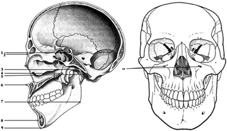
Six human dry skulls were selected from the Department of Anatomy, Sri Ramachandra Medical University. The skulls were not identified by age, gender or ethnic group. All the skulls had adequate teeth, in order to ensure a fixed vertical dimension. Ten landmarks were identified for this study (Figure 1).
Figure 1.
Landmarks on skull. (1) Sella: the center of the base of the hypophyseal fossa. (2) Nasion: the most anterior point of the fronto nasal suture in the median plane when viewed sagitally. (3) Condylion: the midpoint on the superior surface of the condyle (bilateral). (4) PNS (posterior nasal spine): the posterior spine of the palatine bone constituting the hard palate. (5) Basion: the lowermost point on the anterior margin of the foramen magnum. (6) ANS (anterior nasal spine): the anterior tip of the sharp bony process of the maxilla at the lower margin of the anterior nasal opening. (7) Gonion: point midway along the curvature of angle of mandible between inferior border of body and posterior border of body and posterior border of ramus of mandible viewed sagittally (bilateral). (8) Pogonion: the anterior most point on the contour of the chin viewed sagitally. (9) Menton: lowest mid point on the symphyseal outline of the chin viewed frontally and sagittally. (10) Infraorbital foramen: superior margin (bilateral).
Using an adhesive Fevikwik (Pidilite Industries Ltd, Mumbai, India) 2 mm diameter metal spheres (ball bearings) were fixed at all the above mentioned sites except the sella (Figure 2). The condyle was positioned in the glenoid fossa and fused with adhesive, and the mandible was stabilized to the skull with adhesive tape.
Figure 2.
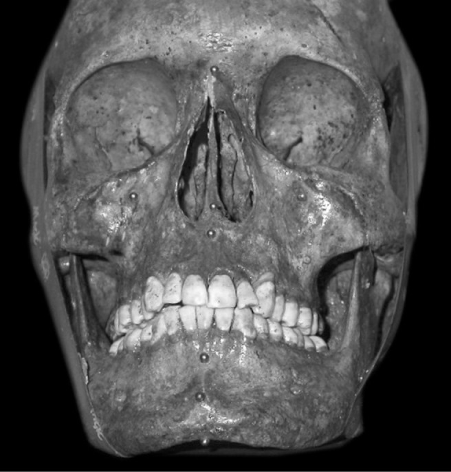
Metal spheres on skull
15 linear measurements were made between the anatomical sites in three planes (Figure 3). Of these, seven measurements were made in the anteroposterior plane (Z-axis or XZ plane). Three measurements were made in the transverse plane (X-axis or XY plane) and five measurements were made in the vertical plane (Y-axis or YZ plane) (Table 1).
Figure 3.
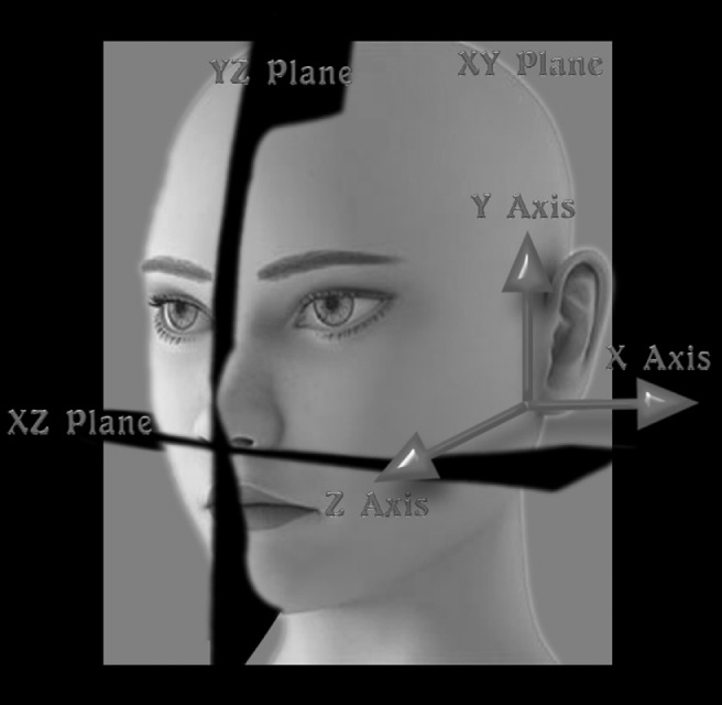
Right-handed XYZ co-ordinate systems
Table 1. Linear measurements in three dimensions.
| Z-axis (anteroposterior) | |
| P1 | Sella to nasion |
| P2 | Basion to nasion |
| P3 | Anterior nasal spine to posterior nasal spine |
| P4 | Condylion to pogonion (right) |
| P5 | Condylion to pogonion (left) |
| P6 | Gonion to pogonion (right) |
| P7 | Gonion to pogonion (left) |
| X-axis (transverse) | |
| P8 | Infraorbital foramen to infraorbital foramen |
| P9 | Condylion to condylion |
| P10 | Gonion to gonion |
| Y-axis (vertical) | |
| P11 | Condylion to gonion(right) |
| P12 | Condylion to gonion(left) |
| P13 | Nasion to menton |
| P14 | Anterior nasal spine to menton |
| P15 | Nasion to anterior nasal spine |
Direct skull measurements (M1)
Direct measurements on the skull were made with a high precision digital calliper. Each measurement of the anatomical site was measured three times by the same operator and the mean was taken. Three sagittal measurements P1 sella to nasion (S-N), P2 basion to nasion (Ba-N) and P3 anterior nasal spine to posterior nasal spine (ANS-PNS) were taken by sectioning the skull through the midsagittal plane using a bone cutting saw (Figure 4).
Figure 4.
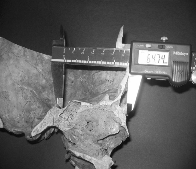
Measurement of sectioned skull with digital callipers
Acquisition of cephalometric data (M2)
Digital cephalometric radiographs were taken using a digital cephalostat (Planmeca Oy, Helsinki, Finland). The source to midsagittal plane distance was maintained at 1.5 m. The detector was placed 15 cm from the midsagittal plane. Exposure settings were 72 kVp, 10 mA with an exposure time of 1 s.
For the lateral cephalograms the skull was stabilized by two ear rods inserted into the external auditory meati and positioned with the Frankfurt plane parallel to the floor, the sagittal plane perpendicular to the X-ray beam and the right side closest to the detector. The central ray was directed at the left external auditory meatus.
For posteroanterior cephalograms the skull was stabilized by two ear rods inserted into the external auditory meati and positioned with the Frankfurt plane parallel to the floor and sagittal plane parallel to the X-ray beam with the facial bones closest to the detector. The central ray was directed midway between the external auditory meati at the level of the external nuchal line.
In order to position the Frankfurt horizontal plane parallel to the floor the skull was further stabilized using adhesive tape running from the posterior part of the skull to the machine.
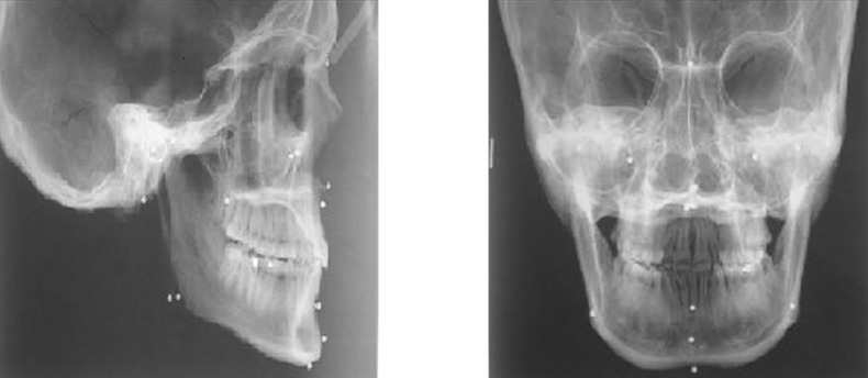
After making the lateral and posteroanterior cephalograms the images were imported into Adobe Photoshop software, Version 7.0 (Adobe, Santa Clara, CA) and the size was standardized at 300 mm × 240 mm.16 The print out was on 8 × 10 inch photographic paper (Figure 5).
Figure 5.
Digital cephalograms
Five measurements (P8–P12) were made on the digital posteroanterior cephalogram, that is, infraorbital foramen to infraorbital foramen (Iof-Iof), condylion to condylion (Co-Co), gonion to gonion (Go-Go), condylion to gonion (Right) (Co-Goright), condylion to gonion (Left) (Co-Goleft). The remaining measurements were made on the lateral cephalogram.
These measurements were made directly on the print out with a high precision digital calliper (Mitutoyo Digimatic CD-6, No.500-171 Mitutoyo Corp, Kawasaki, Japan) with a resolution of 0.01 mm. All parameters were measured three times by the same operator and the mean was taken. Magnification error was accounted for with the help of a 45 mm scale used when taking the radiographs.
Collection of CT data (M3)
All scans were performed on a spiral 64 slice CT scanner (Siemens Somatom Sensation, Munich, Germany). The skulls were placed in the gantry with the head placed in the supine position propped up with headrests, with the Frankfurt horizontal plane perpendicular to the gantry. The gantry tilt was 0°. Each skull was scanned using 1 mm thick slices with the following parameters: 120 kVp, 380 mA, 1 s rotation time and 0.8 pitch. After the image acquisition, the CT data were transferred to digital imaging and communications in medicine (DICOM) format.
The acquired CT data were imported into 3D imaging software (Mimics 11.02 Materialise, Leuven, Belgium) and 3D reconstruction of the virtual image was done. The 15 parameters mentioned previously were measured by the same operator. Each parameter was measured three times and the average was taken (Figure 6).
Figure 6.
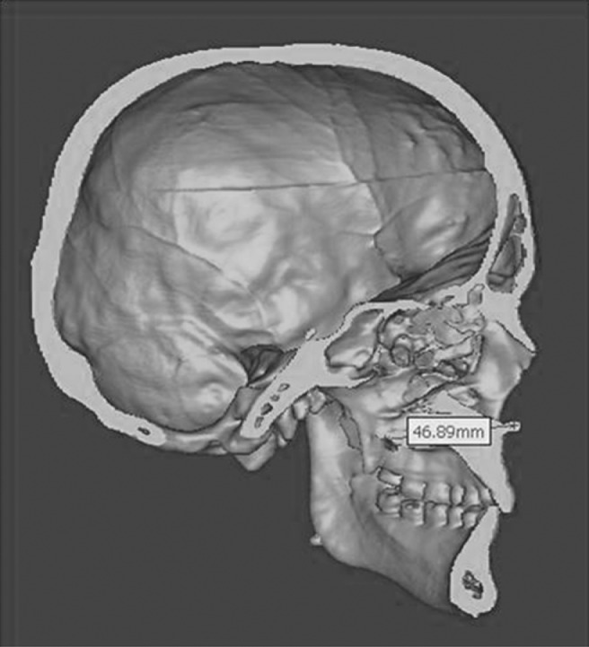
Measurement on three-dimensional virtual image
The above three methods used were designated M1, M2, M3, respectively.
Statistical analysis
A standard statistical software package (SPSS version 12.0, Chicago, IL) was used for the data analysis. The data corresponded to mean ± standard deviation (SD) of 15 measurements made on 6 human dry skulls. The direct measurements were statistically compared with those obtained from the CT images and cephalograms using the paired Student's t-test (P ≤ 0.05). The mean absolute difference between the various modalities and the mean percentage difference was also calculated.
Results
In all three planes, X, Y and Z-axis, there was no statistically significant difference between digital calliper measurement (M1) and CT scan measurements (M3) except for the two parameters in the Z-axis which were P1 (S-N) and P2 (Ba-N) (Table 2).
Table 2. Comparison of mean and standard deviation between 3 modalities of measurement made of 15 variables.
| Axis | Variable | M1 | M2 | M3 | Significance (P ≤ 0.05) |
| Z-axis | P1 | 67.33 ± 2.23 | 68.33 ± 2.34 | 68.76 ± 2.95 | M1 vs M3 (0.04) |
| P2 | 101.44 ± 1.72 | 101.86 ± 2.84 | 102.99 ± 1.48 | M1 vs M3 (0.02) | |
| P3 | 51.64 ± 2.21 | 51.59 ± 1.41 | 52.23 ± 2.90 | ||
| P4 | 114.92 ± 4.30 | 105.75 ± 3.81 | 115.26 ± 4.04 | M1 vs M2 (0.0001); M2 vs M3 (0.0001) | |
| P5 | 114.39 ± 5.88 | 105.44 ± 4.13 | 114.11 ± 6.12 | M1 vs M2 (0.005); M2 vs M3 (0.005) | |
| P6 | 84.83 ± 2.27 | 73.31 ± 3.72 | 84.45 ± 2.45 | M1 vs M2 (0.0001); M2 vs M3 (0.0001) | |
| P7 | 84.55 ± 2.20 | 73.87 ± 5.28 | 85.00 ± 2. 15 | M1 vs M2 (0.003); M2 vs M3 (0.001) | |
| X-axis | P8 | 54.01 ± 3.25 | 55.56 ± 3.40 | 53.75 ± 3.49 | M1 vs M2 (0.003); M2 vs M3 (0.001) |
| P9 | 91.09 ± 5.60 | 96.82 ± 6.21 | 91.81 ± 5.80 | M1 vs M2 (0.0001); M2 vs M3 (0.0001) | |
| P10 | 84.58 ± 7.29 | 90.25 ± 7.93 | 84.58 ± 6.75 | M1 vs M2 (0.0001); M2 vs M3 (0.0001) | |
| Y-axis | P11 | 58.93 ± 4.52 | 61.09 ± 3.37 | 59.46 ± 4.59 | M1 vs M2 (0.03) |
| P12 | 57.62 ± 5.31 | 59.83 ± 4.46 | 57.63 ± 5.48 | M1 vs M2 (0.004); M2 vs M3 (0.01) | |
| P13 | 104.15 ± 3.70 | 103.02 ± 4.77 | 104.14 ± 3.58 | ||
| P14 | 58.86 ± 4.68 | 58.15 ± 5.91 | 59.05 ± 5.49 | ||
| P15 | 45.91 ± 3.17 | 45.71 ± 3.84 | 46.12 ± 3.35 |
M1, direct skill measurements; M2, digital cephalogram; M3, spiral CT
All parameters showed a mean percentage difference of less than 1% except for P1, P2 and P3 (ANS-PNS) (Table 3).
Table 3. Comparison of mean percent difference between M1 and M2 vs M1 and M3.
| Axis Variable | M1&M2 | M1&M3 | P-value < 0.05 | |
| Z-axis | P1 | −1.50 ± 2.42 | −2.10 ± 1.92 | |
| P2 | −0.42 ± 2.65 | −1.54 ± 1.17 | ||
| P3 | −0.05 ± 4.83 | −1.13 ± 3.13 | ||
| P4 | 7.97 ± 1.59 | −0.31 ± 1.09 | 0.0001 | |
| P5 | 7.72 ± 3.84 | 0.25 ± 1.36 | 0.004 | |
| P6 | 13.61 ± 2.79 | 0.45 ± 1.31 | 0.0001 | |
| P7 | 12.63 ± 5.94 | −0.54 ± 1.32 | 0.001 | |
| X-axis | P8 | −2.87 ± 1.28 | 0.51 ± 0.77 | 0.001 |
| P9 | −6.28 ± 1.34 | −0.78 ± 1.02 | 0.0001 | |
| P10 | −6.70 ± 0.84 | −0.05 ± 0.71 | 0.0001 | |
| Y-axis | P11 | −3.82 ± 2.97 | −0.91 ± 1.46 | |
| P12 | −3.98 ± 2.04 | 0.004 ± 0.82 | 0.01 | |
| P13 | 1.04 ± 4.12 | 0.01 ± 0.27 | ||
| P14 | 1.33 ± 3.48 | −0.23 ± 1.52 | ||
| P15 | 0.28 ± 7.43 | −0.44 ± 1.15 | ||
For cephalometry, in the Z-axis there was a significant difference between the direct calliper measurement (M1) and cephalometric measurements (M2) in four out of the seven parameters. There was a significant difference between M2 and M3 in the same four parameters, that is, P4–P7 (Table 2). The mean percentage difference was minimal for three parameters, P1, P2 and P3; however, in the other four the mean percentage difference was large ranging from 7.72 ± 3.84 up to a maximum of 13.61 ± 2.79 (Table 3).
There was a significant difference between M2 and M3 when mean percentage difference was considered in four parameters, that is, P4–P7 (Table 3).
In the X-axis there was a significant difference between both M1 and M2 (P8–P10) and M2 and M3 in all three parameters (Table 2).
There was a significant difference between M2 and M3 when mean percentage difference was considered in all three parameters (Table 3).
In the Y-axis there was a statistically significant difference between M1 and M2 in only two out of five parameters (P11 and P12). There was a statistically significant difference between M2 and M3 in one (P12) out of the five parameters (Table 2). The mean percentage difference between M1 and M2 ranged from 0.28% to 3.98% (Table 3). There was a significant difference in mean percentage difference between M2 and M3 in only one parameter (Table 3).
Discussion
Malocclusion and facial deformity are 3D in nature and this has been appreciated much better in the last two decades with the evolution of 3D imaging. Craniofacial imaging has benefited from the more frequent use of the spiral multislice CT technology, which has been applied in 3D treatment planning, 3D simulation and pre- and post-treatment assessment of dentoskeletal relationships in orthodontics and associated specialties.
While qualitative assessment has improved because of 3D imaging, CT has also been used for a wide variety of quantitative measurements on patients. Linear measurements have been performed in, for example, the cranial vault, brain, orbits and spinal canal.9,10 In the field of dentistry, the accuracy of linear measurements obtained from CT scans have also been evaluated. In orthodontics and maxillofacial surgery, exact measurement is the key element, particularly in cases of complex craniofacial disorders. Although the accuracy of linear measurements obtained from CT scans has been studied, few studies have confined themselves to the maxillomandibular region12,13 and few studies have evaluated measurements, normally done on cephalograms, and compared them to conventional cephalometric measurements.14,15 In addition, no study has evaluated the accuracy of linear measurements in three planes.
In the present study, the CT measurements were larger than direct skull measurements in 10 out of 15 parameters. CT scan measurements showed no statistically significant difference between anatomical measurements in all three planes. The exception to this was two measurements P1 (sella-nasion) and P2 (basion- nasion) in the Z-axis. The mean percentage error for these 2 measurements was 2.10 ± 1.92 and 1.54 ± 1.17. This is probably clinically insignificant because some authors have suggested that a difference of up to 5% is clinically acceptable.9 The mean percentage difference was more than 1% in only P1, P2 and P3, which were all midsagittal measurements in the Z-axis.
While it is not clear why measurements in the Z-axis should be less accurate than others a perusal of literature shows that in 3D renderings of reformatted CT data the 3D simulation is viewed in a conventional 2D format.6 There are two main geometrical strategies for measuring scanned objects in 3D, that is, orthogonal measurements and triangulation; the former is used in CT scans. The X and Y dimensions are measured directly on the slice surface and the Z dimension is measured by tallying the number of slices in the area of interest.
Periago et al13 while measuring CBCT measurements using a Dolphin Imaging System, found that many linear measurements showed statistically significant difference from anatomical dimensions. They found that bilateral measurements were significantly more accurate than midsagittal measurements. This was also similar to the findings in the present study where CT more faithfully represented bilateral structures than midsagittal measurements. However, the authors' contention was that the variation exhibited by CBCT measurements though statistically significant was clinically acceptable.13
Despite the diagnostic benefits, the application of 3D CT to mild dentofacial deformity is limited by economic and logistic considerations. There are also concerns about the increased ionizing radiation dose relative to standard radiographic assessment. Connor et al17 demonstrated that by using an estimated effective dose slightly greater than for radiographs it was possible to achieve accuracy of less than 2 mm for almost all skull landmarks with an interrater precision similar to a high-dose protocol.
Recently CBCT has become more popular than spiral CT for various reasons such as submillimeter spatial resolution, less radiation dosage and shorter time. Thus CT data with low radiation dosage will soon be accessible and clinically acceptable for routine dentofacial deformities. Kobayashi et al8 compared the measurement accuracy of conventional spiral CT and CBCT and found that CBCT was more accurate than spiral CT. In the present study spiral CT was used due to the lack of availability of CBCT and it was found that the accuracy was comparable to anatomical measurements except in 2 out of 15 measurements and even this difference was probably clinically acceptable.
This study also attempted to compare the differences in linear measurements between 3D CT measurements and 2D measurements made on cephalometric radiographs. In the Z-axis lateral cephalometric measurements showed no significant difference to direct skull measurements made on midsagittal structures. However, the variation was vast for bilateral measurements made away from the midsagittal plane. The condylion to pogonion (Co-Pog) distances (P4 and P5) and the gonion to pogonion (Go-Pog) (P6 and P7) distances measured showed a large variation (average of 8% and 13% respectively) from the true dimensions.
This is clinically relevant because these measures are conventionally used to evaluate the size of the mandible. This highlights the conceptual limitations of cephalometric radiography where 3D structures are projected on a 2D image.
Kumar et al14 compared cephalometric measurements from synthesized CBCT lateral cephalograms using orthogonal and perspective projections with those from conventional cephalometric radiographs of dry skulls, found that orthogonal CBCT projections provided greater accuracy of measurement, for midsagittal plane dimensions, than perspective CBCT or conventional cephalometric images. This is in contrast to the findings of the present study in which conventional cephalometry more faithfully represented midsagittal measurements as compared to CT measurements.
All three transverse measurements (P8, P9 and P10) made on posteroanterior cephalograms showed a significant difference from direct skull measurements and CT measurements. The average variation from anatomical measurements ranged from 2% to 6%.
In the vertical plane only two out of five cephalometric parameters (P11 and P12) showed statistically significant variation as compared to anatomical measurements and only one cephalometric parameter (P12) showed significant variation from CT measurements. The variation from anatomical measurements was also less when compared to measurements made in the transverse and anteroposterior plane and ranged from 0.28% to 3.98%.
Thus, measurements made on conventional cephalograms quite faithfully represented anatomical measurements when considering midsagittal measurements made in the Z-axis. They were also acceptable for most parameters in the Y-axis. However, they showed significant difference when considering bilateral measurements in the Z-axis and measurements in the X-axis.
Several cephalometric measurements did not represent the anatomical truth and this is in spite of magnification corrections being made. Most clinicians do not consider magnification error in lateral cephalograms and magnification is said to range from 7% to 12% depending on the instrument.5 In this study the magnification of the lateral cephalograms was 8.8% and the magnification of posteroanterior cephalograms was negligible, that is, only 0.6% as calculated.
Magnification in frontal projections are a more difficult problem because the enlargement factors are much more complicated due to the fact that the landmarks used for interpretation are located in different coronal planes and, therefore, at varying distances from the source and detector surface.18
Cephalometric measurements are subject to various sources of error and need to be interpreted with caution. Moshiri et al15 who compared the accuracy of linear measurements made on photostimulable phosphor cephalograms with three methods for simulating lateral cephalograms with CBCT and found that conventional lateral cephalograms showed the least accuracy. Hilgers et al11 compared CBCT measurements of the temperomandibular joint and associated structures with conventional cephalometric radiography and found that CBCT proved to be accurate, whereas, a good number of cephalometric measurements were statistically significant from the actual anatomical measurement.11
In conclusion, the measurements obtained from spiral CT images were comparable to direct skull measurements in all three planes and were far more reliable than cephalometric measurements, which showed significant variation from actual anatomical measurements in most parameters. Therefore, it would be desirable for orthodontic diagnosis and treatment planning to be based on 3D CT scans rather than on conventional cephalograms especially when decisions depend on accurate linear measurements.
However, it must be considered that the accuracy of CT data obtained from patients may be affected by reduction in image quality due to soft-tissue attenuation, metallic artefacts and patient movement. Intraoperator and interoperator variability would also play a role in identification of landmarks similar to that when assessing cephalometric data.
References
- 1.Broadbent BH. A new x-ray technique and its application to orthodontia. Angle Orthod 1931;1:45–66 [Google Scholar]
- 2.Baumrind S. Integrated three dimensional craniofacial mapping: background, principles and perspectives. Semin Orthod 2001;7:223–232 [Google Scholar]
- 3.Adams JW. Correction of error in cephalometric roentgenograms. Angle Orthod 1940;10:3–13 [Google Scholar]
- 4.Salzmann JA. Limitations of roentgenographic cephalometrics. Am J Orthod 1964;50:168–169 [Google Scholar]
- 5.Adams GL, Gansky SA, Miller AJ, Harrell WE, Hatcher DC. Comparison between traditional 2 dimensional cephalometry and a 3 dimensional approach on human dry skulls. Am J Orthod Dentofac Orthop 2004;126:397–409 [DOI] [PubMed] [Google Scholar]
- 6.Hajeer MY, Millet DT, Ayoub AF, Siebert JP. Current products and practices. Applications of 3D imaging in orthodontics: Part I J Orthod 2004;31:62–70 [DOI] [PubMed] [Google Scholar]
- 7.Halazonetis DJ. From 2 dimensional cephalograms to 3- dimensional computed tomography scans. Am J Orthod Dentofacial Orthop 2005;127:627–637 [DOI] [PubMed] [Google Scholar]
- 8.Kobayashi K, Shimoda S, Nakagawa Y, Yamamoto A. Accuracy in measurement of distance using limited cone beam computerized tomography. Int J Oral Maxillofacial Implants 2004;19:228–231 [PubMed] [Google Scholar]
- 9.Waitzman AA, Posnick JC, Armstrong DC, Pron GE. Craniofacial skeletal measurements based on computed tomography: Part 1. Accuracy and reproducibility. Cleft Palate Craniofac J 1992;29:112–117 [DOI] [PubMed] [Google Scholar]
- 10.Waitzman AA, Posnick JC, Armstrong DC, Pron GE. Craniofacial skeletal measurements based on computed tomography: part II. normal values and growth trends. Cleft Palate Craniofac J 1992;29:118–128 [DOI] [PubMed] [Google Scholar]
- 11.Hilgers ML, Scarfe WC, Scheetz JP, Farman AG. Accuracy of linear temporomandibular joint measurements with cone beam computed tomography and digital cephalometric radiography. Am J Orthod Dentofacial Orthop 2005;128:803–811 [DOI] [PubMed] [Google Scholar]
- 12.Lascala CA, Panella J, Marques MM. Analysis of the accuracy of linear measurements obtained by cone beam computed tomography (CBCT-NewTom). Dentomaxillofac Radiol 2004;33:291–294 [DOI] [PubMed] [Google Scholar]
- 13.Periago DR, Scarfe WC, Moshiri M, Scheetz JP, Silveira AM, Farman AG. Linear accuracy and reliability of cone beam CT derived 3-dimensional images constructed using an orthodontic volumetric rendering program. Angle Orthod 2008;78:387–395 [DOI] [PubMed] [Google Scholar]
- 14.Kumar V, Ludlow JB, Mol A, Cevidanes L. Comparison of conventional and conebeam CT synthesized cephalograms. Dentomaxillofal Radiol 2007;36:263–269 [DOI] [PubMed] [Google Scholar]
- 15.Moshiri M, Scarfe WC, Hilgers ML, Sheetz JP, Silveira AM, Farman AG. Accuracy of linear measurements from imaging plate and lateral cephalometric images derived from cone-beam computed tomography. Am J Orthod Dentofacial Orthop 2007;132:550–560 [DOI] [PubMed] [Google Scholar]
- 16.Cohen JM. Comparing digital and conventional cephalometric radiographs. Am J Orthod Dentofacial Orthop 2005;128:157–160 [DOI] [PubMed] [Google Scholar]
- 17.Connor SEJ, Arscott AT, Greene L, Gorman RO. Precision and accuracy of low-dose CT protocols in the evaluation of skull landmarks. Dentomaxillofac Radiol 2007;36:270–276 [DOI] [PubMed] [Google Scholar]
- 18.Bergersen EO. Enlargement and distortion in cephalometric radiography: compensation tables for linear measurements. Am J Orthod Dentofacial Orthop 1980;50:230–244 [DOI] [PubMed] [Google Scholar]


