Abstract
Artefacts are common in today's cone beam CT (CBCT). They are induced by discrepancies between the mathematical modelling and the actual physical imaging process. Since artefacts may interfere with the diagnostic process performed on CBCT data sets, every user should be aware of their presence. This article aims to discuss the most prominent artefacts identified in the scientific literature and review the existing knowledge on these artefacts. We also briefly review the basic three-dimensional (3D) reconstruction concept applied by today's CBCT scanners, as all artefacts are more or less directly related to it.
Keywords: cone beam computed tomography, artefacts, review
Introduction
At the beginning of the second decade of this century, cone beam CT (CBCT) machines are widely available in many countries of the world. The technique is currently becoming a standard for some diagnostic tasks, e.g. three-dimensional (3D) planning of implants. Clearly, the increasing spread of the technique is accompanied by the challenging demand for the user to correctly diagnose the volume data sets. From a technical point of view, all CBCT machines reconstruct the volume from a high number of two-dimensional (2D) X-ray projections acquired in a circular orbit around the target object. In 1917, the Austrian mathematician Johann Radon discovered that any function can be completely recovered from the integrals over an infinite number of lines passing through the function. In imaging, a greyscale distribution can be considered as a mathematical function.1 The underlying reconstruction principle itself is termed “backprojection”, the concept of which will be briefly summarised below. In the technical community it is well known that reconstructions from circular orbits are insufficient for an accurate reconstruction of the volume.2,3 This is mathematically proven by violation of the fundamental Tuy condition requiring that every plane intersecting the object under study must intersect the focal trajectory.4 Also, almost all machines currently on the market for the sake of simple and fast implementation make use of the well-known Feldkamp algorithm5 either in its original form or in various modifications.6 In addition to the general technical limitations of current systems that require, for example, discrete data sampling instead of continuous as formulated in the original Radon transform,1 the Feldkamp algorithm itself only approximates the line integrals. It applies a simple approximate weight to the projection values instead of using the actual analytically computed distances that the measured “rays” have travelled from source to detector. One well-known consequence is that its quality degrades with increasing cone angles,5 i.e. as a function of the distance to the central slice.7 All these factors in combination with other insufficiencies inherent in the measurement and reconstruction process introduce artefacts into the cone beam data sets, which is well known in the technical community.6-8 Interestingly enough, there seems to be a misconception among dental professionals that artefacts are reduced in CBCT volumes when compared with classic CT.9,10 For instance, Holberg and colleagues11 as well as Stuehmer et al9 stated that metallic structures produce fewer or less prominent streak artefacts in CBCT than in conventional CT. However, from a technical perspective this cannot be the case because, from a mathematical point of view, in the midplane the backprojection process suggested by Feldkamp5 is identical to the inverse Radon transform used in fan-beam CT. It may only be attributed to the cone beam geometry or lower energetic spectra that these artefacts appear differently in the CBCT data. At the same time, however, additional artefacts are introduced.7 Despite the rather large literature body published in the technical domain,8,10,12-14,15 there are only three articles printed in oral and maxillofacial radiology journals that deal with artefacts in CBCT.9,16,17 Among these three, two are purely descriptive9,16 while the last one provides an analytical evaluation of the causes of artefacts induced by titanium implants.17 Hence, there seems to be a knowledge-transfer gap between the technical and the radiographic community. This lack of knowledge transfer may introduce diagnostic errors that could be avoided by a better understanding of the causative factors and error effects.
This article aims to contribute to the knowledge transfer between physicists, mathematicians and engineers on the one hand and the CBCT user on the other hand. More specifically, it aims to review the facts reported in the technical literature with respect to CBCT artefacts and to summarise the most important artefact-causing factors.
3D reconstruction by backprojection
To understand the causes of artefacts, the general concept of backprojection used for the 3D reconstruction process in CT as well as in CBCT will be shortly reviewed. We will describe the concept of the backprojection process in a purely illustrative fashion. As stated above, one fundamental prerequisite for the backprojection process is to have a high number of projections available from all around the object under study. In addition, it is absolutely necessary to precisely know the projection geometry under which each and every projection has been acquired. The imaging geometry is the 3D geometric setting of the X-ray source and the detector with respect to the object's co-ordinate frame. The detector is composed of single cells (measurement units), each of which records the incoming intensity of rays passing the object. If we assume that we know the intensity ( ) emitted by the source, then the value recorded (
 ) in the detector cell (
 ) represents the intensity (
 ) behind the absorbing object. Intensity is defined as energy (
 ) per area (
 ) and time (
 ) (
) ( ). Clearly, if
  is set (normalized) to the value “1”, the absorption of the object is
  . The intensities
  and
and  are physically related by the well-known Lambert–Beer law:
 |
with  denoting the distance the X-ray travels through an absorber (object) with mass absorption coefficient
  .
.  represents the line over which the attenuation is integrated. It is important to note here that the discrepancy between a line in a mathematical sense and the “lines” measured with finite detector elements also induces artefacts, e.g. the exponential edge-gradient effect (EEGE). Please also note that Equation 1 assumes monochromatic radiation since
  varies considerably with photon energy. Unfortunately, the spectrum emitted by a radiographic source is highly polychromatic, i.e. it contains various wavelengths in a more or less skewed distribution. We will discuss the fundamental effects of the discrepancy between assumed monochromatic and actual polychromatic X-ray imaging in detail later. The 3D reconstruction task is to recover the density function
  for as many points of the object as possible by using the entire set of projections. One important feature that applies for all digital images is that the imaged values are not continuous but are instead discrete quantities (mostly 16-bit integers representing grey values). A digital image is simply a matrix containing discrete numerical entries, e.g. grey values in radiographic imaging. The numerical data contained in the image are derived from the photon counts as assessed in the cells of the detector (detector picture elements: pixel) which are arranged on a regular grid. In 3D, the discrete, regularly shaped volume elements arranged in a 3D matrix are termed “voxel”. For the remainder of the text, we will refer to pixel for the detector cells and voxel for the cells of the volume grid to be reconstructed. Clearly, if not broken down to an anatomic level, a natural living object is continuous. It should be noted that the discrete representation of a continuous object inherently causes inevitable artefacts, as will be described later.
For this discrete case, Equation 2 states that the value  represents the remainder of intensity arriving on detector cell
  for a line
  crossing the object from entry point
  to exit point
  (Figure 1):
 |
Figure 1.
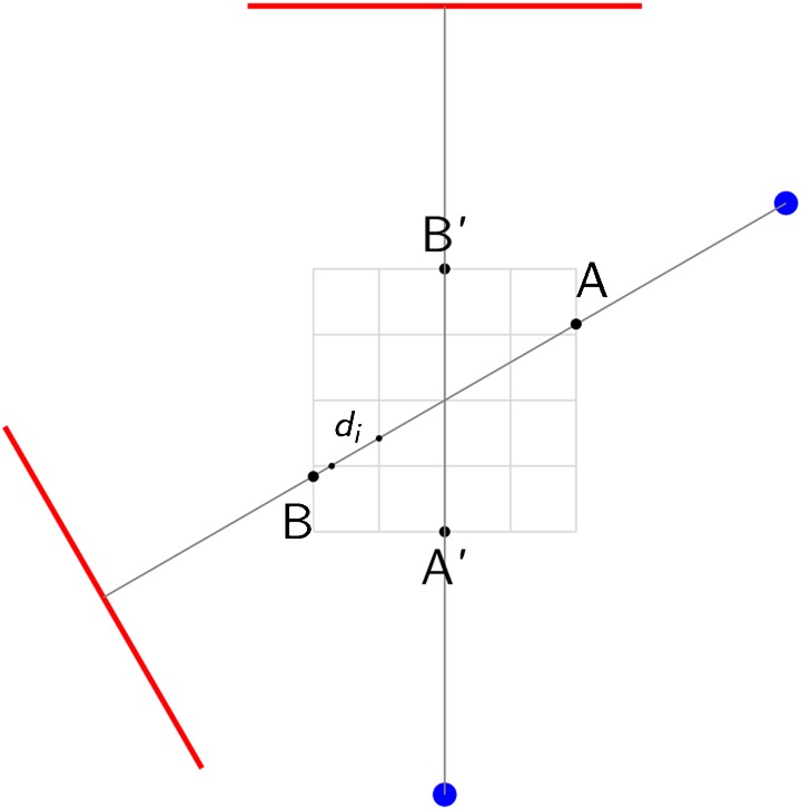
For two arbitrary positions (primed and unprimed) of the unit consisting of a point source (spots) and a detector (line) rotating around a centre of rotation, one exemplary measured “ray” is displayed. It enters the volume to be reconstructed at entry point A (or A′) and exits it in point B (or B′). The distance  the ray traverses through a particular voxel
  provides a simple measurement to compute the contribution of the “ray” to the grey value in voxel
Here  denotes the absorption of the object in a locus at position
  along the projection line containing
  absorbing loci along the measured “ray”. Hence,
  is commonly termed “raysum”. For the reconstruction, the task is to fill the object's image cells (or voxels) with grey values, each of which represents the local X-ray absorption of the object at that locus. Now recall that we know precisely the projection geometry for each projection from the construction of the imaging machine. In other words, one can precisely construct all lines connecting the detector cells with the source spot for each projection. We now assume that we reconstruct the entire object that has been traversed by the measured “rays”, i.e. that we do not have a “local tomography problem” here. In this case, the attenuation value
  recorded in detector cell
  is now backprojected along its projection line towards the source position for that projection. For this purpose, the intensity
  is smeared backwards through all pixels (or voxels) traversed through the object from point
  to
to  (Figure 1). Mathematically, the simplest way to do this would be to divide the value
  by the number of voxels
  traversed and assign each of the voxels the fraction
  . Obviously, this would be a rather crude way to backproject the intensity, since the distances
  the “ray” travels through each of the voxels traversed vary considerably (Figure 1). Hence, an improvement would be to calculate the distance
  for every voxel or, even better, to compute the volume the pyramidal “ray” shares with the considered voxel. It is well known that the better the interpolation scheme, the fewer aliasing artefacts (line patterns) will appear in the volume.18,19 Of course, backprojecting the intensities from one single projection does not yield meaningful grey values in the volume. Since it is not possible to decide how each voxel along the “ray” has contributed to the raysum, it is also impossible to assign a correct density and a correct grey value. To obtain a sufficient estimation, a high number of projections are needed (commonly several hundreds up to 1000). Owing to its simplicity and easy implementation, the backprojection algorithm applied in current CBCT machines is predominantly the Feldkamp algorithm.5 It is important to note that this concept of backprojection holds for all reconstruction methods, regardless of the actual mathematical procedure used to solve the reconstruction problem.
In summary, the circular orbit, the discrete representation of the object, quantum noise of the detector itself, crude interpolation methods and many other influences yield errors in the volume data. If they are visible then we refer to them as artefacts. These will be discussed in detail in the following sections.
Artefacts in CBCT — an overview
An image artefact may be defined as a visualized structure in the reconstructed data that is not present in the object under investigation. Generally speaking, artefacts are induced by discrepancies between the actual physical conditions of the measuring set-up (i.e. the CBCT scanner's technical composition plus the composition, position and behaviour of the object under investigation) and the simplified mathematical assumptions used for 3D reconstruction.
In the scientific literature, the following relevant artefacts are reported:
extinction artefacts;
beam hardening artefacts;
partial volume effect and EEGE;
aliasing artefacts;
ring artefacts; and
motion artefacts (misalignment artefacts).
In addition, noise and scatter are well known to produce additional artefacts. In the following section, we will briefly summarise the information available in the literature for each of these artefact-causing factors. It is important to note that artefacts represent themselves very often by streaks, line structures and shadows orientated along the projection lines. Although in the following section we attempt to distinguish between the causes of streak-like artefacts, it should be emphasized that many of the artefact-causing factors reported here have a streak-like appearance.20
General artefact-causing effects
Some factors that cause general inconsistencies in the reconstructions, i.e. artefacts, may not be easily depicted as specific patterns but as a more general deviation of the reconstructed density (grey) values from the “true” ones. One such factor is apparent in small field of views (FOVs), where the FOV is just a small part of the entire object that is being traversed by the X-rays. This phenomenon is called local tomography: in local tomography the region of interest is surrounded by tissue that is not reconstructed.21 The raysum is measured over all objects traversed by the “ray”, i.e. in the case of local tomography, over structures that are outside the FOV that is later reconstructed. These structures are only in the beam over small angular ranges, yet the backprojection process does not account for that. There is no easy way to overcome this problem which again causes inconsistencies (errors) in the reconstructed volume.
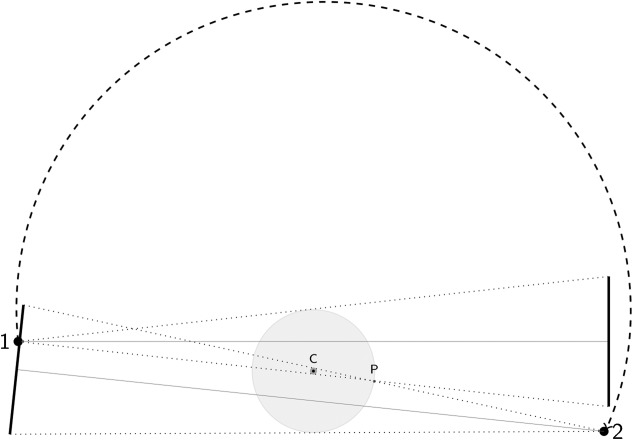
Another error is linked to a hardware limitation and the costs of large flat-panel detectors necessary to acquire large volumes. Such detectors are very costly and thus the manufacturers came up with a technical solution which is now frequently used in commercial CBCT machines: they use a smaller size flat-panel with the source-detector axis positioned offset to the centre of rotation (Figure 2). The consequence is that the central (cylindrical) part of the reconstructed volume is scanned over a complete 360° rotation, while locations at the periphery are only scanned over a 180° half-rotation (plus cone angle at maximum, depending on their distance from the centre of rotation and the imaging geometry). The abrupt transition between the two regions may result in a ring artefact in this area in the axial planes.
Figure 2.
Geometric setting when a smaller detector is applied and the center of rotation (C) is offset relative to the source-detector axis which is aligned with the central X-ray. Note, that only the darker grey-shaded inner circular portion of a circular field of view (FOV) remains in the beam over the entire circle (360°). The light grey-shaded portions of the FOV outside that area are only in the beam over a maximum angular range of 180° plus cone angle (depending on the imaging geometry and their distance from the point of rotation). For a point P located on the outer border of the object, this angle is defined by the two source positions (1,2) displayed here
Predominant artefacts in detail
Noise
Although noise is commonly not dealt with as an artefact, it is an image deteriorating factor.20 Two sorts of noise have to be considered in the reconstructed images:22 additive noise stemming from round-off errors or electrical noise, and photon-count noise (quantum noise) that should be expected to follow a Poisson distribution.23 Other authors also include detector blurring in the term “noise”.24 CBCT machines for dose reduction reasons are operated at milliamperes that are approximately one order of magnitude below those of medical CT machines. Thus, the signal-to-noise ratio is much lower than in CT. In other words, a high noise level is to be expected in CBCT images. Noise represents itself in inconsistent attenuation (grey) values in the projection images, i.e. large standard deviations in areas where a constant attenuation should be present. When backprojecting these incorrect values, the computed attenuation coefficient  in the volume will also be erroneous.
Scatter
Scatter seems to also be a very important artefact-causing factor in CBCT.25 The basic concept behind the radiographic imaging process as described in Equation 1 is that only photons travelling directly (i.e. in a line-path) from the source to the detector are measured. Scatter, on the other hand, is caused by those photons that are diffracted from their original path after interaction with matter. This additional share of scattered X-rays results in increased measured intensities, since the scattered intensities simply add to the primary intensity ( ).
).
It is easy to see that backprojection of overestimated intensities yields overestimated intensities in every voxel along the path; this corresponds to an underestimation of absorption, i.e.
 . This effect has long been known for classical CT.26 The reconstructed error is dependent on the object and is proportional to the amount of scatter present.27
Considering the geometry of (large) area detectors, it seems quite obvious that the larger the detector, the higher the probability that scattered photons incite it. Thus, the image-degrading effect of scattered radiation will affect CBCT machines more than classical highly-collimated fan-beam CTs.7,8 Scatter causes streak artefacts in the reconstruction that are very similar to those caused by beam hardening.20 Scatter is well-known to further reduce soft-tissue contrast27 and it will also affect the density values of all other tissues.
Extinction artefacts
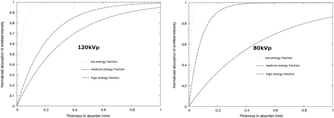
These are often termed “missing value artefacts”. If the object under study contains highly absorbing material, e.g. prosthetic gold restorations, then the signal  recorded in the detector pixels behind that material may be close to zero or actually zero. To illustrate this effect, one has to note that for a typical aluminium filtration of 2 mm to 3 mm, the average energy contained in the polychromatic spectrum is roughly half of the peak energy.28,29 Also, owing to the distribution of the wavelengths, the majority of wavelengths will be centred around that average value.28 A typical gold crown may be estimated to have at least 2 mm to 3 mm of thickness (when considering that the X-rays have to pass through both sides of it). This results in an absorption of the mean energy of 90% to 97% (Figure 3; for the mass absorption coefficients see http://physics.nist.gov/PhysRefData/XrayMassCoef/ElemTab/z79.html). Clearly, two gold restorations or even one with thicker walls will result in zero incident intensity on the detector. Consequently, no absorption can be computed and severe artefacts are induced as these zero entries are backprojected into the volume.30
Figure 3.
Assuming a simplified polychromatic model with three energetic subfractions for two maximum beam energy settings (120 kVp, left plot, and 80 kVp, right plot), the resulting absorption within gold is plotted vs the absorber thickness for each energy subfraction. Clearly, the lower energetic fractions which contain the maximum of wavelengths in a typical spectrum are massively absorbed by a gold restoration in the beam
Beam hardening artefacts
Beam hardening is one of the most prominent sources of artefacts.20,31 The lower energetic (lower wavelength) rays of the polychromatic spectrum emitted by the X-ray source may suffer substantial absorption when passing through the object under study. The more dense the latter and the higher the atomic number it is composed of, the larger the share of absorbed wavelengths. Highly absorbing material such as metal functions as a filter positioned within the object. At the same time, Equation 1 assumes monochromatic X-rays simply because the energy, and consequently the intensity, is inversely proportional to the wavelength. If the emitted spectrum contains more relatively lower energetic rays than that recorded on the detector (i.e. the beam is hardened), a non-linear error (relatively too much energy recorded in the beam path behind highly absorbing materials) is induced in the recorded data. In the 3D reconstruction, the error is backprojected into the volume, resulting in darks streaks.20 It has been shown that even light metal such as titanium causes massive beam hardening for the typical kilovoltages applied in CBCT machines.17
Exponential edge gradient effect
This effect appears at sharp edges with high contrast to neighbouring structures (Figure 4). It is caused by averaging the measured intensity over a finite beam width (and finite focal spot width), while the mathematics used for the reconstruction assume zero width. In other words, the inversion formulas such as the Feldkamp algorithm assume true lines in a mathematical sense over which the attenuation is integrated, whereas in reality the “lines” measured the average absorption over a finite “line” width. The width is determined by the focal spot and detector pixel size in combination with the imaging geometry of the machine. The EEGE error induced in the projection values has been proven to always be negative,32 i.e. it will always reduce the computed density value. The EEGE is known to cause streaks tangent to long straight edges in the projection direction20 (Figure 4). As sharp edges of high contrast may commonly occur in the oral cavity, e.g. at metallic crown borders, this artefact also has to be considered in dental CBCT. When extending the logical clues introduced by Joseph and Spital in their in-depth analytical investigation of the EEGE32 for conventional fan-beam CT, it seems obvious that the EEGE for CBCT geometries is equivalent to another effect described for common fan-beam CT in the axial (z-) direction: the partial volume effect. The latter had been introduced by the truncation of the data in z-direction owing to the slice-wise acquisition concept.
Figure 4.
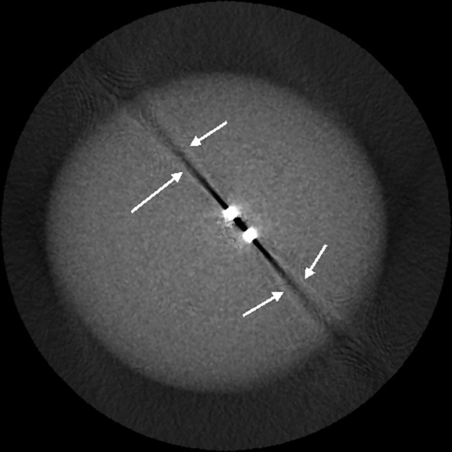
Exponential edge-gradient effect (EEGE) with typical thin lines tangent to sharp edges (arrows) in the direction of the beam20
Aliasing artefacts
Aliasing is caused when the fundamental Nyquist sampling theorem is violated. It requires that, in order to completely reconstruct a continuous signal, the sampling frequency must be higher than twice the highest frequency contained in the signal. In imaging, the sampling frequency is represented by the numbers of pixels per area, i.e. the pixel size of the detector. The size of the detector elements causes aliasing artefacts owing to under-sampling.18 Another typical factor causing aliasing in CBCT lies in the divergence of the cone beam.2 As demonstrated in Figure 5, in each projection the voxels close to the source will be traversed by more recorded “rays” than those close to the detector. This causes aliasing which represents itself as line patterns (moire patterns), commonly diverging towards the periphery of the reconstructed volume (Figure 6).
Figure 5.
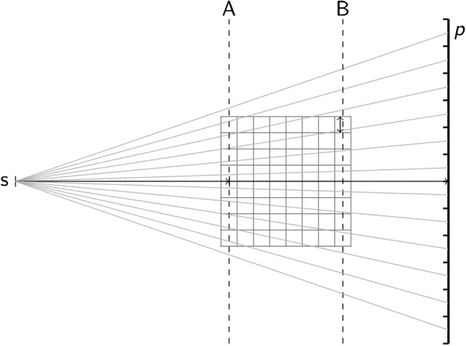
One source of undersampling resulting in aliasing errors in cone beam CT (CBCT) is the cone divergence itself. Obviously, the slice A of the volume nearest to the source s collects many more “rays” per voxel (as measured on the detector pixels, p) than slice B, which is closest to the detector. The number of rays per voxel linearly decreases with the distance of the slice from the source s
Figure 6.
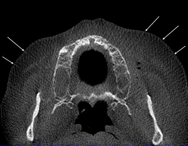
Typical aliasing patterns (Moire patterns) in cone beam CT (CBCT) data sets. The lines (arrows) diverge from the centre towards the periphery and are most probably caused by the undersampling owing to the cone beam geometry illustrated in Figure 5
Aliasing may also be introduced by a crude interpolation between the backprojection “lines” and the voxel they traverse. Ideally, the exact volume a voxel shares with the “line-fragment” ( ) (Figure 1) crossing through it should be used to compute the intensity of the voxel. Owing to computational limitations, however, often only crude but fast approximations (i.e. the length of the fragment33) enter the computation. This causes aliasing artefacts which can be avoided by a better interpolation scheme that is more closely conforming with the actual physical measurement conditions.18,19
Ring artefacts
Ring artefacts (Figure 7) are visible as concentric rings centred around the location of the axis of rotation. They are most prominent when homogeneous media are imaged. Apparently they are caused by defect or uncalibrated detector elements.3,8 Owing to the circular trajectory and the discrete sampling process, these inconsistencies appear as rings in the planes coplanar with the movement plane of the source (axial planes in CBCT). We have not observed ring artefacts in our iterative technique based on the algebraic reconstruction concept,19 which is owing to the fact that algebraic algorithms deal better with these “noise-like” inconsistencies than filtered backprojection types of algorithms. In a broader sense, ring artefacts could also be allocated to the group of aliasing artefacts.
Figure 7.
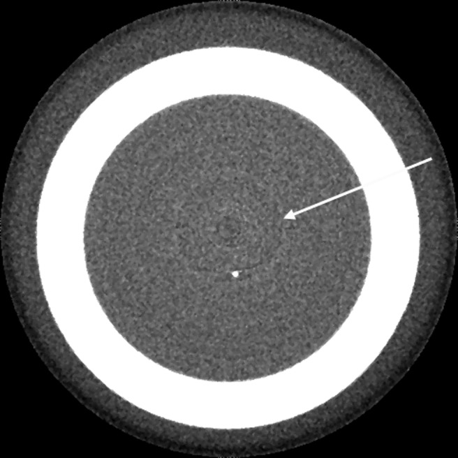
Ring artefacts (arrow) centred around the location of the axis of rotation in the image. As with many other artefacts, they are most clearly visible in axial slices, i.e. in beam direction
Motion artefacts—misalignment artefacts
These two sources of error are closely related in that a misalignment of any of the three components (source, object and detector) causes inconsistencies in the backprojection process. The general problem is quite easy to explain for patient motion artefacts. If an object moves during the scanning process, the reconstruction does not account for that move since no information on the movement is integrated in the reconstruction process. Hence, the lines along which the backprojection takes place do not correspond to the lines along which the attenuation had been recorded, simply because the object has moved during the acquisition. The backprojection assumes a completely stationary geometry. Consequently, the intensities contained in the projections are backprojected under the static assumption, whereas de facto a correction exactly compensating the actual movement effective in each of the projections would be required. The acquisition time of state-of-the-art CBCT machines roughly ranges between 6 s and 20 s, hence there is enough time for a human head to perform some minor movement. Obviously, the smaller the voxel size (i.e. the higher the spatial resolution), the smaller the movement necessary to move the patient structures out of the “correct” voxels. In other words, the higher the nominal resolution, the more likely motion artefacts are to appear. Typically, movement artefacts present as double contours (Figure 8). A sufficient fixation of the patient's head during the scan process should help to limit the movement options for the patient. Also, it is reasonable to assume that future detector hardware will enable faster detector read-out, thereby reducing scanning times and thus chances for patient movement.
Figure 8.
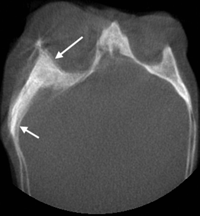
Typical double contours (arrows) induced by patient movement during the acquisition process of the projection images
Misalignment of the source relative to the detector or the unit of the two of them relative to the stationary patient causes the same sort of inconsistencies as described above. This applies also for minute deviations,7 e.g. deviations from a truly planar circular source and detector trajectory. To prevent these sorts of errors poses great challenges on the mechanical stability of the systems.34
Summary and conclusions
As stated by the famous developer of spiral CT, Willy Kalender, flat-detector CBCT scanners suffer from problems such as beam hardening, defect detector elements or metal artefacts like any other X-ray CT imaging system.7 Since the fundamental measurement process and that used for reconstruction are identical, from a technical point of view, this statement is almost self-evident. The common misconception among some users of CBCT machines that CBCT data sets contain fewer artefacts than their CT counterparts9,10 may be explained by different windowing and levelling conditions or different post-processing algorithms. De facto CBCT involves additional artefacts, such as aliasing artefacts caused by the cone beam divergence, scatter and a generally higher noise level. The Feldkamp algorithm,5 which is the most widely used at the time this review was written, will only guarantee a high image quality in the central plane, where, from a mathematical point of view, it is identical to the filtered backprojection used in CT machines.5 Image quality, however, will degrade as a function of distance from that plane.7 This additional aspect should be born in mind, particularly when evaluating large FOV volumes. Actual state-of-the-art algorithms such as the theoretically exact algorithm introduced by Katsevich35 are not yet implemented since this is much more complicated to achieve because it would imply a helix-source trajectory.
It is no surprise that the technical community puts considerable efforts into developing techniques for artefact reduction. Many of them are post-processing algorithms operating on the 3D volume data.25,36-38 Although this may result in considerable reduction of some apparent artefact structures, from a physical point of view post-processing is like putting the cart before the horse since the error has been integrated into the volume already. Consequently, more modern approaches attempt to avoid reconstruction errors either by supplementing missing or incorrect information in the projection images8,39,40 or by integrating some sort of meta-information into an iterative reconstruction process.41-43 Aliasing artefacts have been successfully suppressed already by using more sophisticated projection and backprojection techniques.2,13,18,19 All these methods, however, require massive computational power, so far preventing them from being used in commercial scanners in daily routine work. The ever-increasing computational speed, however, and particularly the advancement in graphics processing units, has already drastically reduced the computational time required.44 As this process will continue, it is very likely that enhanced reconstruction methods will be much more common in the near future. They will help to reduce various sorts of artefacts.
References
- 1.Radon J. Über die Bestimmung von Funktionen durch ihre Integralwerte längs gewisser Mannigfaltigkeiten. Ber Verh Sächs Akad Wiss Leipzig, Math Phys Kl 1971;69:262–277 [Google Scholar]
- 2.Mueller K. Fast and accurate three-dimensional reconstruction from cone-beam projection data using algebraic methods.1998Ohio, USA: Dissertation at the Ohio State University [Google Scholar]
- 3.Yu L, Pan X, Peliizari CA. Image reconstruction with a shift-variant filtration in circular cone-beam CT. Int J Imaging Syst Technol 2005;14:213–221 [Google Scholar]
- 4.Tuy HK. An inversion formula for cone-beam reconstruction. SIAM J Appl Math 1983;43:546–552 [Google Scholar]
- 5.Feldkamp LA, Davis LC, Kress JW. Practical cone-beam algorithm. J Opt Soc Am A 1984;1:612–619 [Google Scholar]
- 6.Sharp GC, Kandasamy N, Singh H, Folkert M. GPU-based streaming architectures for fast cone-beam CT image reconstruction and demons deformable registration. Phys Med Biol 2007;52:5771–5783 [DOI] [PubMed] [Google Scholar]
- 7.Kalender WA, Kyriakou Y. Flat-detector computed tomography (FD-CT). Eur Radiol 2007;17:2767–2779 [DOI] [PMC free article] [PubMed] [Google Scholar]
- 8.Zhang Y, Zhang L, Zhu XR, Lee AK, Chambers M, Dong L. Reducing metal artefacts in cone-beam CT images by preprocessing projection data. Int J Radiat Oncol Biol Phys 2007;67:924–932 [DOI] [PubMed] [Google Scholar]
- 9.Stuehmer C, Essig H, Bormann K-H, Majdani O, Gellrich N-C, Rücker M. Cone beam CT imaging of airgun injuries to the craniomaxillofacial region. Int J Oral Maxillofac Surg 2008;37:903–906 [DOI] [PubMed] [Google Scholar]
- 10.Hsieh J, Molthen RC, Dawson CA, Johnson RH. An iterative approach to the beam hardening correction in cone beam CT. Med Phys 2007;27:23–29 [DOI] [PubMed] [Google Scholar]
- 11.Holberg C, Steinhäuser S, Geis P, Rudzki-Janson I. Cone-beam computed tomography in orthodontics: benefits and limitations. J Orofac Orthop 2005;66:434–444 [DOI] [PubMed] [Google Scholar]
- 12.Katsumata A, Hirukawa A, Noujeim M, Okumura S, Naitoh M, Fujishita M, et al. Image artifact in dental cone-beam CT. Oral Surg Oral Med Oral Pathol Oral Radiol Endod 2006;101:652–657 [DOI] [PubMed] [Google Scholar]
- 13.Mueller K, Yagel R, Wheller JW. Anti-aliased three-dimensional cone-beam reconstruction of low-contrast objects with algebraic methods. IEEE Trans Med Imaging 1999;18:519–537 [DOI] [PubMed] [Google Scholar]
- 14.Valton S, Peyrin F, Sappey-Marinier D. Analysis of cone-beam artefacts in off-centered circular CT for four reconstruction methods. Int J Biomed Imaging 2006: 1–8 [DOI] [PMC free article] [PubMed] [Google Scholar]
- 15.Zou Y, Sidky EY, Pan X. Partial volume and aliasing artefacts in helical cone-beam CT. Phys Med Biol 2004;49:2365–2375 [DOI] [PubMed] [Google Scholar]
- 16.Draenert FG, Coppenrath E, Herzog P, Müller S, Mueller-Lisse UG. Beam hardening artefacts occur in dental implant scans with the NewTom cone beam CT but not with the dental 4-row multidetector CT. Dentomaxillofac Radiol 2007;36:198–203 [DOI] [PubMed] [Google Scholar]
- 17.Schulze RKW, Berndt D, d'Hoedt B. On cone-beam computed tomography artefacts induced by titanium implants. Clin Oral Impl Res 2010;21:100–107 [DOI] [PubMed] [Google Scholar]
- 18.de Man B, Basu S. Distance-driven projection and backprojection in three dimensions. Phys Med Biol 2004;49:2463–2475 [DOI] [PubMed] [Google Scholar]
- 19.Groβ D, Heil U, Schulze R, Schoemer E, Schwanecke U. GPU-based volume-reconstruction from very few arbitrarily aligned X-ray images. SIAM J Sci Comp 2009;31:4204–4221 [Google Scholar]
- 20.de Man B. Metal streak artefacts in X-ray computed tomography: a simulation study. IEEE Trans Nuc Sci 1999;46:691–696 [Google Scholar]
- 21.Siltanen S, Kolehmainen V, Jarvenpaa S, Kaipio JP, Koistinen P, Lassas M, Pirttil J, Somersalo E. Statistical inversion for medical X-ray tomography with few radiographs: I. General theory. Phys Med Biol 2003;48:1437–1463 [DOI] [PubMed] [Google Scholar]
- 22.Kak AC, Slaney M. Principles of computerized tomographic imaging. New York, USA: IEEE Engineering in Medicine and Biology Society, 1988 [Google Scholar]
- 23.Strid KG. Significance of quantum fluctuations in roentgen imaging. Acta Radiol Oncol 1980;19:129–138 [DOI] [PubMed] [Google Scholar]
- 24.Tu S-J, Shaw CC, Chen L. Noise simulation in cone beam CT imaging with parallel computing. Phys Med Biol 2006;51:1283–1297 [DOI] [PMC free article] [PubMed] [Google Scholar]
- 25.Altunbas MC, Shaw CC, Chen L, Lai C, Liu X, Han T, et al. A post-reconstruction method to correct cupping artefacts in cone beam breast computed tomography. Med Phys 2007;34:3109–3118 [DOI] [PMC free article] [PubMed] [Google Scholar]
- 26.Kanamori H, Nakamori N, Inoue K, Takenaka E. Effects of scattered X-rays on CT images. Phys Med Biol 1985;30:239–249 [DOI] [PubMed] [Google Scholar]
- 27.Tofts PS, Gore JC. Some sources of artefact in computed tomography. Phys Med Biol 1980;25:117–127 [DOI] [PubMed] [Google Scholar]
- 28.Epp ER, Weiss H. Experimental study of the photon energy spectrum of primary diagnostic X-rays. Phys Med Biol 1967;11:225–238 [DOI] [PubMed] [Google Scholar]
- 29.Waggener RG, Levy LB, Rogers LF, Zanca P. Measured X-ray spectra from 25 to 110 kVp for a typical diagnostic unit. Radiol 1972;105:169–175 [DOI] [PubMed] [Google Scholar]
- 30.Prell D, Kyriakou Y, Beister M, Kalender WA. A novel forward projection-based metal artifact reduction method for flat-detector computed tomography. Phys Med Biol 2009;54:6575–6591 [DOI] [PubMed] [Google Scholar]
- 31.de Man B. Reduction of metal streak artefacts in X-ray computed tomography using a transmission maximum a posteriori algorithm. IEEE Trans Nuclear Sci 2000;47:977–981 [Google Scholar]
- 32.Joseph PM, Spital RD. The exponential edge-gradient effect in x-ray computed tomography. Phys Med Biol 1981;26:473–487 [DOI] [PubMed] [Google Scholar]
- 33.Siddon RL. Fast calculation of the exact radiological path for a three-dimensional CT array. Med Phys;12:252–255 [DOI] [PubMed] [Google Scholar]
- 34.Kyriakou Y, Prell D, Kalender WA. Ring artifact correction for high-resolution micro CT. Phys Med Biol 2009;54:N385–91 [DOI] [PubMed] [Google Scholar]
- 35.Katsevich AI. Theoretically exact FBP-type inversion algorithm for spiral CT. SIAM J Appl Math 2002;62:2012–2026 [Google Scholar]
- 36.Barrett JF, Keat N. Artefacts in CT: recognition and avoidance. Radiographics;24:1679–1691 [DOI] [PubMed] [Google Scholar]
- 37.Prell D, Kyriakou Y, Kalender WA. Comparison of ring artifact correction methods for flat-detector CT. Phys Med Biol 2009;54:3881–3895 [DOI] [PubMed] [Google Scholar]
- 38.Tuy HK. A post-processing algorithm to reduce metallic clip artefacts in CT images. Eur Radiol 1993;3:129–134 [Google Scholar]
- 39.Rinkel J, Dillon WP, Funk T, Gould R, Prevrhal S. Computed tomographic metal artifact reduction for the detection and quantitation of small features near large metallic implants: a comparison of published methods. J Comput Assist Tomogr 2008;32:621–629 [DOI] [PubMed] [Google Scholar]
- 40.Kalender WA, Hebel R, Ebersberger J. Reduction of CT artefacts caused by metallic implants. Radiol 1987;164:576–577 [DOI] [PubMed] [Google Scholar]
- 41.Wang G, Vannier MW, Cheng PC. Iterative X-ray cone-beam tomography for metal artifact reduction and local region reconstruction. Microsc Microanal 1999;5:58–65 [DOI] [PubMed] [Google Scholar]
- 42.de Man B, Nuyts J, Dupont P, Marchal G, Suetens P. An iterative maximum-likelihood polychromatic algorithm for CT. IEEE Trans Med Imaging 2001;20:999–1008 [DOI] [PubMed] [Google Scholar]
- 43.Wang G, Snyder DL, Sullivan JA, Vannier MW. Iterative deblurring for CT metal artifact reduction. IEEE Trans Med Imaging 1996;15:657–664 [DOI] [PubMed] [Google Scholar]
- 44.Xu W, Mueller K. Accelerating popular tomographic reconstruction algorithms on commodity PC graphics hardware. IEEE Trans Nucl Sci 2005;52:654–663 [Google Scholar]


