Abstract
Objective
The aim of this study was to assess the characteristics of an optically stimulated luminescence dosemeter (OSLD) for use in diagnostic radiology and to apply the OSLD in measuring the organ doses by panoramic radiography.
Methods
The dose linearity, energy dependency and angular dependency of aluminium oxide-based OSLDs were examined using an X-ray generator to simulate various exposure settings in diagnostic radiology. The organ doses were then measured by inserting the dosemeters into an anthropomorphic phantom while using three panoramic machines.
Results
The dosemeters demonstrated consistent dose linearity (coefficient of variation<1.5%) and no significant energy dependency (coefficient of variation<1.5%) under the applied exposure conditions. They also exhibited negligible angular dependency (≤10%). The organ doses of the X-ray as a result of panoramic imaging by three machines were calculated using the dosemeters.
Conclusion
OSLDs can be utilized to measure the organ doses in diagnostic radiology. The availability of these dosemeters in strip form proves to be reliably advantageous.
Keywords: optically stimulated luminescence dosemeter, dosimetry, organ dose, diagnostic radiology
Introduction
The application of radiology in the dental and maxillofacial regions has increased considerably over the last few decades. The advent of new technological applications has increased the need for assessing the risk-to-benefit relationship associated with the use of these modalities in diagnostic radiology. The measurement of organ dose is essential in the estimation of the relative risk of cancer induction associated with diagnostic radiation. One of the methods employed to estimate organ doses involves embedding dosemeters in a tissue-equivalent anthropomorphic phantom. Thermoluminescence dosemeters (TLDs) have been commonly utilized in such measurements. Optically stimulated luminescence (OSL) dosimetry is another technique that is employed in many areas of radiation dosimetry, including personal monitoring, in vivo dosimetry and for generating dose profiles in the estimation of CT dose index (CTDI).1-3 TLDs require complicated handling to read the device under fully controlled temperature changes and they employ sophisticated methods to thermally anneal the TLDs for reuse.4 OSL dosemeters (OSLDs) have now been used for monitoring occupational radiation doses for more than a decade.5 The OSL phenomenon can be explained within the same framework used to explain the thermoluminescence process, but with additional optical transitions that can occur when the material is exposed to light. The basic principle of the OSLD can be explained in a simplified way. The crystalline structure of the dosemeter ingredient has three bands of energy levels: the valence band, the conduction band and the forbidden band, which separates the first two bands. The trapping of electrons from the valence or conduction bands occurs in the forbidden bands on exposure to an ionizing radiation. When exposing crystal to visible light, the stored energy is emitted proportionately in the form of light because of the optical transition of electrons occurring among the bands.6
Because OSLDs are available as sheets, they can be easily fabricated into strips and inserted into phantom slots of various sizes and shapes. The strip-like form of OSLDs, however, may make them susceptible to sensitivity loss depending on the incident direction of radiation when assessing the specific absorbed dose distribution. There is also a need to characterize the OSLD for the energy levels used in dental maxillofacial imaging modalities, which are typically lower than those found in other applications.
We conducted a thorough assessment of the performance of OSLDs by testing their dose linearity, energy dependency and angular dependency under all diagnostic radiological exposure settings. The organ doses were then measured during the use of three conventional panoramic machines using the OSLD.
Materials and methods
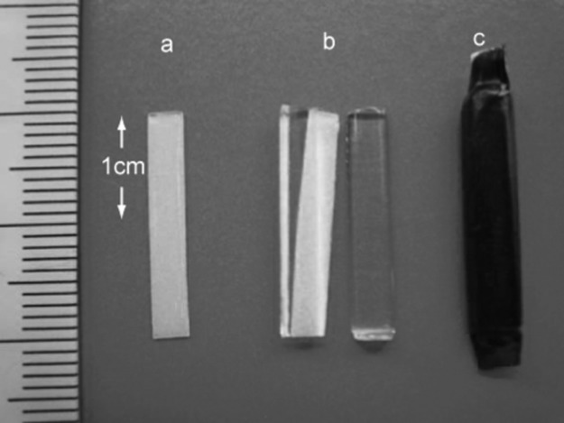
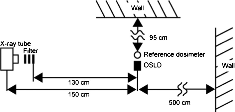
The OSLD elements utilized were aluminium oxide doped with carbon activator Al2O3:C (ALOC)-based OSLD sheets manufactured by Landauer Ltd (Glenwood, IL ), which were cut into strips measuring 20 mm in length and 3 mm in width by Nagase Landauer Ltd. (Ibaraki, USA), as depicted in Figure 1. The inhomogeneity in the sensitivity of these elements is reported to be less than 5% by 1 mGy irradiation of 137Cs gamma rays (663 keV).1 Each strip was sandwiched by two half-cut polymethyl methacrylate (PMMA) cylinders on both sides to stabilize it in the phantom. Each strip was covered with a visible light protective sheet, as depicted in Figure 2. The dosemeters were also assessed without the PMMA cover to estimate the effect of acrylic, if any, on their dosimetric properties. The OSLD readings were measured using a manual luxel reader (Landauer Ltd.). This apparatus displays the apparent dose in Sv. Dosimetric estimates were made by averaging the responses at three areas on each strip, as illustrated in Figure 1. The experimental set-up for characterization of the OSLD is depicted in Figure 3. The X-ray generator used in the study was MG165 (Philips, Hamburg, Germany). The machine has an inherent filtration of 1.0 mm of beryllium and a filter of 3.7 mm-thick aluminium was added. The focus–detector distance was 150 cm. The irradiated field was circular and its diameter was 15 cm at the position of the detector.
Figure 1.
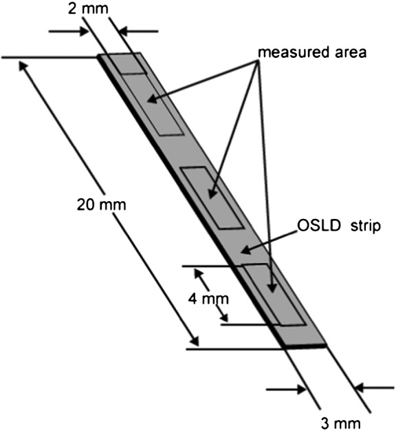
Diagrammatic representation of an optically stimulated luminescence dosemeter (OSLD) strip showing dimensions and measurement areas
Figure 2.
Photograph of an optically stimulated luminescence dosemeter (OSLD) strip (a), strip with half-cut polymethyl methacrylate cylinders (b), and OSLD covered in a visible light protective sheet (c)
Figure 3.
Schematic representation of the experimental set-up. OSLD, optically stimulated luminescence dosemeter
Calibration of OSLD
The absorbed dose in the cavity is proportional to the mass energy absorption coefficient of the cavity.7 When we consider an organ dose, we assume that the cavity is filled with the organ. When the radiation dose in the phantom is measured, the cavity is filled with the detector material. If the detector is an ideal ionization chamber, the cavity is thought to be filled with air and the dose is called the “air dose”. When the detector is not air, the dosemeter should be calibrated to the air dose. The calibration coefficient includes the ratio of the mass energy coefficients of the detector material to air and the overall system gain of the dosemeter. The calculated value, as the product of the reading of the OSLD and the calibration coefficient, is therefore the air dose. Dosemeters covered by PMMA were calibrated using RAMTEC 1000D (Toyo Medic Co., Ltd., Tokyo, Japan) with a Model A4 Exradin (30 cm3 in volume) ionizing chamber as a reference dosemeter. The reference dosemeter was approved and calibrated according to the reference dosemeter of the Japan Quality Assurance Association, which was calibrated by the national standard of Japan. The air dose was first measured using the reference dosemeter. The OSLD, placed at the same location as the reference dosemeter, was then exposed. The reference dosemeter was again used to measure doses at the same location. The air dose at the detector point was determined as the average of the two measurements by the reference dosemeter. The response of the OSLD [R (Sv/Gy)], which is defined as the reciprocal of the calibration coefficient [N (Gy/Sv)], was determined by the quotient of the reading [r (Sv)] from the OSLD by the air dose [D (Gy)] measured from the reference dosemeter:
| (1) |
Dose linearity
The OSLD elements were perpendicularly exposed to the X-ray using a tube voltage of 70 kV. As a reference, tube current and exposure time were adjusted to obtain a certain dosage in the air with the following combinations: 1.1 mA and 5 s for 0.1 mGy; 5.5 mA and 5 s for 0.5 mGy; 11 mA and 10 s for 2 mGy; 22 mA and 25 s for 10 mGy; 22 mA and 125 s for 50 mGy; or 22 mA and 250 s for 100 mGy. The response R for each dose was calculated as the average response from all five elements using Equation (1). The responses thus derived were then divided by the average doses used in exposing the dosemeters to obtain a relative response normalized to the average response over six dose points. These values were then used to plot a graph for dose linearity with relative response and exposure doses on the opposing axes.
Energy dependency
Out of a total of 90 elements, 5 elements each were irradiated with approximately 2.15 mGy using 9 different tube voltages of 40 kV, 50 kV, 60 kV, 70 kV, 80 kV, 90 kV, 100 kV, 120 kV or 140 kV; the effective energies for each were 26.8 keV, 29.1 keV, 31.0 keV, 32.7 keV, 34.4 keV, 36.1 keV, 37.8 keV, 41.1 keV or 44.4 keV, respectively. The irradiating beam quality was standardized by use of additional filters so that at 70 kV the half-value layers (HVLs) was 3 mm aluminium. The HVLs were then measured for each tube voltage using the “HVL mode” of NERO® (Non-invasive Evaluator of Radiation Outputs®, mAx model 8000, Victoreen, Cleveland, OH). The measured HVLs were subsequently used to derive the effective energies from the National Institute of Standards and Technology (NIST) database.8 The average R of five elements for each energy level was used to plot the energy dependency graph. The experiment was performed with and without the PMMA covers separately.
Angular dependency
For the angular dependency tests, five elements each were exposed at tube voltages of 50 kV, 70 kV or 140 kV. The incident angles of the X-ray beam to the elements were 0°, 30°, 60° or 90° in both polar and azimuthal directions, as depicted in Figure 4. The elements were positioned at seven different angulations with or without PMMA, as a 0° polar and azimuthal angle refers to the same spatial locations. 210 OSLD elements were thus used. The average responses for each incident angle were then expressed in relation to the response for the 0° azimuthal and polar angles in the respective graphs.
Figure 4.
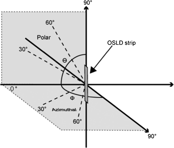
Definition of X-ray incident angles to the optically stimulated luminescence dosemeter strip. OSLD, optically stimulated luminescence dosemeter
Measurement of organ dose
Organ doses from three panoramic X-ray units were measured in this study. The machines employed the following operating parameters: Hyper-XF® (Asahi Roentgen, Kyoto, Japan), 78 kV, 10 mA, 12 s; PanoACT®-1000 (Axion Japan, Tokyo, Japan), 80 kV, 6 mA, 12 s; and OP 200D® (Instrumentarium, Finland), 66 kV, 10 mA, 17.6 s. The effective energy was estimated on the basis of the value of the HVL as described in the paragraph for energy dependency above. The HVL and the effective energies measured were as follows: Hyper-XF®, 2.87 mm aluminium, 33.8 keV; PanoACT®-1000, 2.75 mm aluminium, 33.2 keV; and OP 200D®, 2.80 mm aluminium, 33.5 keV, respectively. As the coefficient of variation of the responses (r) obtained from each machine was within 0.6%, an average effective energy of 33.5 keV was considered as a reference level in further calculations. The tissue-equivalent anthropomorphic phantom, RANDO® (The Phantom Laboratory, New York, NY), was transversely cut into 34 slices from the scalp to the head of the pelvis with a slice thickness of 25 mm. The brain, eye lens, parotid gland, submandibular gland, thyroid gland, bone marrow (in the body of the mandible) and breast were selected for the measurement of organ doses. 32 OSLDs in PMMA covers were inserted in such organs (Table 1). In order to obtain reliable readings with the dosemeters, the exposures were iterated 100 times for the PanoACT®-1000 and OP 200D® and 50 times for the Hyper-HF®. The number of iterations was decided on the basis of the operating parameters and dose estimates using ionization chambers. The cumulative dose after these iterations was then divided by respective number of iterations for each machine to obtain the dose for each exposure. The organ dose was determined by averaging the values for all dosemeters embedded in the organ per irradiation. The reading r obtained by the OSLD was then multiplied by the calibration factor, N33.5, obtained for the energy of 33.5 keV to calculate the air dose, Dair (Gy). The value was further multiplied by the respective dose conversion factors, Corgan, to derive the dose values Dorgan (Gy) for each organ:
| (2) |
Table 1. Organs selected and distribution of dosemeters in the phantom.
| Organ | Location | Number of OSL | Phantom level |
| Brain | Right/midline/left | 2/1/2 | 3,4,5 |
| Eyes | Right/left | 2/2 | 4 |
| Parotid gland | Right/left | 3/3 | 6 |
| Submandibular gland | Right/left | 2/2 | 7 |
| Sublingual gland | Right/left | 1/1 | 7 |
| Bone marrow (mandible) | Right/midline/left | 1/1/1 | 7 |
| Thyroid | Right/left | 2/2 | 10 |
| Breast | Right/left | 2/2 | – |
OSL, optically stimulated luminescence.
| (3) |
The dose conversion factor used for soft tissue (excluding red bone marrow) was 1.06,9 red bone marrow was 1.0910 and bone surface was 5.08.9
Results
The obtained results were as follows:
Dose linearity
The relative response of the values from 0.1 mGy to 100 mGy is depicted in Figure 5. The relative response value for the entire dose range was between 0.984 and 1.02. The coefficient of variation was less than 1.5% for all measured points.
Figure 5.
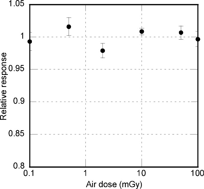
Relative responses of the dosemeters to exposure doses, showing the dose linearity of optically stimulated luminescence dosemeters
Energy dependency
The response of the OSLD varied from approximately 4 Sv/Gy at 25 keV to 3 Sv/Gy at 45 keV, which is the usual range of energy used in diagnostic radiography, as illustrated in Figure 6. There was no significant difference between the OSLD with and without a PMMA cylinder. The coefficient of variation was less than 1.5% for all measured points.
Figure 6.
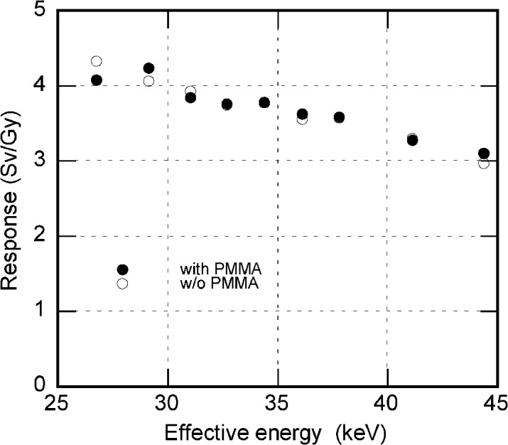
Relative responses of the dosemeters charted against effective energy, showing the energy dependence of optically stimulated luminescence dosemeters
Angular dependency
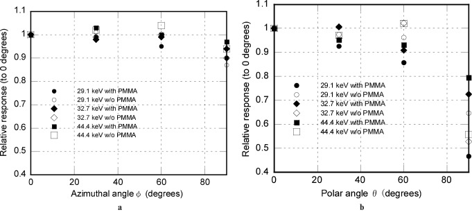
This was expressed as a relative response to each angle in relation to that at 0°; the results are shown in Figure 7a,b. At the azimuthal angle of 60°, the relative response was 0.984; it reduced to 0.903 at 90°. At the polar angle of 60°, the response was 0.857; it reduced to 0.467 at 90°.
Figure 7.
Relative responses of the dosemeters as a function of variation in azimuthal angle (a) and polar angle (b). PMMA, polymethyl methacrylate
Organ dose
The calibration coefficient, N33.5, obtained for the energy level of 33.5 keV was 0.26 Gy/Sv. Considering this factor and the dose correction factors, final organ doses were calculated and are presented in Table 2. The table also contains values of organ doses as calculated by Ludlow11 and Gavala12 using TLDs. Parotid glands received the highest exposure in all three machines. The machines exhibited a wide range of variations in the organ doses, with PanoACT®-1000 causing the least amount of exposure.
Table 2. Organ doses, in mGy, during panoramic imaging obtained by using optically stimulated luminescence dosemeters and those obtained by Ludlow11 and Gavala12 using thermoluminescence dosemeters.
| Tissue | Asahi Hyper-X |
PanoACT-1000 |
OP200 |
Orthophos (Ludlow et al)11 |
Proline2000 (Gavala et al)12 |
| (78 kV/10 mA/12 s) | (80 kV/6 mA/12 s) | (66 kV/10 mA/17.6 s) | (66 kV/16 mA/14.1 s) | (66 kV/8 mA/18 s) | |
| Brain | 0.085 | 0.019 | 0.047 | 0.035 | 0.100 |
| Eye lens | 0.052 | 0.012 | 0.021 | 0.020 | 0.055 |
| Parotid gland | 0.792 | 0.728 | 0.866 | 0.740 | 0.510 |
| Submandibular gland | 0.739 | 0.177 | 0.311 | 0.625 | 0.675 |
| Sublingual gland | 0.190 | 0.060 | 0.108 | 0.540 | 0.023 |
| Thyroid | 0.437 | 0.298 | 0.329 | 0.050 | 0.088 |
| Bone marrow (mandible) | 0.205 | 0.069 | 0.110 | 0.578 | 0.155 |
| Breast | 0.003 | 0.001 | 0.001 | NA | NA |
Discussion
The field of archaeology was the first to use the phenomenon of OSL for dosimetry.13 The accidental finding of the OSL property of ALOC crystals, which was originally synthesized for thermoluminescence, brought about an expanded application range and an increase in OSLD sensitivity. OSLDs are reusable and can also be used as a permanent record of the absorbed dose as they can be read long after the irradiation. The readout process is simpler, faster and easier compared with that of TLDs.1
The OSLD assessed in our study exhibited no significant difference in responses with or without the PMMA cover. This finding suggests that the secondary electrons emerging from the PMMA cylinder scarcely affect the OSL emission and that cavity theory7 can therefore be applied in the OSL dosimetry of diagnostic X-rays. We can therefore conclude that they can be covered by PMMA in order to stabilize and protect them without affecting their dosimetric performance.
The dose linearity of OSLD can vary depending on the crystal growth, the exposure settings and the readout conditions. In our experimental set-up, we found linearity with a coefficient of variation of 1.5%, suggesting a broad linearity over the dose range of 0.1 mGy to 100 mGy. We made no dose linearity correction in the determination of organ dose, distributed in a wide dose range from the highest on the entrance surface to the lowest at the site far from the beam, as the OSLD exhibited linearity over a wide dose range.
The angular dependency, as measured within all the possible variations of polar and azimuthal angles, was within acceptable limits and was better than the reported TLD variations.14 The incident angles of photons by virtue of experimental set-up in our study were within 10°, and the relative responses of the OSLD placed at a 30° polar angle was 0.93, suggesting an underestimation of approximately 7%. At a 90° azimuthal angle, the relative response was 0.90, suggesting a 10% underestimation. In an isotropic irradiation field, the radiation is considered to be distributed equally throughout the horizontal plane. In this experiment, the radiation was measured at 4 different angles separated by 30° each. This implies that each dosemeter may receive only the part of the photons which lie in the zone between two measuring points. Although the field is not isotropic in this experiment, it may be assumed that only a maximum of one-third of the radiation can be received at a 90° azimuthal angle, even if it was an isotropic irradiation field. Therefore, the calculated underestimation of 10% for this angle actually means about 3% (one-third of 10%). Thus, the overall underestimation for both planes included would not be more than 10% when used in a phantom.
Organ doses caused by the three panoramic machines exhibited similar values. Among them, PanoACT®-1000 exhibited relatively lesser values. Several studies regarding the absorbed doses have been published.11,12,15-17 Within experimental limits, variations are bound to occur in the results of various studies because of the phantoms used, the variations in dosemeter placement in the phantom and also the type of radiation source. The experiments of Ludlow11 and Gavala12 using a TLD exhibit organ doses in the same range as that obtained in our study using an OSLD.
The fact that OSLDs are available in strip form makes them suitable for measuring organ doses in structures like the oral mucosa, airway etc., as they need to be calculated using the latest International Commission on Radiological Protection publication 103.18 They may also be used to evaluate the dose profiles of various cone beam CT machines as they are simpler than TLDs. OSLDs are consistent in terms of response at the energy levels employed in dental maxillofacial radiology and they have no significant angular dependencies. The results of our experiment indicate that OSLD performance is sensitive and reliable, paving the way for future endeavours.
References
- 1.Jursinic PA. Characterization of optically stimulated luminescent dosimeters, OSLDs, for clinical dosimetric measurements. Med Phys 2007;34:4594–4604 [DOI] [PubMed] [Google Scholar]
- 2.Yukihara EG, Ruan C, Gasparian PB, Clouse WJ, Kalavagunta C, Ahmad S. An optically stimulated luminescence system to measure dose profiles in x-ray computed tomography. Phys Med Biol 2009;54:6337–6352 [DOI] [PubMed] [Google Scholar]
- 3.Ruan C, Yukihara EG, Clouse WJ, Gasparian PB, Ahmad S. Determination of multislice computed tomography dose index (CTDI) using optically stimulated luminescence technology. Med Phys 2010;37:3560–3568 [DOI] [PubMed] [Google Scholar]
- 4.McKeever SWS, Moscovitch M. On the advantages and disadvantages of optically stimulated luminescence dosimetry and thermoluminescent dosimetry. Radiat Prot Dosimetry 2003;104:263–270 [DOI] [PubMed] [Google Scholar]
- 5.Akselrod MS, Botter-Jensen L, McKeever SWS. Optically stimulated luminescence and its use in medical dosimetry. Radiat Measure 2010;41:78–99 [Google Scholar]
- 6.Yukihara EG, McKeever SWS. Optically stimulated luminescence (OSL) dosimetry in medicine. Phys Med Biol 2008;53:351–379 [DOI] [PubMed] [Google Scholar]
- 7.Burlin TE. Cavity-chamber theory. In: Frank HA, William CR, eds. Radiation dosimetry (volume 1). 2nd edn Waltham, MA: Academic Press; 1968 [Google Scholar]
- 8.Berger MJ, Hubbell JH, Seltzer SM, Chang J, Coursey JS, Sukumar R, et al. XCOM: Photon Cross Section Database (version 1.3). National Institute of Standards and Technology, Gaithersburg. Available at: http://physics.nist.gov/xcom.
- 9.ICRU Radiation dosimetry, X-rays generated at potential of 5 to 150kV, International Commission and Measurements Report 17. Washington, DC: ICRU; 1970 [Google Scholar]
- 10.Hashizume T, Kato Y, Maruyama T, Shiragai A. Estimation of bone marrow dose from radiography of X-ray examinations. (In Japanese with English abstract). Nippon Acta Radiologica 1964;24:1087–1093 [PubMed] [Google Scholar]
- 11.Ludlow JB, Davies-Ludlow LE, Brooks SL. Dosimetry of two extraoral direct digital imaging devices: NewTom cone beam CT and Orthophos Plus DS panoramic unit. Dentomaxillofac Radiol 2003;32:229–234 [DOI] [PubMed] [Google Scholar]
- 12.Gavala S, Donta G, Tsiklakis K, Boziari A, Kamenopoulou V, Stamatakis H. Radiation dose reduction in direct digital panoramic radiography. Eur J Radiol 2009;71:42–48 [DOI] [PubMed] [Google Scholar]
- 13.Huntley DJ, Godfrey-Smith DI, Thewalt MLW. Optical dating of sediments. Nature 1985;313:105–107 [Google Scholar]
- 14.Luo LZ, Velbeck KJ, Rotunda JE. Evaluating two extremity dosemeters based on LiF: Mg,Ti or LiF: Mg,Cu,P. Radiat Protect Dosimetry 2002;101:211–216 [DOI] [PubMed] [Google Scholar]
- 15.Ludlow JB, Davies-Ludlow LE, Brooks SL, Howerton WB. Dosimetry of 3 CBCT devices for oral and maxillofacial radiology: CB Mercuray, NewTom 3G and i-CAT. Dentomaxillofac Radiol 2006;35:219–226 [DOI] [PubMed] [Google Scholar]
- 16.Tsiklakis K, Donta C, Gavala S, Karayianni K, Kamenopoulou V, Hourdakis CJ. Dose reduction in maxillofacial imaging using low dose cone beam CT. Eur J Radiol 2005;56:413–417 [DOI] [PubMed] [Google Scholar]
- 17.Danforth RA, Clark DE. Effective dose from radiation absorbed during a panoramic examination with a new generation machine. Oral Surg Oral Med Oral Pathol Oral Radiol Endod 2000;89:236–243 [DOI] [PubMed] [Google Scholar]
- 18.International Commission on Radiological Protection ICRP Publication 103; the 2007 recommendations of ICRP. Annals of the ICRP, volume 37. Amsterdam: Elsevier, 2007 [DOI] [PubMed] [Google Scholar]


