Summary
In addition to providing a skeleton for vessel reconstruction, stent implantation as used for cerebral aneurysm treatment can induce flow redirection, thus reducing vortical flow velocities within the aneurysm cavity. Further, stent characteristics such as strut size, porosity and cell shape influence the changes in intra-aneurysmal flow by analog simulations. The purpose of this computer simulation study was to visualize the flow pattern over the entire neck area of a side wall aneurysm while changing the stent parameters.
A 3-D computer model aneurysm was constructed to have a parent artery of 5 mm diameter and an aneurysm of 10 mm diameter. The distance between the midline of main artery and center point of the aneurysm was 6.8 mm, providing a neck length of 5 mm, a width of 3.6 mm, and a neck area of 14 mm 2. The simulations were carried out with a Finite Element Method based flow simulation package. The incompressible Navier-Stokes equation was solved for a steady flow with a mean speed of 290 mm/s, steady viscosity of 3.83 cp, and density of 1.0 g/cm3. Two parallel stent struts (dimensions: 100 µm m 100 µm m 2.0 mm) were introduced into the plane of the aneurysm neck.
The fraction of the aneurysm neck cross-section occupied by the stent was 2.83% in all cases. The velocity distribution through the neck of the aneurysm was calculated for three different choices of separation between the struts for each of two orientations of the struts (parallel and perpendicular) relative to the vessel axis.
The flow pattern in the aneurysm was composed of an inflow zone at the distal neck and of an outflow zone at the proximal neck. The placement of stent struts at the aneurysm neck resulted in a decrease in the mean speed in the aneurysm. The degree of reduction and the distribution of flow through the neck did depend on the orientation of the stent struts. The struts, when placed parallel or perpendicular to the parent vessel axis affected the mean speed through the aneurysm neck differently.
Key words: aneurysm, stent design, computer simulation, finite element methods
Introduction
Recently, image-guided minimally invasive endovascular treatments such as coiling and stenting for ruptured or unruptured cerebral aneurysms have been validated by large randomized trials1,2. Specifically, Lylyk et Al have reported stent treatment to be feasible for arterial reconstruction of intracranial aneurysms3. Such stent-based treatment is thought to lead to embolization of intracranial aneurysm by decreasing inflow into aneurysm4-8.
The degree to which a given stent achieves this effect may depend on design factors such as separation, size and orientation of the struts, which dictate the structure of the stent edge, and thus may have important role for changing the flow9.
Computational fluid dynamic (CFD) modelling that makes use of finite element methods (FEM) has been used to delineate therapeutic options in the treatment of aneurysms.
The inclusion of stents, and the associated need to greatly improve on the structure of the model grid ("mesh quality") however, make simulations that incorporate stents especially difficult14. Consequently, flow analyses incorporating stents in the aneurysm model, have seldom been published12,13. Aenis et Al12, using FEM on a hexagonal mesh to model flow past stent struts aligned perpendicular to the parent artery, found the flow speed in the aneurysm to decrease after stenting. Hirabayashi and Ohta13,15,16 characterized the effect of stent position on to flow speed by using a Lattice-Boltzmann method, identifying positioning of the stent struts to have an influence on flow speed. While these reports have identified the orientation and position of struts relative to the parent artery and aneurysm neck as factors affecting flow in the treated aneurysm, it remains to characterize these dependencies. Such knowledge may inform the design process for stent construction, coil selection and placement for treatment, and contribute to our understanding of aneurysm progression and their clinical management. In this study, we carried out a numerical analysis of the effects of stent orientation and geometry on flow in an aneurysm.
Material and Methods
Geometry
A 3-D model of a side-wall aneurysm was constructed with a parent artery of 5 mm diameter, and an aneurysm of 10 mm diameter. The distance between the midline of the artery and the center point of the aneurysm was 6.8 mm, providing a neck length of 5 mm, a width of 3.6 mm, and a neck area of 14.13 mm2. Two parallel stent struts were incorporated into the model, with their position laying in the plane of the aneurysm neck.
Each strut was 100 µm x 100 µm in cross-section, and 2.0 mm in length. As test conditions, the separation between the struts was set successively to 0.5,1.0 and 1.5 mm for simulations.
Additionally, the orientation of the struts for all separation distances were set to 0° (parallel) and 90° (perpendicular) to the parent vessel axis. The fraction of the aneurysmal neck areas occupied by the struts was 2.83% in all cases.
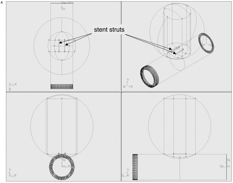
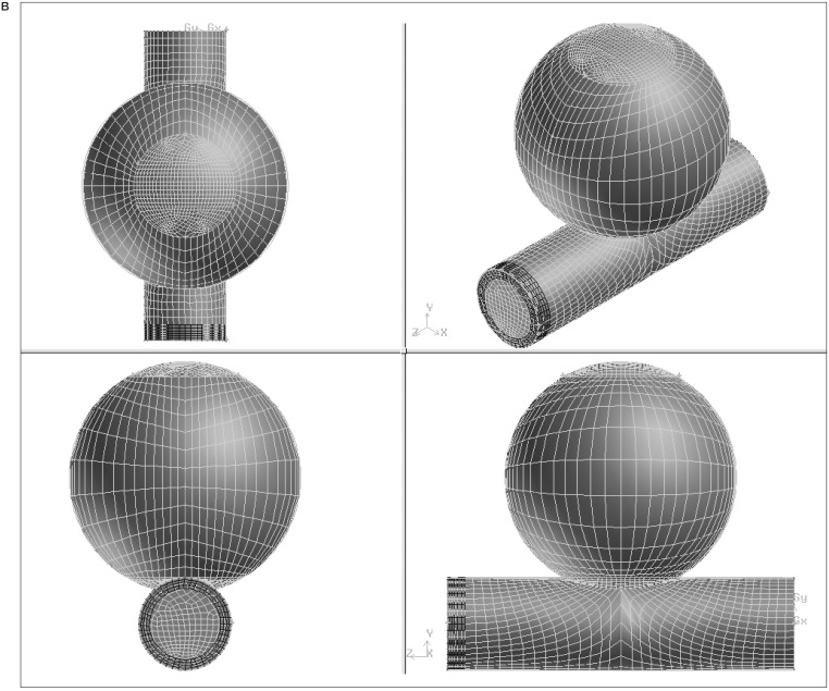
For each combination of strut orientation and separation, the combined vessel and stent geometry was first structured and the computational mesh was created using GAMBIT1.3 (Fluent Inc., Lebanon, NH). An identical process was performed for the vessel model alone, without the inclusion of a stent. The number of mesh elements ranged from 20984 to 24329. figures 1A,B show geometry and mesh for a parallel strut configuration.
Figure 1.
A) Semi-transparent surface display of the aneurysm, parent artery and stent struts and B) the resulting mesh of the model geometry.
For each of the defined geometry prescriptions, the incompressible Navier-Stokes equations were solved using a dedicated, commercially-available Finite Element Method (FEM) flow simulation package (FIDAP 8.6, Fluent Inc., Lebanon, NH) running on a workstation (hp workstation*1100, Pentium 4, 2GHz, 1GB Memory, Hewlett-Packard).
For the simulations, we assumed a steady flow with a mean speed of 290 mm/s, with a velocity of 0 m/s taken as the boundary condition at the vessel wall. The steady viscosity and density were set to 3.83 cp, and 1.0 g/cm3 respectively. The velocity distributions at the aneurysm neck and within the aneurysm were calculated for variable combinations of angles and gaps. Mean values and the histogram for distribution of flow speed were examined and compared for the different configuration. The flow reduction ratio is calculated using the following equation.
To avoid issues related to mesh geometry, the same mesh was used in each study, but the properties of the strut portion were changed to reflect either fluid or strut being present at that position.
Equation
Results
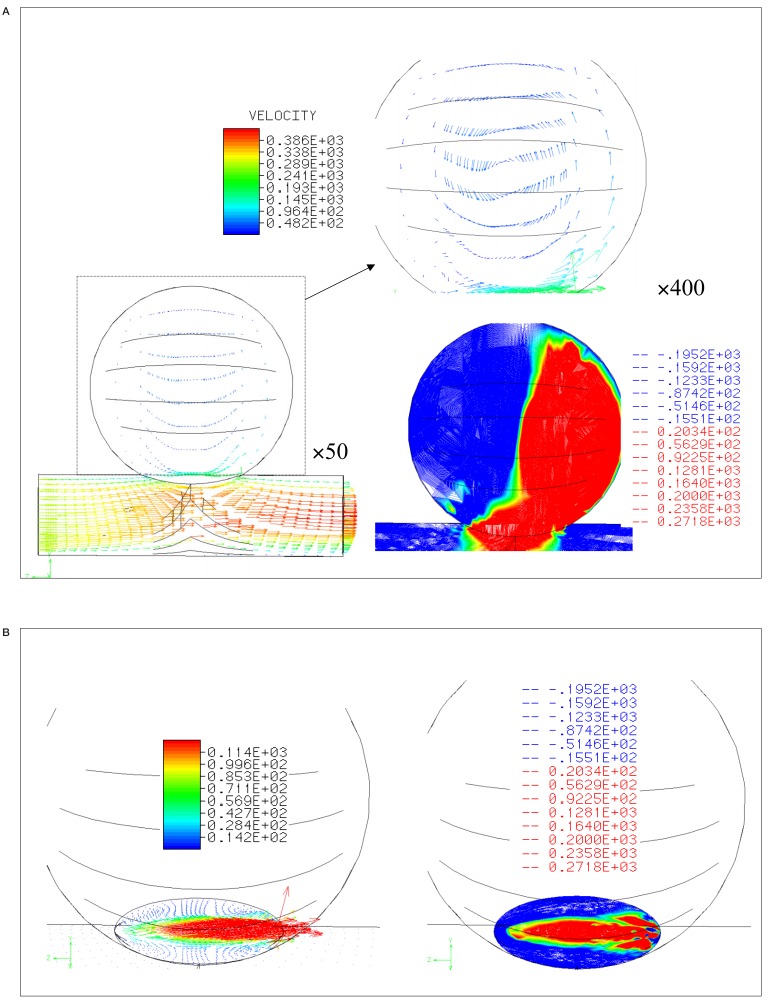
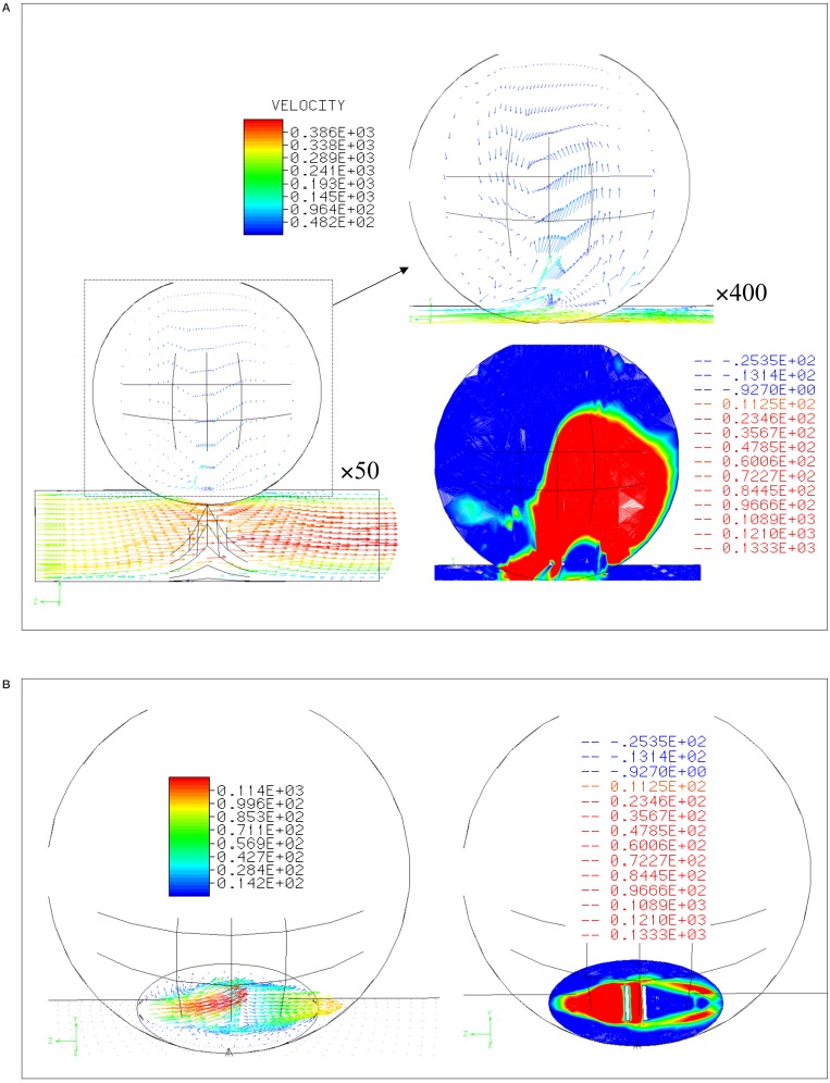
Figure 2A shows a lateral view of the flow in the unstented case, with the flow entering from the left edge of the parent artery. Laminar flow at the outlet and a vortex in the aneurysm are predicted. The flow pattern in the aneurysm was composed of an in-flow zone at the distal neck and an out-flow zone at the proximal neck. These features are better seen in the contour plot of Y-axis speed shown in figure 2B. In the figure of left, arrows express the velocity at the neck, and the speed distribution of the Y-axis is shown in the right image.
Figure 2.
Velocity distribution and contour lines A) within and B) at the neck of aneurysm without stent struts.
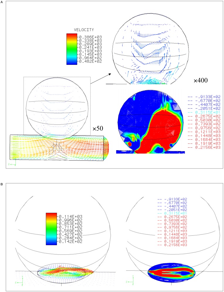
Figure 3 shows a simulation of the flow after a stent is placed with struts parallel to the main axis of the parent artery (strut separation 0.5 mm). Again, the lateral view is seen in figure 3A, and the speed distributions at the neck are shown in figure 3B. The Y-axis speeds are decreased when compared to the pre-stenting. The change of conformation was observed after stenting.
Figure 3.
Velocity distribution and contour lines A) within and B) at the neck of aneurysm with stent struts parallel to the parent artery (0.5 mm separation between the struts).
Figure 4A shows the simulation results for stenting with struts perpendicular to the parent artery (strut separation is 0.5 mm). The strut near to the proximal neck created a division of inflow zone into the aneurysm rather than the parallel struts.
Figure 4.
Velocity distribution and contour lines A) within and B) at the neck of aneurysm with stent struts perpendicular to the parent artery (0.5 mm separation between the struts).
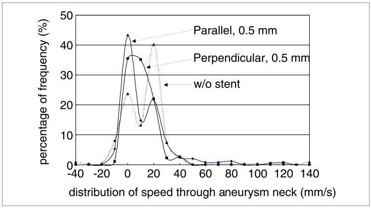
The distribution of flow speeds through the neck of the aneurysm is graphed in figure 5. In the unstented case and that of the parallel strut with 0.5 mm separation, a bilobed distribution is seen with substantial high speed components. The perpendicular stent case is more unilobear with reduced high velocity components.
Figure 5.
Histogram of speed distribution of flow into the aneurysm at the neck.
Within the aneurysm, the average, maximum, and standard deviation (S.D.) of the speed were all reduced by the introduction of stent. All these metrics of the velocity showed greater reduction with perpendicular strut than parallel (table 1). The maximum speed decreased by at least half with stenting, and struts perpendicular to the vessel axis produced a greater reduction than did parallel struts.
Table 1.
Average speed in the aneurysm, the standard deviation (S.D.), and maximum speed of without (w/o) stent, parallel struts and perpendicular struts with 0.5 mm strut separation
| Stent | Average (mm/s) | S.D. | Maximum Speed (mm/s) |
|---|---|---|---|
| w/stent | 32,15 | 28,58 | 560,03 |
| Parallel stent | 22,81 | 17,66 | 238,99 |
| Perpendicular | 21,37 | 15,62 | 159,89 |
The separation of the stent inversely related to the reduction in mean velocity within aneurysm (table 2). Expressed as a ratio of the values obtained in the unstented case, the reduction in the mean of flow speed ranged between 25-36%.
Table 2.
The reduction ratios of after stenting with variation of strut distance from 0.5 mm to 1.5 mm
| Direction of Struts | Distance of Struts (mm) | Reduction Ratio (%) |
|---|---|---|
| Parallel | 0,5 | 25,13 |
| 1,0 | 36,15 | |
| 1,5 | 33,67 | |
| Perpendicular | 0,5 | 28,05 |
| 1,0 | 32,15 | |
| 1,5 | 33,70 | |
Discussion
In this study, we used FEM to investigate the impact of different strut separation distances and strut orientations relative to the parent artery on flow through the aneurysm neck for stents placed across the neck of cerebral aneurysm. The flow pattern in the native aneurysm was composed of an inflow zone at the distal edge of the aneurysm neck, and an outflow zone at the proximal edge, with rotation centered within the aneurysm. This flow pattern is consistent with previously reported computer simulations and in-vitro models12,17,18.
We found perpendicular struts to more effectively decrease flow speed through the aneurysm neck than did the parallel struts, extending the results of Aenis et Al 12 showed that struts perpendicular to the parent vessel axis led to a decrease in the flow speeds within the aneurysm after stenting.
Hirabayashi et Al 13,15,16 characterized the effect of stents on flow speed, and indicated stent position as a factor influencing flow speed.
The simulations do not however distinguish the operative mechanisms that lead to the reduction in flow speeds and the differences arising due to strut orientation and spacing. We sug gest two possible mechanisms. First, the struts act as a boundaries cutting the aneurysm neck into (in these simulations) three zones (vessel wall to strut, strut to strut, and strut to vessel wall).
In the case of struts parallel to the vessel axis, they may act as sidewalls, which maintain the primary proximal and distal conformation of the native aneurysm vortex, but restrict the area open to flow, and thus via viscous effects reduce the velocities achieved. When the struts are perpendicular to the main vessel axis, three successive distal and proximal zone pairs arise, each likely to generate a vortex. This conformation positions the first vortex's inlet zone next to the outlet zone for the second vortex (and similarly for the second inlet and third outlet). As a result the vortices may produce partial cancellation of the overall flow pattern in addition to the increased viscous effects due to the boundary effect of the struts themselves. In addition, a second, smaller effect may arise due to the effect of the struts on flow momentum. With struts parallel to the flow, angle of incidence of fluid striking the struts is likely to be small (low cross-section) and so there is little change to the momentum vector which maintains its speed and direction along the parent artery.
In contrast however, with the struts are perpendicular to the flow, they will present a greater cross-section to the flow, and result in a change in the momentum of fluid striking them, inducing disturbance in the parent and intra-aneurysmal flows. Moreover, the flow pattern or speed distribution at the neck may have good relation to those at the whole neck.
We note that, since only the distance between struts and the strut angle relative to the parent artery were varied, all patterns have the same porosity. Nonetheless, the histograms of the speed distributions differ despite the common porosity of all the strut patterns. This indicates the importance of the design of a stent in defining their effect the flow in aneurysm.
As with any modeling study a number of simplifications were made. The assumption of a rigid vessel is probably acceptable as intracranial arteries and aneurysms are less distensible than extracranial arteries 19-22. While a pulsatile flow was not used in this study, and so the temporal evolution of haemodynamic parameters over the cardiac cycle has been sacrificed, Yu et Al17 and Steiger et Al23 have previously shown, the flow field of a steady flow matches well with the systolic field under the pulsatile conditions.
As regards the idealized 3-D geometry and the simple stent "design". It is certainly desirable to perform simulations on patient specific 3-D geometric data with real stent geometry. Recent reports by Steinman et Al10 and Hassan et Al11 have demonstrated the feasibility of performing CFD simulations based on the 3-D angiographic data of individual patients. It anticipated that advances in computer performance will ultimately lead to that goal for stent studies. Despite the simplifications in the present study, defining the role of stent struts on haemodynamics using an ideal geometry, for which flow has been already investigated with physical models, is a helpful check on the validity of the results to be obtained in later patient-based studies.
Conclusions
Application of finite element methods to the analysis of blood flows in cerebral aneurysm has advanced considerably in the last decade. We have defined a simple model consisting of an aneurysm and a parent artery into which stent struts can be integrated, and a hexagonal computational mesh generated for FEM simulation of the effect of stents on flow in aneurysms. Without stent emplacement, the flow pattern in this aneurysm model consisted of an inflow zone at the distal neck, an out-flow zone at the proximal neck and a vortex within the aneurysm.
The placement of stent struts at the aneurysm neck resulted in a decrease in the mean speed in the aneurysm, regardless of the orientation and separation of the struts. The degree of reduction and the distribution of flow through the neck however did depend on the orientation of the stent struts.
Acknowledgement
This work was supported by the Japanese Association for the Advancement of Medical Equipment, COOK-WCE, and Philips Medical Systems. We are grateful to Dr Paul Summers, Nuffield Department of Surgery, University of Oxford for his assistance in preparing the manuscript.
References
- 1.Molyneux A, Kerr R, et al. International Subarachnoid Aneurysm Trial (ISAT) of neurosurgical clipping versus endovascular coiling in 2143 patients with ruptured intracranial aneurysms: a randomised trial. Lancet. 2002;360:1267–1274. doi: 10.1016/s0140-6736(02)11314-6. [DOI] [PubMed] [Google Scholar]
- 2.Wiebers DO, Whisnant JP, et al. Unruptured intracranial aneurysms: natural history, clinical outcome, and risks of surgical and endovascular treatment. Lancet. 2003;362:103–110. doi: 10.1016/s0140-6736(03)13860-3. [DOI] [PubMed] [Google Scholar]
- 3.Lylyk P, Cohen JE, et al. Endovascular reconstruction of intracranial arteries by stent placement and combined techniques. J Neurosurg. 2002;97:1306–1313. doi: 10.3171/jns.2002.97.6.1306. [DOI] [PubMed] [Google Scholar]
- 4.Geremia G, Haklin M, Brennecke L. Embolization of experimentally created aneurysms with intravascular stent devices. Am J Neuroradiol. 1994;15:1223–1231. [PMC free article] [PubMed] [Google Scholar]
- 5.Rhee K, Han MH, Cha SH. Changes of flow characteristics by stenting in aneurysm models: influence of aneurysm geometry and stent porosity. Ann Biomed Eng. 2002;30:894–904. doi: 10.1114/1.1500406. [DOI] [PubMed] [Google Scholar]
- 6.Lieber BB, Gounis MJ. The physics of endoluminal stenting in the treatment of cerebrovascular aneurysms. Neurol Res. 2002;24(Sup 1):S33–42. doi: 10.1179/016164102101200014. [DOI] [PubMed] [Google Scholar]
- 7.Wakhloo AK, Lanzino G, et al. Stents for intracranial aneurysms: the beginning of a new endovascular era? Neurosurgery. 1998;43:377–379. doi: 10.1097/00006123-199808000-00126. [DOI] [PubMed] [Google Scholar]
- 8.Liou TM, Chang WC, Liao CC. Experimental study of steady and pulsatile flows in cerebral aneurysm model of various sizes at branching site. J Biomech Eng. 1997;119:325–332. doi: 10.1115/1.2796097. [DOI] [PubMed] [Google Scholar]
- 9.Hamuro M, Palmaz JC, et al. Influence of stent edge angle on endothelialization in an in vitro model. J Vasc Interv Radiol. 2001;12:607–611. doi: 10.1016/s1051-0443(07)61484-5. [DOI] [PubMed] [Google Scholar]
- 10.Steinman DA, Milner JS, et al. Image-based computational simulation of flow dynamics in a giant intracranial aneurysm. Am J Neuroradiol. 2003;24:559–566. [PMC free article] [PubMed] [Google Scholar]
- 11.Hassan T, Ezura M, et al. Computational simulation of therapeutic parent artery occlusion to treat giant vertebrobasilar aneurysm. Am J Neuroradiol. 2004;25:63–68. [PMC free article] [PubMed] [Google Scholar]
- 12.Aenis M, Stancampiano AP, et al. Modeling of flow in a straight stented and nonstented side wall aneurysm model. J Biomech Eng. 1997;119:206–212. doi: 10.1115/1.2796081. [DOI] [PubMed] [Google Scholar]
- 13.Hirabayashi M, Ohta M, et al. Characterization of flow reduction properties in an aneurysm due to a stent. Phys Rev E Stat Nonlin Soft Matter Phys. 2003;68:021–918. doi: 10.1103/PhysRevE.68.021918. [DOI] [PubMed] [Google Scholar]
- 14.Washizu H, H. M, Y. Y, Y. Y, T. K. Handbook of Finite Element Method I, Basic part, in Handbook of Finite Element Method. Tokyo: BAIFUKAN CO, LTD; 1981. [Google Scholar]
- 15.Hirabayashi M, Ohta M, et al. A lattice boltzmann study of blood flow in stented aneurysms. FGCS. 2003 [Google Scholar]
- 16.Hirabayashi M, Ohta M, et al. Lattice boltzmann analysis of the flow reduction mechanism in stented cerebral aneurysms for the endovascular treatment. Computational Science-ICCS. 2003;2657:1044–1053. [Google Scholar]
- 17.Yu SC, Zhao JB. A steady flow analysis on the stented and non-stented sidewall aneurysm models. Med Eng Phys. 1999;21:133–141. doi: 10.1016/s1350-4533(99)00037-5. [DOI] [PubMed] [Google Scholar]
- 18.Gobin YP, Counord JL, et al. In vitro study of haemodynamics in a giant saccular aneurysm model: influence of flow dynamics in the parent vessel and effects of coil embolization. Neuroradiology. 1994;36:530–536. doi: 10.1007/BF00593516. [DOI] [PubMed] [Google Scholar]
- 19.Steiger HJ, Aaslid R, et al. Strength, elasticity and viscoelastic properties of cerebral aneurysms. Heart Vessels. 1989;5:41–46. doi: 10.1007/BF02058357. [DOI] [PubMed] [Google Scholar]
- 20.Canham PB, Ferguson GG. A mathematical model for the mechanics of saccular aneurysms. Neurosurgery. 1985;17:291–295. doi: 10.1227/00006123-198508000-00007. [DOI] [PubMed] [Google Scholar]
- 21.Foutrakis GN, Burgreen G, et al. Construction of 3-D arterial volume meshes from magnetic resonance angiography. Neurol Res. 1996;18:354–360. doi: 10.1080/01616412.1996.11740436. [DOI] [PubMed] [Google Scholar]
- 22.Scott S, Ferguson GG, Roach MR. Comparison of the elastic properties of human intracranial arteries and aneurysms. Can J Physiol Pharmacol. 1972;50:328–332. doi: 10.1139/y72-049. [DOI] [PubMed] [Google Scholar]
- 23.Steiger HJ, Poll A, et al. Haemodynamics stress in lateral saccula aneurysms. Acta Neurochir (Wien) 1987;86:98–105. doi: 10.1007/BF01402292. [DOI] [PubMed] [Google Scholar]


