

Abstract
Curved surfaces, complex geometries, and time-dynamic deformations of the heart create challenges in establishing intimate, nonconstraining interfaces between cardiac structures and medical devices or surgical tools, particularly over large areas. We constructed large area designs for diagnostic and therapeutic stretchable sensor and actuator webs that conformally wrap the epicardium, establishing robust contact without sutures, mechanical fixtures, tapes, or surgical adhesives. These multifunctional web devices exploit open, mesh layouts and mount on thin, bio-resorbable sheets of silk to facilitate handling in a way that yields, after dissolution, exceptionally low mechanical moduli and thicknesses. In vivo studies in rabbit and pig animal models demonstrate the effectiveness of these device webs for measuring and spatially mapping temperature, electrophysiological signals, strain, and physical contact in sheet and balloon-based systems that also have the potential to deliver energy to perform localized tissue ablation.
Keywords: flexible electronics, semiconductor nanomaterials, stretchable electronics, implantable biomedical devices, cardiac electrophysiology
Cardiac arrhythmias occur in all component structures and 3D regions of the heart, resulting in significant challenges in diagnosis and treatment of precise anatomic targets (1). Many common arrhythmias, including atrial fibrillation and ventricular tachycardia, originate in endocardial substrates and then propagate in the transverse direction to affect epicardial regions (1, 2). Characterizing arrhythmogenic activity at specific regions of the heart is thus critical for establishing the basis for definitive therapies such as cardiac ablation (3). Advanced tools that offer sufficient spatial resolution (<1 mm) and intimate mechanical coupling with myocardial tissue, but without undue constraints on natural motions, would therefore be of great clinical importance (4–6). To date, cardiac ablation procedures have largely relied on point ablation catheters deployed in the endocardial space (1, 5, 7–9). Although successful in the treatment of simple arrhythmias originating in and around the pulmonary veins, these devices are poorly suited for treating complex arrhythmias, such as persistent atrial fibrillation (10–13), that arise from various sites inside the left atrium. Other classes of devices have demonstrated the utility of spatiotemporal voltage mapping using various modes of operation, including noninvasive surface mapping designs (14, 15), epicardial voltage-mapping “socks” (16–20), and endocardial contact and noncontact catheters, with densities approaching 64 electrodes (21–31). These solutions all exploit arrays of passive metal wire-based electrodes integrated on wearable vests and socks (14–20) or catheter systems (21–26) for mapping of complex arrhythmias. Building such mesh structures requires manual assembly and is only possible because the individual wires are millimeter scale in diameter and thus sufficiently large to be threaded to form a mesh. For catheter systems, the large size of individual electrodes gives rise to scalability challenges and interfacial mismatches between the mechanical properties and density of conventional passive electrode formats and that of soft, deformable cardiac tissue. Moreover, passive wire electrodes are largely limited to electrical sensing, without providing simultaneous feedback about mechanical and thermal properties; they are also incapable of providing more advanced forms of functionality that demand semiconductor devices as sensors or processing elements.
A much more powerful approach would exploit full, integrated circuits in intimate contact with the affected regions for evaluation in a parallel mode, at high sampling rates and high resolution, providing direct insight into the complex electrical, mechanical, and thermal properties of cardiac structures at the cellular level. The practical challenge is in interfacing the hard, planar forms of electronics that exist today with the soft, curvilinear, and time-dynamic surfaces of the heart, in a way that provides intimate, nondestructive contact, without slippage at the biotic/abiotic interface. Recent advances in nanomaterials research have established versatile strategies in mechanics designs and manufacturing techniques for high-quality electronics that can flex, twist, and stretch in ways that facilitate integration with biology (32). The most basic of these technologies (6, 33) was recently demonstrated in thin, flexible sheets of electronics that laminate on certain areas of the heart to provide unmatched capabilities in electrophysiological mapping. Although this format is effective for measuring small regions or those with modest curvature, it is incapable of large-scale evaluation or integration with epicardial areas around the apex or in structured regions across the atrioventricular groove between the ventricles, owing to the inability of flexible sheets to wrap and conform to the complex topographies of the heart. Complex endocardial surfaces within the atria and ventricles pose even greater challenges for intimate soft contact.
Ultra-low modulus, stretchable sensor and actuator webs overcome the limitations of previously described cardiac and brain mapping sheets to allow intimate integration with the skin, even on highly irregular, wrinkled regions (34). In this case, a soft elastomeric film provides a supporting substrate in an overall design that offers equivalent mechanical properties that are matched to epidermis. The ability to conform to a dynamically deforming substrate like the heart poses significant new challenges compared with the brain and skin, which undergo significantly smaller levels of continuous deformations than the heart. Straightforward use of this technology for cardiac applications is thus frustrated, both by the highly time-dynamic motions associated with beating of the heart and by the need to wrap substantial regions of its surface. The biology itself (i.e., the heart) might, however, have the capacity to serve as the stretchable substrate in a manner similar to the static surface of the brain (35).
In this article we report a class of electronics that adopts this design in the form of epicardial webs, to provide (i) exceptionally low effective stiffness and high degrees of deformability, to yield negligible mechanical constraints on the natural motions of the heart and an ability to wrap large areas and complex contours, (ii) robust adhesion of sensor and actuator devices (located at the nodes of the mesh) to the epicardial surface simply by capillary interactions associated with the moist surface of the tissue, even under full dynamic motion associated with beating, (iii) open access of the vast majority of the tissue for introduction of bio-fluids, drugs, or other device probes, and (iv) direct visual and optical interrogation, for spectroscopic and/or microscopic measurement. The following results demonstrate this technology in a collection of sensor arrays that can measure electrical activity, temperature, mechanical strain, pressure, and physical contact on sheet and balloon-based platforms. Detailed modeling of the mechanics and in vitro and in vivo evaluations on animal models illustrate the underlying physics and potential clinical utility.
Results and Discussion
The web incorporates interconnects with filamentary serpentine shapes that join small sensor or actuator pads, all with ultrathin construction (<5 μm) and neutral mechanical plane configuration. Fig. 1 A–C shows designs and pictures of a representative epicardial web for electrophysiological mapping. The fabrication involves microelectronic processing techniques to create patterns of sensors and actuators that are lifted onto a sacrificial silk film and mounted onto the surface of the heart (Fig. 1 D–F). The silk film dissolves within minutes after exposure to moisture, leaving the web as a conformal, functional laminate on the heart. The systems stretch to ∼20% or more with minimum mechanical resistance (Fig. 1C).
Fig. 1.

Sensor web designed for epicardial EGM mapping. (A) Layout (Left) and corresponding picture (Right) of a web. (Insets) Magnified views of a pair of electrodes. (B) Optical image of a web after lamination onto tissue followed by dissolution of the silk substrate (Upper) and in free-standing form in a stretched configuration (Lower). (C) In vitro stretching experiment of a web on chicken meat with no slippage up to ∼22% strain. (D) Web on a silk substrate and after mounting on the epicardial surface (E). (F) Magnified image of interconnected electrodes moving synchronously with the underlying tissue. (G) Recorded EGM from electrodes during normal rhythm (Left), rapid pacing at ∼200 bpm (Center), and during tachycardia (Right). (H) EGM activation mapping at several time intervals, showing a depolarization wave front. The right frame provides color scales for potentials.
Measurement of differential bipolar potentials during movements of the heart demonstrates essential functions in locating arrhythmogenic activity (Fig. 1 G and H). Rapid motions associated with cardiac contraction exert lateral forces on the web but cause little change in electrical performance because of the ability of the structures to naturally couple with the underlying cardiac tissue (Fig. 1 E and F). Surface tension due to tissue hydration provides further mechanical stability to ensure that the measuring sensors maintain contact at fixed positions. In vitro stretching experiments on centimeter-scale segments of muscle tissue excised from chicken (Gallus gallus domesticus) torso show minimal slipping of devices relative to the tissue, in response to ∼22% applied strains (Fig. 1C). Detailed layouts, cross-sectional designs, and fabrication strategies are provided in SI Appendix and Fig. S1. The same basic concepts and procedures may be used for diverse classes of sensors, as described in the next section.
Quantitative mechanics models (SI Appendix, Fig. S2) guide choices of web layout according to the elastic properties of the soft tissue and the nature of the interfacial contact. Three issues are of primary importance: (i) the effective stiffness of the web, (ii) the static adhesion forces that drive its conformal contact with the tissue, and (iii) interfacial friction forces that limit slippage of the nodes across the epicardial surfaces during motion. First, the tensile ( ) and bending stiffness (
 ) can be obtained analytically in terms of the island and interconnect material properties and geometric configuration (SI Appendix, Fig. S1C). In particular, for the devices of Fig. 1, analysis yields
  = 16 N/m and
  = 0.33 nN-m, in good agreement with finite element analysis (FEA). Furthermore,
  is reduced even further to values as low as 0.01 N/m, upon noncoplanar buckling of interconnects, as in SI Appendix. These values are exceptionally small compared with cardiac tissue, which has
  = 76 N/m and
  = 23 μN-m for 1.9-mm-thick ventricular walls (36) and an elastic modulus of Eheart = 40 kPa (37). By comparison with previously reported active cardiac and neural mapping sheets [bending stiffness 31 N-m (6)], the web devices presented in this study are 5 orders of magnitude softer and comparable to passive devices used on the brain (34).The most favorable epidermal electronics had values of
  = 4.2 N/m and
  = 0.3 nN-m (35). The peak strains in webs during motion are also exceptionally small. For a full cycle of contraction to expansion during normal beating of the heart (∼10% strain in both directions; SI Appendix, Fig. S2C), FEA gives maximum strains of 0.12% and 0.0091% in the polyimide and gold layers of electrodes and interconnects (SI Appendix, Fig. S2 D and E), with no slippage of the web on the heart.
The second mechanics issue relates to intimate coupling between electrodes (widths of L × L) and the heart, approximated as a sphere with radius Rheart. For stable wrapping, the adhesion energy must overcome the increase in elastic energy due to global deformation of the web. This criterion can be described by the following analytical form (SI Appendix,Eq. S1):
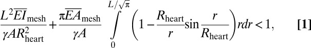 |
where γ and A are the work of adhesion and contact area between arrays and the moist surface of the heart, respectively. For experimental data of L = 20 mm, Rheart ∼ 25 mm, γ ∼ 0.1 N/m (38–40), A = 125 mm2 and the calculated  (∼16 N/m) and
  above, the left-hand side of Eq. 1 (∼0.01) is 2 orders of magnitude smaller than 1. Consequently, the web should maintain good conformal contact with the heart during expansion and contraction (∼10% change in Rheart).
Locally, electrode islands are in a periodic arrangement (Fig. 1 A and B). The energy release rate G for interfacial bonding between islands and a deforming substrate is given by (41) (SI Appendix):
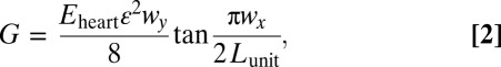 |
where ε ∼ ±10% is the approximate maximum expansion/contraction of the heart, Eheart is the Young’s modulus of the heart, Lunit is the length of a representative unit cell of the electrode array (SI Appendix, Fig. S2C), and wx and wy are sizes of the island (SI Appendix, Fig. S2C). Electrode islands will remain intact with the heart during beating, provided that G < γ, where γ ∼ 0.1 N/m (38–40) is the interfacial work of adhesion between the electrode and the heart. For experimental data of wx = 560 μm, wy = 290 μm, Lunit = 1.0 mm, Eq. 2 gives G = 0.022 N/m, which is smaller than γ, and therefore, locally, there is no delamination between islands and the heart surface. For a larger stretch of ε ∼ 20% as in Fig. 1C, G = 0.088 N/m given by Eq. 2 is still smaller than the interfacial adhesion, consistent with experiments (no interfacial delamination).
The third aspect relates to dynamic frictional forces at the interface, and their critical role in preventing relative slip of sensor/actuator nodes on the heart during beating. Webs expand/contract during heart motion, depending on the ability of interconnects to stretch and compress. The resulting maximum force acting on each island is obtained as 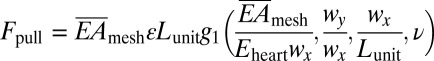 by considering equilibrium between the island, interconnect, and the heart, where the function g1 is given analytically in SI Appendix, ν is the Poisson’s ratio of the heart. Because the web mounts on the epicardial surface without adhesives, the cumulative interface frictional force can be considered as the sum of such forces at each electrode, f = μ⋅pair⋅wx⋅wy, where μ is the coefficient of friction and pair is the atmospheric pressure. To avoid slipping, Fpull
< f, in other words,
by considering equilibrium between the island, interconnect, and the heart, where the function g1 is given analytically in SI Appendix, ν is the Poisson’s ratio of the heart. Because the web mounts on the epicardial surface without adhesives, the cumulative interface frictional force can be considered as the sum of such forces at each electrode, f = μ⋅pair⋅wx⋅wy, where μ is the coefficient of friction and pair is the atmospheric pressure. To avoid slipping, Fpull
< f, in other words,
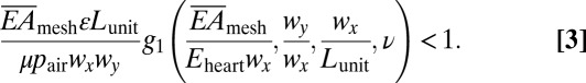 |
The experimental parameters are pair = 1.0 atm, wx
× wy = 560 × 290 μm2, Lunit = 1.0 mm, and ν = 0.45 (37). Literature reports suggest that μ ∼ 1.6 with certain values that are an order of magnitude smaller (42). Eq. 3 holds over this range such that the electrode array does not slide because buckling of interconnects exerts much smaller pulling force on islands. With these values and  = 16 N/m (before the interconnects buckle), the left-hand side of Eq. 3 (∼0.05) is roughly 20 times lower than 1, indicating that slip effects are marginal during the beating cycle of the heart. This prediction is consistent with experimental findings (Fig. 1C) with no slippage up to ∼22% strains, limited only by damage in tissues at higher strains.
Electrogram (EGM) recordings from the anterior ventricular surfaces validate the favorable mechanics and interface properties of the web design. Images collected during cardiac contractions (Fig. 1 E and F) show ∼10% strains, without any noticeable slippages. Fig. 1G shows EGMs recorded from bipolar electrodes during normal rhythm [∼120 beats per minute (bpm), Left], external pacing (∼200 bpm, Center), and during abnormal rhythms (tachycardia, Right). The differential potentials measured across multiple electrodes can be converted into voltage color maps to reveal activation patterns using the onset and timing of activation across multiple sensors spaced across ∼2 cm2 surface (Fig. 1H). Although it is difficult to assess directionality of wave fronts as in optical mapping in vitro studies, webs containing 17 electrodes over the anterior surface of the heart were sufficient for isopotential voltage maps in vivo. We applied Delaunay triangulation to fit a surface to the electrode potentials measured across the array. The surface passed through the midpoint of each bipolar electrode and was linearly interpolated between individual nodes. Alternatively, single-ended voltage recordings and their differentials could provide further insight into activation patterns and directionality of wave fronts (43). These cardiac webs can be fabricated with dimensions suitable to characterize electrical activity of significantly larger human hearts by using similar procedures, but implemented with modern silicon (Si) foundries (12 in Si wafer technology) or flat panel display (glass substrate) manufacturing strategies. The number of wires for addressing the sensors may also be minimized via multiplexing schemes that exploit Si nanomembrane (NM) transistors as switching elements (6, 33).
In addition to electrical mapping, temperature sensors with similar designs can be used to map thermal activity during radiofrequency (RF) and cryo-ablation. Thermal and electrical activity monitoring during the delivery of pacing and ablation energy are powerful capability sets, that when offered in a single platform could enhance the safety and efficacy of cardiac ablation. Local EGM mapping reveals the electrical activity at a specific anatomical target and mapping of temperature distribution during energy delivery, then ensures adequate lesion characterization laterally and in the transverse directions. This form of thermography in epicardial web formats provides useful functionality to assess lesion formation. The same design strategies that apply to EGM electrodes are relevant to microfabricated thermistor arrays consisting of Ti/Pt (5/50 nm) thermal detectors (Fig. 2 A and B and SI Appendix, Fig. S3). Minimal leakage current in saline solution validates the reliability of encapsulation schemes (SI Appendix, Fig. S4). A ∼40-mm2 cylindrical section (radius ∼3.5 mm) of dry ice placed on the center of the array and then removed after ∼2.4 min simulates a cryoablation event, as illustrated by the dotted circle in Fig. 2B. RF energy delivered by a point electrode located near the array of temperature sensors demonstrates functionality in this context. Images of resulting lesions for each process appear in Fig. 2C. Calibration results of temperature sensors appear in Fig. 2D (normalized R, i.e., R/R0) and Fig. 2D, Inset (raw R, i.e., R), respectively. Fig. 2E shows the changes in temperature measured at individual sensor nodes during cryoablation. Sensors located close to the source register temperatures as low as −48 °C (Fig. 2E); those at millimeter distances show higher temperatures. More details for thermal sensing capability are in SI Appendix.
Fig. 2.

Stretchable temperature sensor web to monitor cryo- and RF ablation. (A) Sensor web, with Inset of a magnified view of a temperature sensor. Four locations, denoted by #1 to #4, were monitored during cryo-ablation. (B) Sensor web on a silk substrate. Dry ice caused cryo-lesions when in direct contact with the epicardial surface (white dotted circle) for ∼1 min. (C) Image of temperature sensor web on the epicardial surface (Upper Left) and lesions formed by cryo-ablation (Upper Right) and RF ablation (Lower). (D) Calibration curve for temperature sensors, showing normalized resistance at each temperature. (Inset) Raw temperature data. (E) Temperature change as a function of time during dry ice application. (F) Computed temperature distribution during cryo-ablation.
Models of heat conduction can determine expected temperature distributions (SI Appendix, Fig. S5A). The ventricular wall of the rabbit heart has a nominal thickness h = 1.9 mm, thermal conductivity k = 0.512 W/m/K (44), and a thermal diffusivity α = 0.131 mm2/s (45). Computed variations in surface temperature are consistent with experimental findings over the entire time range (∼3 min) without parameter fitting (SI Appendix, Fig. S5B). At t = 2.4 min, the temperature exceeds that for successful lesion (∼−50 °C) over a region with diameter ∼8.2 mm and depth ∼1.9 mm around the dry ice (Fig. 2F). The same device can also monitor elevated temperatures in RF ablation (SI Appendix, Fig. S6A). The model predicts temperature distributions that are in good agreement with measurement (SI Appendix, Fig. S6B). The ability to track localized tissue temperatures during both cryo- and RF ablation could provide clinicians with improved accuracy and control in targeting and ablating aberrant electrical foci, resulting in improved treatment.
In addition to temperature profiles, similar classes of webs, when firmly bonded to thin (∼300 μm) soft (Young’s modulus ∼60 kPa) sheets of silicone (Ecoflex 0030) can spatially map mechanical strain distributions, providing critical intraprocedural insight into mechanical contractions of the heart and shifts in heart rate during sinus and arrhythmic rhythm. The key advantage of real-time strain sensing over competing imaging analysis techniques like MRI is in the intraprocedural mode of use, which enables physicians to track sudden shifts in local contractions as they occur. Technologies, ranging from metal wires to Si plates and mercury-in-rubber structures, have been used for monitoring strain in various parts of the body (46–48), but none offers the combination of characteristics needed for epicardial applications. Ultrathin Si NM (49) configured into piezoresistors as narrow strips in rosettes with longitudinal, diagonal, and transverse orientations provide a solution, incorporated into the web platform (Fig. 3 A and B, SI Appendix, and SI Appendix, Fig. S7) Information on related flexible devices appears elsewhere (50). Mounting such strain-sensing webs on ∼0.3-mm-thick silicone substrates finalizes the fabrication (Fig. 3C and SI Appendix). Subjecting the substrate to uniaxial tension induces changes in resistance, as plotted in SI Appendix, Fig. S8 A and B. The effective gauge factor is defined as GF = GFSi × εg/εa, where GFSi = 100 is the intrinsic gauge factor of single crystalline, εg is the average strain in the gauge, and εa is the applied strain. Mechanics modeling (SI Appendix) gives analytically εg for the longitudinal gauge and therefore the effective GF is obtained as:
 |
where (EA)g, Lg, and wg are the tensile stiffness, length, and width of the gauge, respectively; Esilicone and νsilicone are the Young’s modulus and Poisson’s ratio of the silicone; and the function g2 is given analytically in SI Appendix. Using experimental data of (EA)g = 1.6 N, Esilicone = 200 kPa, νsilicone = 0.48, Lg = 0.48 mm, wg = 80 μm, Eq. 4 gives GF = 0.22, which agrees well with effective GF of 0.23 measured in experiments. This value is much smaller than GFSi, as expected owing to the huge elastic mismatch between Si NM resistor and the substrate (51). The transverse gauge experiences compression due to the lateral contraction of the substrate that results from the Poisson effect; its resistance decreases. The diagonal gauge does not deform significantly; its response is, therefore, negligible. These results can be verified quantitatively by FEA in Fig. 3D. A silicone sheet bonded to a group of strain rosettes is stretched along direction 2 by 10%. Contour plots of longitudinal strain in direction 2 (ε22) of silicone substrate and Si NMs appear in Fig. 3D, Left and Center. The average tensile strain in the longitudinal resistor is only 0.023% when the substrate is stretched by 10%, resulting in GF = 0.23 according to Eq. 4. Fig. 3D, Right shows the contour plots of strains in direction 1 (ε11, i.e., transverse strain) in the Si NMs. The average strain in the transverse resistor is −0.0070% after 10% longitudinal stretch, resulting in a 0.70% decrease in resistance. As shown in Fig. 3D, Center and Right, strains in the diagonal resistor approach zero (zero resistance change).
Fig. 3.

Fabrication, characterization, and modeling of Si NM strain gauge webs. (A) Optical image of array of strain gauges on a handle wafer. (B) Enlarged view of the red dotted box showing one of eight strain rosettes with longitudinal, diagonal, and transverse Si NM piezoresistors. (C) Optical image of array of eight stretchable strain rosettes on 0.3-mm-thick silicone substrate. (D) Strain distribution in silicone and a Si NM, induced by 10% uniaxial tensile strain. (Left)The longitudinal strains (ε22) in the silicone are uniformly distributed (near 10%) except for the area covered by a longitudinally oriented Si NM; (Center) the ε22 in the Si NM are three orders of magnitude smaller than the applied strain; (Right) the transverse strains (ε11) in the transverse Si NM are negative owing to the Poisson’s effect in the silicone. (E) In vivo test on the beating rabbit heart.
Applying such soft and stretchable strain gauges to a beating heart reveals strain patterns associated with expansion/contraction (Fig. 3E). Peak-to-peak strains were 5%∼15%, depending on the location of the devices on the heart. Systolic strains obtained in this study agree with those obtained by MRI (52) and by FEA (53). Comparing the strain results before and after pacing, we notice that pacing alters the frequency but not the amplitude. However, by comparing the strain results before and after ischemia, we see changes in both frequency and amplitude. Reduced cardiac output caused by ischemia slows down the normal rhythm and also significantly reduces the amplitude, thereby providing insight into the progression of disease states.
As a final demonstration, we illustrate tactile sensing, integrated on the surfaces of collapsible balloon catheters that undergo extreme mechanical deformations during use. For high-efficacy ablation, it is important to establish full, conformal contact with the endocardial surface to eliminate the heat sink caused by blood flow around the surface of the balloon. As a demonstration of a technology that can assess contact in the context of this need, we integrated microelectrodes on the surface of the balloon as a way to capture mechanical interactions at the balloon–tissue interface, through measurements of electrical impedance. To date, X-ray imaging has been the most widely used tool to assess contact. However, X-ray exposure has harmful health side effects, necessitating new routes to limit exposure during ablation procedures (54). Fig. 4 A and B provides images of a representative balloon catheter with impedance-based devices, positioned slightly distal to the equator (SI Appendix), in its inflated and deflated state (for a cardiac web deployed by catheter in a cardiac chamber, Fig. 4C). Alternative classes of sensors with related functionality using conductive-silicone pads were reported previously (55). Although these devices provide quantitative measures of pressure, they involve a thick, multilayer construction (∼30 μm), susceptible to mechanical damage during deployment and use. Impedance-based sensors, with simple and thin profiles (<5 μm), offer high sensitivity, fast response, and EGM mapping ability. Here, we inject small amounts (<10 μA) of alternating current across two terminals and measure voltage changes caused by differences in conductivities of surrounding media. To test this sensor concept on balloons, impedance differences between excised chicken muscle tissue and saline solution were first tested in vitro. The results show definitive shifts in impedance during on/off contacts (SI Appendix, Fig. S9). The same impedance-based tactile sensor array was applied to a porcine model for endocardial contact sensing in vivo. The difference in conductivity, σ, between myocardial tissue and blood (factor of ∼2–3) was sufficient to register differences. Fig. 4C shows X-ray images of a representative balloon in the ostium of the superior vena cava. Such images provide real-time poor visual feedback on the state and position of the balloon with respect to the ostia in the atria. Contact with cardiac tissue was detected with high levels of confidence with negligible impedance changes by inflation and deflation of the balloon (Fig. 4D). To measure local contact in other endocardial regions of the heart with complex anatomy, like the ventricles, requires either porous, inflatable mesh substrates with nanomembrane formats embedded on the mesh, or partially space-occupying “wands or leaf-shaped” directable, curved balloons, to facilitate blood flow inside the ventricles during operation.
Fig. 4.

Impedance-based contact sensor webs, on collapsible balloon catheters. (A) Optical image of a device (Left), with magnified view (Right), and picture in its deflated state (B). (C) X-ray image of balloon catheter demonstrating contact and noncontact conditions near the superior vena cava in a live porcine model. (D) In vivo tests impedance contact sensors. Inflation and deflation cycling experiments confirm that sudden increases in impedance coincide with the contact event.
Conclusions
The sensing and actuator webs described here constitute a class of cardiac medical devices suited for capturing physiological data from large areas of beating hearts without imposing significant mechanical loads or inducing any adverse effects during the course of a typical measurement. These systems are significantly softer and thinner than existing devices, and because they exploit modern techniques in semiconductor device fabrication, they are immediately scalable to large areas and large numbers of multifunctional sensors, actuators, and electronics. Materials layouts and mechanics formats guide optimal design configurations that establish strong adhesion at the tissue–device interface, without separate adhesives, thereby providing attractive features for minimally invasive clinical use and for basic research in Langendorff-perfused heart models. Related web systems on catheters and other surgical tools have direct relevance to many implantable cardiac procedures.
Materials and Methods
Detailed fabrication information of EGM webs, temperature sensor and strain gauge webs, and impedance sensors on balloon catheter is shown in SI Appendix. Design of data acquisition system and related hardware is also described in SI Appendix. All animal procedures and experiments were approved by the Institutional Animal Care and Use Committee at the University of Arizona and by the Massachusetts General Hospital Center for Comparative Medicine.
Supplementary Material
Acknowledgments
We thank Roja Nunna and Nishan Subedi for implementation and testing of the data acquisition system, and Behrooz Dehdashti and members of the Sarver Heart Center for help with in vivo animal studies. This material is based on work conducted at the Materials Research Laboratory and Center for Microanalysis of Materials (DE-FG02-07ER46453) at the University of Illinois at Urbana–Champaign. This work was supported by the World Class University (WCU) program through the National Research Foundation of Korea funded by the Ministry of Education, Science and Technology (R31-10013) and the Basic Science Research Program through the Korea National Research Foundation funded by Ministry of Education, Science and Technology Grant 2012R1A1A1004925. J.A.R. has received a National Security Science and Engineering Faculty Fellowship. N.L. receives support from the startup fund from the Cockrell School of Engineering at the University of Texas at Austin.
Footnotes
Conflict of interest statement: R.G., M.J.S., and J.A.R. are co-founders of MC10 Inc.
This article is a PNAS Direct Submission. K.K.P. is a guest editor invited by the Editorial Board.
This article contains supporting information online at www.pnas.org/lookup/suppl/doi:10.1073/pnas.1205923109/-/DCSupplemental.
References
- 1.Calkins H, et al. Heart Rhythm Society European Heart Rhythm Association European Cardiac Arrhythmia Society American College of Cardiology American Heart Association Society of Thoracic Surgeons HRS/EHRA/ECAS expert consensus statement on catheter and surgical ablation of atrial fibrillation: Recommendations for personnel, policy, procedures and follow-up. Europace. 2007;9(6):335–379. doi: 10.1093/europace/eum120. [DOI] [PubMed] [Google Scholar]
- 2.Kléber AG, Rudy Y. Basic mechanisms of cardiac impulse propagation and associated arrhythmias. Physiol Rev. 2004;84(2):431–488. doi: 10.1152/physrev.00025.2003. [DOI] [PubMed] [Google Scholar]
- 3.Kato R, et al. Pulmonary vein anatomy in patients undergoing catheter ablation of atrial fibrillation: Lessons learned by use of magnetic resonance imaging. Circulation. 2003;107(15):2004–2010. doi: 10.1161/01.CIR.0000061951.81767.4E. [DOI] [PubMed] [Google Scholar]
- 4.Aziz JNY, et al. 256-channel neural recording and delta compression microsystem with 3D electrodes. IEEE J Solid-State Circuits. 2009;44:995–1005. [Google Scholar]
- 5.Dewire J, Calkins H. State-of-the-art and emerging technologies for atrial fibrillation ablation. Nat Rev Cardiol. 2010;7(3):129–138. doi: 10.1038/nrcardio.2009.232. [DOI] [PubMed] [Google Scholar]
- 6.Viventi J, et al. A conformal, bio-interfaced class of silicon electronics for mapping cardiac electrophysiology. Sci Transl Med. 2010;2(24):24ra22. doi: 10.1126/scitranslmed.3000738. [DOI] [PMC free article] [PubMed] [Google Scholar]
- 7.Greenspon A. Advances in catheter ablation for the treatment of cardiac arrhythmias. IEEE Trans Microw Theory Tech. 2000;48:2670–2675. [Google Scholar]
- 8.Haïssaguerre M, et al. Spontaneous initiation of atrial fibrillation by ectopic beats originating in the pulmonary veins. N Engl J Med. 1998;339(10):659–666. doi: 10.1056/NEJM199809033391003. [DOI] [PubMed] [Google Scholar]
- 9.Haïssaguerre M, et al. Mapping and ablation of idiopathic ventricular fibrillation. Circulation. 2002;106(8):962–967. doi: 10.1161/01.cir.0000027564.55739.b1. [DOI] [PubMed] [Google Scholar]
- 10.Dong J, Calkins H. Technology insight: Catheter ablation of the pulmonary veins in the treatment of atrial fibrillation. Nat Clin Pract Cardiovasc Med. 2005;2(3):159–166. doi: 10.1038/ncpcardio0137. [DOI] [PubMed] [Google Scholar]
- 11.Haïssaguerre M, et al. Catheter ablation of long-lasting persistent atrial fibrillation: Clinical outcome and mechanisms of subsequent arrhythmias. J Cardiovasc Electrophysiol. 2005;16(11):1138–1147. doi: 10.1111/j.1540-8167.2005.00308.x. [DOI] [PubMed] [Google Scholar]
- 12.Pappone C, Santinelli V. Mapping and ablation: A worldwide perspective. J Interv Card Electrophysiol. 2006;17(3):195–198. doi: 10.1007/s10840-007-9083-3. [DOI] [PubMed] [Google Scholar]
- 13.Wazni OM, et al. Radiofrequency ablation vs antiarrhythmic drugs as first-line treatment of symptomatic atrial fibrillation: A randomized trial. JAMA. 2005;293(21):2634–2640. doi: 10.1001/jama.293.21.2634. [DOI] [PubMed] [Google Scholar]
- 14.Ramanathan C, Ghanem RN, Jia P, Ryu K, Rudy Y. Noninvasive electrocardiographic imaging for cardiac electrophysiology and arrhythmia. Nat Med. 2004;10(4):422–428. doi: 10.1038/nm1011. [DOI] [PMC free article] [PubMed] [Google Scholar]
- 15.Rudy Y. Noninvasive imaging of cardiac electrophysiology and arrhythmia. Ann N Y Acad Sci. 2010;1188:214–221. doi: 10.1111/j.1749-6632.2009.05103.x. [DOI] [PubMed] [Google Scholar]
- 16.Faris OP, et al. Novel technique for cardiac electromechanical mapping with magnetic resonance imaging tagging and an epicardial electrode sock. Ann Biomed Eng. 2003;31(4):430–440. doi: 10.1114/1.1560618. [DOI] [PMC free article] [PubMed] [Google Scholar]
- 17.Harrison L, et al. The sock electrode array: A tool for determining global epicardial activation during unstable arrhythmias. Pacing Clin Electrophysiol. 1980;3(5):531–540. doi: 10.1111/j.1540-8159.1980.tb05272.x. [DOI] [PubMed] [Google Scholar]
- 18.McVeigh E, Faris O, Ennis D, Helm P, Evans F. Electromechanical mapping with MRI tagging and epicardial sock electrodes. J Electrocardiol. 2002;35(Suppl):61–64. doi: 10.1054/jelc.2002.37156. [DOI] [PMC free article] [PubMed] [Google Scholar]
- 19.Sutherland DR, Ni Q, MacLeod RS, Lux RL, Punske BB. Experimental measures of ventricular activation and synchrony. Pacing Clin Electrophysiol. 2008;31(12):1560–1570. doi: 10.1111/j.1540-8159.2008.01227.x. [DOI] [PMC free article] [PubMed] [Google Scholar]
- 20.Worley SJ, et al. A new sock electrode for recording epicardial activation from the human heart: One size fits all. Pacing Clin Electrophysiol. 1987;10(1 Pt 1):21–31. doi: 10.1111/j.1540-8159.1987.tb05921.x. [DOI] [PubMed] [Google Scholar]
- 21.De Filippo P, He DS, Brambilla R, Gavazzi A, Cantù F. Clinical experience with a single catheter for mapping and ablation of pulmonary vein ostium. J Cardiovasc Electrophysiol. 2009;20(4):367–373. doi: 10.1111/j.1540-8167.2008.01340.x. [DOI] [PubMed] [Google Scholar]
- 22.He B, Liu C, Zhang Y. Three-dimensional cardiac electrical imaging from intracavity recordings. IEEE T Bio-Med Eng. 2007;54:1454–1460. doi: 10.1109/TBME.2007.891932. [DOI] [PubMed] [Google Scholar]
- 23.Hindricks G, Kottkamp H. Simultaneous noncontact mapping of left atrium in patients with paroxysmal atrial fibrillation. Circulation. 2001;104(3):297–303. doi: 10.1161/01.cir.104.3.297. [DOI] [PubMed] [Google Scholar]
- 24.Morgan JM, Delgado V. Lead positioning for cardiac resynchronization therapy: Techniques and priorities. Europace. 2009;11(Suppl 5):v22–v28. doi: 10.1093/europace/eup306. [DOI] [PubMed] [Google Scholar]
- 25.Narayan SM, et al. Classifying fractionated electrograms in human atrial fibrillation using monophasic action potentials and activation mapping: Evidence for localized drivers, rate acceleration, and nonlocal signal etiologies. Heart Rhythm. 2011;8(2):244–253. doi: 10.1016/j.hrthm.2010.10.020. [DOI] [PMC free article] [PubMed] [Google Scholar]
- 26.Ouyang F, et al. Electrophysiological findings during ablation of persistent atrial fibrillation with electroanatomic mapping and double Lasso catheter technique. Circulation. 2005;112(20):3038–3048. doi: 10.1161/CIRCULATIONAHA.105.561183. [DOI] [PubMed] [Google Scholar]
- 27.Friedman PA. Novel mapping techniques for cardiac electrophysiology. Heart. 2002;87(6):575–582. doi: 10.1136/heart.87.6.575. [DOI] [PMC free article] [PubMed] [Google Scholar]
- 28.Garan H, Fallon JT, Rosenthal S, Ruskin JN. Endocardial, intramural, and epicardial activation patterns during sustained monomorphic ventricular tachycardia in late canine myocardial infarction. Circ Res. 1987;60(6):879–896. doi: 10.1161/01.res.60.6.879. [DOI] [PubMed] [Google Scholar]
- 29.Gepstein L, Hayam G, Ben-Haim SA. A novel method for nonfluoroscopic catheter-based electroanatomical mapping of the heart. In vitro and in vivo accuracy results. Circulation. 1997;95(6):1611–1622. doi: 10.1161/01.cir.95.6.1611. [DOI] [PubMed] [Google Scholar]
- 30.Packer DL. Evolution of mapping and anatomic imaging of cardiac arrhythmias. J Cardiovasc Electrophysiol. 2004;15(7):839–854. doi: 10.1046/j.1540-8167.2004.04275.x. [DOI] [PubMed] [Google Scholar]
- 31.Wittig JH, Boineau JP. Surgical treatment of ventricular arrhythmias using epicardial, transmural, and endocardial mapping. Ann Thorac Surg. 1975;20(2):117–126. doi: 10.1016/s0003-4975(10)63864-7. [DOI] [PubMed] [Google Scholar]
- 32.Kim DH, et al. Stretchable and foldable silicon integrated circuits. Science. 2008;320(5875):507–511. doi: 10.1126/science.1154367. [DOI] [PubMed] [Google Scholar]
- 33.Viventi J, et al. Flexible, foldable, actively multiplexed, high-density electrode array for mapping brain activity in vivo. Nat Neurosci. 2011;14(12):1599–1605. doi: 10.1038/nn.2973. [DOI] [PMC free article] [PubMed] [Google Scholar]
- 34.Kim DH, et al. Dissolvable films of silk fibroin for ultrathin conformal bio-integrated electronics. Nat Mater. 2010;9(6):511–517. doi: 10.1038/nmat2745. [DOI] [PMC free article] [PubMed] [Google Scholar]
- 35.Kim DH, et al. Epidermal electronics. Science. 2011;333(6044):838–843. doi: 10.1126/science.1206157. [DOI] [PubMed] [Google Scholar]
- 36.Latimer HB, Sawin PB. Morphogenetic studies of the rabbit. XXIV. The weight and thickness of the ventricular walls in the rabbit heart. Anat Rec. 1959;135:141–147. doi: 10.1002/ar.1091350210. [DOI] [PubMed] [Google Scholar]
- 37.Jacot JG, Martin JC, Hunt DL. Mechanobiology of cardiomyocyte development. J Biomech. 2010;43(1):93–98. doi: 10.1016/j.jbiomech.2009.09.014. [DOI] [PMC free article] [PubMed] [Google Scholar]
- 38.Michalske T, Fuller E. Closure and repropagation of healed cracks in silicate glass. J Am Ceram Soc. 1985;68:586–590. [Google Scholar]
- 39.Chaudhury M, Whitesides G. Direct measurement of interfacial interactions between semispherical lenses and flat sheets of poly(dimethylsiloxane) and their chemical derivatives. Langmuir. 1991;7:1013–1025. [Google Scholar]
- 40.Qian J, Gao H. Scaling effects of wet adhesion in biological attachment systems. Acta Biomater. 2006;2(1):51–58. doi: 10.1016/j.actbio.2005.08.005. [DOI] [PubMed] [Google Scholar]
- 41.Lu N, Yoon J, Suo Z. Delamination of stiff islands patterned on stretchable substrates. Int J Mater Res. 2007;98:717–722. [Google Scholar]
- 42.Martin RW, Johnson CC. Design characteristics for intravascular ultrasonic catheters. Int J Card Imaging. 1989;4(2-4):201–216. doi: 10.1007/BF01745151. [DOI] [PubMed] [Google Scholar]
- 43.Corbin LV, 2nd, Scher AM. The canine heart as an electrocardiographic generator. Dependence on cardiac cell orientation. Circ Res. 1977;41(1):58–67. doi: 10.1161/01.res.41.1.58. [DOI] [PubMed] [Google Scholar]
- 44.Zhang H, et al. Determination of thermal conductivity of biomaterials in the temperature range 233–313K using a tiny detector made of a self-heated thermistor. Cell Preserv Technol. 2002;1:141–147. [Google Scholar]
- 45.Valvano J, Cochran J, Diller K. Thermal-conductivity and diffusivity of biomaterials measured with self-heated thermistors. Int J Thermophys. 1985;6:301–311. [Google Scholar]
- 46.Bell G, Nielsen PE, Lassen NA, Wolfson B. Indirect measurement of systolic blood pressure in the lower limb using a mercury in rubber strain gauge. Cardiovasc Res. 1973;7(2):282–289. doi: 10.1093/cvr/7.2.282. [DOI] [PubMed] [Google Scholar]
- 47.Chao EY, An KN, Askew LJ, Morrey BF. Electrogoniometer for the measurement of human elbow joint rotation. J Biomech Eng. 1980;102(4):301–310. doi: 10.1115/1.3138227. [DOI] [PubMed] [Google Scholar]
- 48.Rome K, Cowieson F. A reliability study of the universal goniometer, fluid goniometer, and electrogoniometer for the measurement of ankle dorsiflexion. Foot Ankle Int. 1996;17(1):28–32. doi: 10.1177/107110079601700106. [DOI] [PubMed] [Google Scholar]
- 49.Rogers JA, Lagally MG, Nuzzo RG. Synthesis, assembly and applications of semiconductor nanomembranes. Nature. 2011;477(7362):45–53. doi: 10.1038/nature10381. [DOI] [PubMed] [Google Scholar]
- 50.Won SM, et al. Piezoresistive strain sensors and multiplexed arrays using assemblies of single-crystalline silicon nanoribbons on plastic substrates. IEEE Trans Electron Dev. 2011;58:4074–4078. [Google Scholar]
- 51.Sun J, et al. Inorganic islands on a highly stretchable polyimide substrate. J Mater Res. 2009;24:3338–3342. [Google Scholar]
- 52.Haber I, Metaxas DN, Geva T, Axel L. Three-dimensional systolic kinematics of the right ventricle. Am J Physiol Heart Circ Physiol. 2005;289(5):H1826–H1833. doi: 10.1152/ajpheart.00442.2005. [DOI] [PubMed] [Google Scholar]
- 53.Nazzal CM, Mulligan LJ, Criscione JC. Efficient characterization of inhomogeneity in contraction strain pattern. Biomech Model Mechanobiol. 2012;11(5):585–593. doi: 10.1007/s10237-011-0335-x. [DOI] [PubMed] [Google Scholar]
- 54.Sarabanda AV, et al. Efficacy and safety of circumferential pulmonary vein isolation using a novel cryothermal balloon ablation system. J Am Coll Cardiol. 2005;46(10):1902–1912. doi: 10.1016/j.jacc.2005.07.046. [DOI] [PubMed] [Google Scholar]
- 55.Kim DH, et al. Materials for multifunctional balloon catheters with capabilities in cardiac electrophysiological mapping and ablation therapy. Nat Mater. 2011;10(4):316–323. doi: 10.1038/nmat2971. [DOI] [PMC free article] [PubMed] [Google Scholar]
Associated Data
This section collects any data citations, data availability statements, or supplementary materials included in this article.