Abstract
We are developing a cardiac pacemaker with a small, cylindrical shape that permits percutaneous implantation into a fetus to treat complete heart block and consequent hydrops fetalis, which can otherwise be fatal. The device uses off-the-shelf components including a rechargeable lithium cell and a highly efficient relaxation oscillator encapsulated in epoxy and glass. A corkscrew electrode made from activated iridium can be screwed into the myocardium, followed by release of the pacemaker and a short, flexible lead entirely within the chest of the fetus to avoid dislodgement from fetal movement. Acute tests in adult rabbits demonstrated the range of electrical parameters required for successful pacing and the feasibility of successfully implanting the device percutaneously under ultrasonic imaging guidance. The lithium cell can be recharged inductively as needed, as indicated by a small decline in the pulsing rate.
Keywords: Cardiac pacemaker, fetus, congenital heart block, complete heart block, hydrops fetalis
3. Introduction
Complete heart block in the preterm fetus is a life-threatening emergency with no effective treatment options beyond watchful waiting or preterm delivery.6, 9 Fetal bradycardia due to heart block can progress in utero, and for more than a quarter of these fetuses may result in hydrops fetalis.8, 16 Once hydrops fetalis develops, if the fetus cannot be delivered due to prematurity or other clinical concerns, fetal demise is nearly inevitable.21
Due to the often severe consequences of fetal heart block, various treatment options have been undertaken in an effort to treat these fetuses. Pharmacologic therapy has been trialed, usually with administration of medications to the mother with anticipated placental passage of the agent to the fetus. Since damage to the fetal cardiac conduction system is believed to be due to maternal auto-immune antibodies in many of these cases,11 fluorinated steroids have been used to prevent or reverse the heart block. Studies on this therapy, however, have demonstrated unclear, if any, benefit from these agents.5 Intravenous gammaglobulin has also been administered to these patients in an attempt to reverse or halt progression of the immunologic damage, but results of this therapy have also been disappointing.7, 18 Beta-adrenergic agents are known to increase heart rates in children and adults, but maternal administration of these agents results in heart rate increases that have not been proven to affect overall survival.20
When a newborn, child or adult presents with symptomatic complete heart block, treatment usually consists of implantation of a pacemaker to ensure an adequate heart rate. With appropriate pacing, these patients are usually asymptomatic with an excellent prognosis. Similar benefits would be expected from pacing a fetus with complete heart block, theoretically allowing resolution of hydrops in 3–4 weeks and permitting an otherwise normal gestation. A conventional pacemaker would then be implanted at delivery. Over the last two decades, several investigators have attempted to place pacemakers in a fetus.1, 3, 22 To date, however, there have been no survivors of fetal pacing. Previous approaches have relied on the placement of a pacing wire on the fetal heart with an extra-uterine pulse generator implanted in the mother. This has inevitably failed because of lead dislodgement due to fetal movement.
We have designed a single-chamber pacing system that is self-contained and can be completely implanted in the fetus without exteriorized leads, thereby permitting subsequent fetal movement without risk of dislodgement of the electrodes. Such a design is now possible because of significant developments in medical device miniaturization and advances in fetal surgical intervention, allowing the pacing system to be percutaneously deployed through the maternal abdomen under ultrasound and fetoscopic guidance.
The following requirements were identified by the clinicians and engineers as the formal inputs to the design process:15
Percutaneous implantation and anchoring of the electrode to the pericardial surface of the myocardium
Deployment of the pacemaker in the fetal thorax with a flexible lead to accommodate cardiac and respiratory motion
Use of a novel but simple packaging scheme to achieve required longevity without bulky technologies
Use of off-the-shelf electronic components to avoid expensive and risky custom development
Minimize voltage and current requirements to maximize functional life without compromising pacing
Ability to monitor charge-status of the implanted battery
Inductive recharging system to extend functional life of the battery as needed.
4. Materials and Methods
Mechanical Features
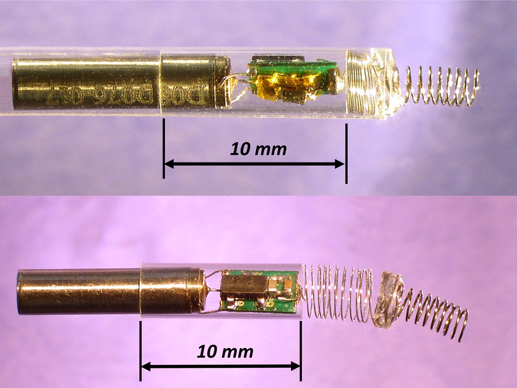
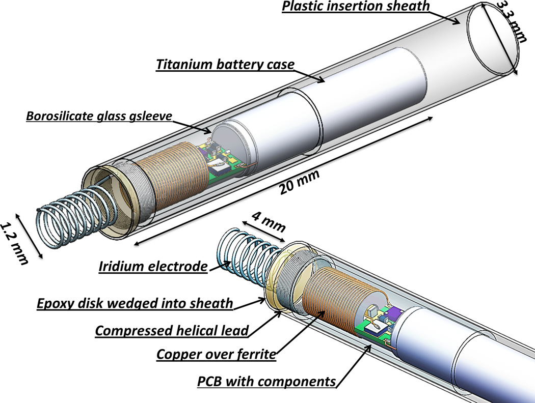
The fetal micropacemaker is designed for implantation through the largest commonly used intra-uterine cannula, which has an internal diameter of 3.3mm. The pacing system consists of a cylindrical micropacemaker containing the electronic circuitry and a lithium power cell as well as a screw electrode plus its flexible lead. The version illustrated in Figure 1 (Figure 1 goes here) contains working electronics for pulse generation powered by a primary cell. The design illustrated in Figure 2 incorporates an additional inductive coil and circuitry to allow recharging of a secondary cell from outside the mother’s abdomen via a radio-frequency magnetic field.
Figure 1.
A) Fetal micropacemaker within plastic insertion sheath; B) Pacemaker as deployed. Features left to right: battery case of lithium cell, which functions as return electrode, glass sleeve for epoxy encapsulation, printed circuit board with discrete surface-mount circuitry, flexible lead (0.075mm Pt-20Ir with Parylene-C insulation), epoxy disk over welded joint, corkscrew electrode (0.150mm Ir with Parylene-C insulation).
Figure 2.
Solid model of rechargeable micropacemaker incorporating circuitry illustrated in Figure 4.
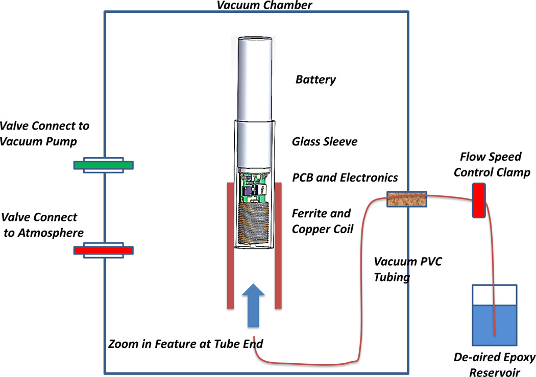
The electronics for both the primary cell and rechargeable designs are protected from body fluids by a thin-wall glass sleeve that is filled with a low permeability epoxy. Polymeric encapsulation is not truly hermetic like the titanium cases commonly used in pacemakers today, but it was a mainstay of cardiac pacemakers until the 1980s, when battery life was typically limited to 18–24 months. Such lifetimes are possible provided the diffusion path for water through the epoxy is long and the epoxy completely surrounds and adheres to the circuitry without leaving voids in which water can condense.14 In the design illustrated in Figures 1 and 2, (Figure 2 goes here) the glass sleeve provides a thin-wall form for the epoxy and a barrier to diffusion from the lateral surfaces, so that the diffusion paths to the electronics are long and narrow. The vacuum injection process for removing air bubbles and infiltrating the epoxy is illustrated in Figure 3. (Figure 3 goes here) After curing, the excess epoxy in the tube is removed by cutting just in front of the glass sleeve and through a platinum rod that projects out through the ferrite from the stimulus control capacitor (component C in Figure 4). (Figure 4 goes here) The subassembly consisting of the flexible lead (80% platinum – 20% iridium) and cork-screw electrode (pure iridium) is fabricated separately and insulated with vapor-deposited Parylene-C except for the exposed portion of the iridium electrode, which is masked during deposition by embedding it in clay. Parylene has been used to insulate chronically implanted electrodes because of it very high tensile strength, flexibility and stability in vivo.13 The proximal end of the flexible lead is resistance welded to the exposed cross-section of the platinum rod and reinforced with an overcoat of the epoxy.
Figure 3.
Epoxy injection molding system. The vacuum pulls air from the electronics and tubing through the slip fit between the titanium battery case and the borosilicate glass sleeve. When the flow control clamp is opened, epoxy flows slowly around the ferrite and copper coil and covers the printed circuit board (PCB) and electronic components and battery terminals. Flow is stopped before the epoxy flows out past the glass sleeve by releasing the vacuum. The epoxy is cured in place initially at room temperature and then post-cured in an oven.
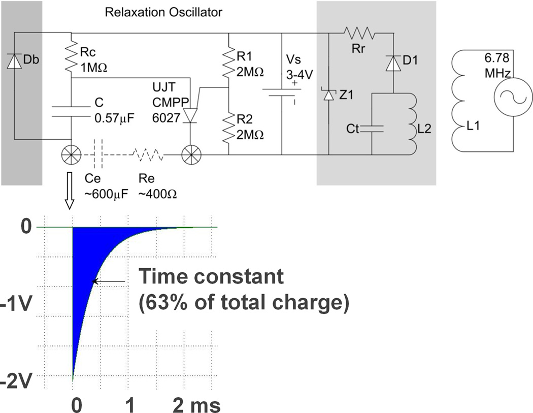
Figure 4.
Schematic diagram of relaxation oscillator (center top) with typical output pulse (insert below), with optional bypass diode Db for recharging through electrodes (dark grey box on left) and optional recharging circuitry (light grey box at right) for transcutaneous inductive recharging from external coil L1. See text for description of individual components. Insert below shows typical exponential cathodal pulse from corkscrew Ir electrode (open arrow) with typical values for Ce after activation and Re in myocardium.
The implantation and deployment scheme utilizes a thin-wall plastic sheath that contains the pacemaker assembly during sterilization and surgical handling. The epoxy reinforcing disk between the corkscrew electrode and the helical flexible lead is wedged into the end of the plastic sheath, leaving only the electrode exposed. Under ultrasound and fetoscopic guidance, the trocar and cannula are advanced from the maternal abdomen, through the uterine wall and fetal chest wall, until it abuts the fetal heart. The trocar is then removed and the plastic sheath assembly is inserted in its place. The fetal surgeon affixes the electrode to the myocardium by pushing and rotating the sheath so as to embed the protruding corkscrew electrode into the myocardium. The pacemaker continuously generates stimulus pulses, which pass into the myocardium from the electrode and return to the reference electrode (exposed back end of the lithium cell casing) via a fenestration in the plastic sheath. Adequate ventricular muscle capture can be assessed by ultrasonic imaging before the pacemaker is released from the sheath. Release is accomplished by a push rod (not illustrated) that advances the pacemaker assembly forward and therefore releases the epoxy disk out of the end of the plastic sheath as the sheath is withdrawn,12 leaving the pacemaker and unfurled helical lead lying in the chest of the fetus at a slight distance from the epicardial electrode.
Electronic Circuitry
The main challenge was to obtain the longest possible period of effective pacing within the limits of a tiny, off-the-shelf lithium cell (Quallion QL0003I, Sylmar, CA) and conventional surface-mount components. We achieved this by using a relaxation oscillator, an old design for pacemakers4 that requires a single active component and delivers virtually all of its consumed power as stimulation pulses (schematic diagram and output waveform illustrated in Figure 4). Output capacitor C is charged through resistor RC until its voltage reaches the threshold of the programmable unijunction transistor (UJT) as defined by voltage divider R1 and R2. The UJT then switches to a low impedance state that allows all of the charge accumulated on C to discharge through the electrode (an equivalent circuit is a capacitor in series with a resistor). The UJT then switches back into a high impedance state and begins another charge/discharge cycle whose rate is defined by time-constant = RC*C. The component values in the schematic reflect the most likely design based on the animal experiments described below.
Two approaches to charging the lithium cell are illustrated in grey boxes in the schematic diagram in Figure 4. Adding a diode Db that bypasses the output capacitor permits the rechargeable lithium cell to be maintained at full charge before implantation by connecting the output electrodes to an external recharging circuit. This recharging circuit can be powered by a relatively large primary cell that can be incorporated into the sterile packaging. Alternatively, it would be far more desirable to recharge the lithium cell repeatedly, including after implantation. This can be accomplished by incorporating the inductive coil L2 and tuning capacitor Ct illustrated in the schematic, which functions as a very weakly coupled transformer in conjunction with an external recharging coil L1 (see Figure 4). Because the coupling coefficient can vary widely depending on the orientation of the fetus, additional components need to be incorporated to avoid damage to the lithium cell from excessive voltage (zener diode Z1) or recharging current (limiting resistor Rr).
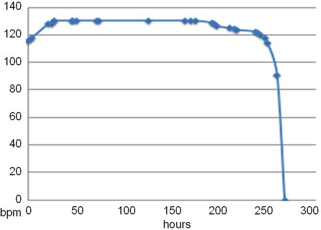
The rate at which the pacemaker battery will discharge is reasonably predictable (see below), but the effectiveness of the recharging process is variable due to the frequent changes in the orientation of the fetus in the womb. The battery voltage varies from approximately 3.0 to 4.0V depending on the state of charge, which causes a small but readily detectable change in the output pulse rate (Figure 5). (Figure 5 goes here) The brief but relatively intense stimulus pulses in the fetus generate widespread stimulus artifact signals that are easily recorded via skin electrodes on the mother’s abdomen. We have modeled a proposed recharging scheme based on a 40cm diameter transmitting coil operating at safe power levels in the 6.78MHz ISM band. Recharging the Quallion cell will take less than 2 hours at its maximal recommended rate of 1.5mA/h, provided the coil in the implanted pacemaker is less than 18.7cm from the plane of the transmitting coil on the mother’s abdomen and it is oriented approximately parallel to its flux lines. Due to the ability to predict the state of charge from the pacing rate, monitoring the maternal stimulus artifact rate throughout the recharging process will verify effective recharging.
Figure 5.
Stimulus rate (beats per minute) vs. hours of continuous pacing output for a high output design (6.38µC @ 2.9Vcompliance, 130bpm at full charge). The initial rate increase is a conditioning effect in the UJT when its threshold is set near Vs; it does not recur when recharged during continuous output.
Electrode Properties
Stimulus efficacy depends primarily on charge density of the pulse in the tissue immediately surrounding the active myocardial electrode. This is given by the integral of the stimulus current waveform over time divided by the cross-sectional area of the tissue. Stimulus efficacy depends secondarily on the rate at which that charge is delivered (peak current). It is desirable to deliver the charge as rapidly as possible, but this is limited by the available compliance voltage and the complex impedance represented by the metal-electrolyte interfaces of the electrodes and the intervening myocardial tissue: Istim = Vcompliance / (Zelectrode + Rtissue). With smaller electrodes, the density of the charge they emit increases while the impedance also increases. In the experiments described below, we tested two diameters of corkscrew electrode (1.3 and 2.2mm) wound from 0.15mm diameter iridium wire and sharpened at the tip using an abrasive wheel. The effect of the number of coils that were electrically exposed was also tested. This was controlled by masking the bare iridium wire during deposition of Parylene-C insulation.13
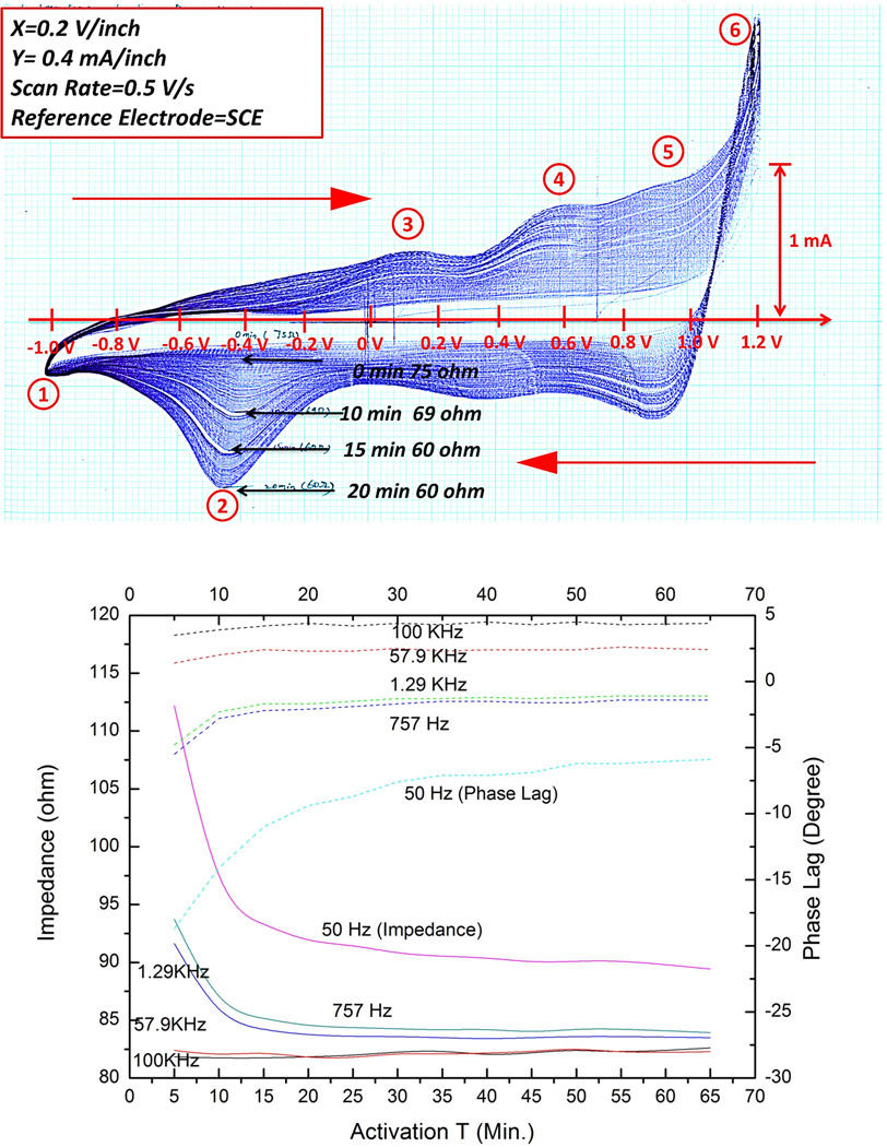
At low voltages below the limits where unsafe redox reactions can occur, the impedance can be modeled approximately as a resistance in series with a frequency-dependent capacitance (Re and Ce in Figure 4). Ce depends on the electrochemical properties of the metal electrode in the body fluids. We have chosen pure iridium for the electrode, both for its high mechanical strength (Young’s modulus = 528GPa) and for its ability to be “activated” by growing a conductive, porous oxide on its surface.19 This activation was accomplished by cyclic voltammetry, in which a potentiostatically controlled voltage ramp (0.5V/s) was applied to the electrode in phosphate-buffered physiological saline while monitoring the resulting current flow. As the oxide layer develops, its capacity to store and release charge increases greatly, as shown by the increasing area enclosed in successive cycles of the voltammogram in Figure 6A. This is reflected in impedance spectroscopy results in normal saline (Figure 6B), which shows substantial reductions in the impedance over time, particularly at lower frequencies. On the basis of these results, we adopted 20 minutes as the standard activation time for the electrodes tested in vivo. (Figure 6 goes here)
Figure 6.
Top: typical cyclic voltammetry curves (current on abscissa vs. applied voltage with respect to saturated calomel electrode in phosphate buffered physiological saline) for ±0.5V/s ramp between cathodal (1) and anodal (6) electrolysis points showing progressively larger enclosed charge; Bottom: impedance (solid lines, left ordinate) and phase (dotted lines, right ordinate) for various sinusoidal frequencies as a function of activation time (abscissa, minutes) for 1.3mm diameter Ir corkscrew electrode with 4 coils (2mm) exposed length in saline.
5. Results
Animal work was approved by and performed in accordance with guidelines of the University of Southern California's Animal Care and Use Committee (IACUC, protocol 11686), which adheres to the Guide in the Care and Use of Laboratory Animals established by the U.S. National Academy of Sciences.
In Vivo Percutaneous Implantation
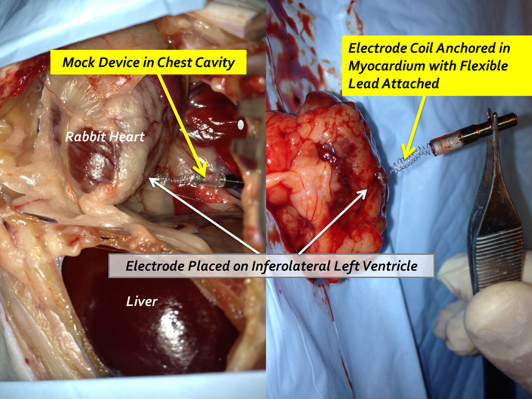
The tools and techniques for percutaneous device implantation were tested using an in vivo rabbit model. A non-functional device with identical dimensions and mechanical features of our fetal micropacemaker was implanted into an adult rabbit under general anesthesia, using a conventional cannula (3.8mm o.d. × 3.3mm i.d.) and the insertion sheath illustrated in Figure 1. The device was implanted into the actively beating rabbit myocardium from a subxyphoid approach, using transcutaneous ultrasound guidance and without the need for surgical incisions. A small amount of axial force on the insertion tool stabilized the motion of the ventrical at the tip of the corkscrew electrode as axial rotation implanted it into the myocardium in a few seconds. The animal was subsequently euthanized and explored surgically. We were able to confirm appropriate placement of the electrode in the myocardium with a favorable and safe position of the pacemaker and lead in the rabbit thorax (Figure 7). This demonstrates the feasibility of the strategy and instrumentation. Further mechanical implantation tests will be performed on a fetal sheep model, a more appropriate model of our clinical goals. (Figure 7 goes here)
Figure 7.
Percutaneous implantation site at post mortem exploration
In Vivo Pacing Threshold
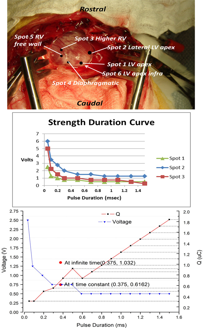
A set of activated iridium electrodes with varying coil diameters and exposure lengths were prepared and affixed to the end of a handle similar to the proposed insertion sheath. They were tested in three anesthetized adult rabbits weighing approximately 3kgs whose beating hearts were exposed via thoracotomy and then sacrificed with a barbiturate overdose. The electrodes were screwed into the myocardium at various locations (see Figure 8A) while monitoring the surface ECG. Pacing threshold was defined as the minimal value that produced ventricular myocardial capture (demonstrated by the presence of premature ventricular contractions on the ECG). Electrode impedance was measured in situ using a 1kHz, 10µA sinewave. Stimulation pulses were generated by a conventional clinical analyzer for pacemaker leads (Merlin Interrogator from St. Jude Medical, Sylmar, CA) that allowed independent control of square wave voltage and duration to determine threshold for capture. The stimulus charge was estimated from the measured electrode impedance (charge = duration × voltage/impedance). We also used a custom-built instrument that contained the UJT and associated circuitry for our fetal micropacemaker but with the ability to systematically vary C, Rc and Vs to determine thresholds for its exponential output pulse. (Figure 8 goes here)
Figure 8.
Top: insertion locations for data in Table 1; Middle: threshold strength-duration curves for square-wave stimuli; Bottom: Comparison of threshold charge (red lines; right ordinate) vs. pulse duration for square waves (black dots) and exponential pulses from relaxation oscillator (vertical red bar at time constant = 0.375ms) for pacing at Spot #1.
The strength-duration curves for three insertions of the 1.2mm diameter corkscrew electrode using a conventional square-pulse generator (Merlin Interrogator) are plotted in Figure 8B. The relaxation oscillator produces an exponentially declining stimulus (insert in Figure 4) that does not provide explicit control of current or duration, which will change depending on the actual impedance of the electrode. It does, however, provide precise control of the pacing charge (and hence power consumption) by varying capacitor C. Importantly, the charge required to pace was comparable to that of the square wave; see bracketed red line in Figure 8C for one placement of a 1.2mm coil electrode. The chronaxie for a conventional square-wave stimulus is approximately 0.5ms and its threshold charge lies between the total charge of the exponential pulse at infinity and the charge delivered at one time constant (τ=0.375ms). Note that only relatively coarse steps (factors of 2) were used for C, corresponding to the limited range of medical grade capacitors available in the 0402 surface mount package required for the implant.
Table 1 provides a complete set of data for the set of electrodes and placements illustrated in Figure 8A; similar but less complete data were obtained from the other two animals (4 placements in each animal, threshold charge 0.53 – 2.4µC). The electrode impedances and thresholds were somewhat variable but all within a useful range except for placement in Spot #3. The electrode did not penetrate the myocardium well at this location and the right ventricular wall at this location appeared to twist as the electrode was inserted due to the thinner myocardium. After electrode removal, the location appeared erythematous, unlike other insertions. The main factors affecting capture thresholds appeared to be the sharpness of the beveled tip of a given electrode and the number of different times it was inserted. In general the smaller diameter coils (1.2mm used exclusively in this animal) were more stable mechanically and easier to physically insert by applying gentle pressure and rotating the handle axially, mimicking the anticipated insertion technique when operating through the uterine cannula. Importantly, due to the flexibility of the electrode, there was no difficulty inserting the smaller corkscrew electrode even when oriented at a 45–60° oblique angle to the myocardial surface, as may well occur when the device is implanted in a human fetus in utero. Impedances and thresholds with the larger coils (2.3mm diameter) with similar lengths of exposed electrode were similar to those of the small coils but they were physically more difficult to implant, particularly for oblique insertions. (Table 1 goes here)
Table 1.
Electrode and pacing data from placements illustrated in Figure 8A.
| Electrode | #1 | #1 | #2 | #2 | #3 | #3 |
|---|---|---|---|---|---|---|
| Electrode coil diameter | 1.3 mm | 1.3 mm | 1.3 mm | 1.3 mm | 1.3 mm | 1.3 mm |
| Exposed | 3 turns | 3 turns | 3 turns | 3 turns | 4.5 turns | 4.5 turns |
| Spot | Spot #1 | Spot #2 | Spot #3 | Spot #4 | Spot #5 | Spot #6 |
| Location | LV apex | Lateral LV apex | High RV | Diaphragmatic | RV free wall | LV apex (infra) |
| Average impedance Ω | 408 | 415 | 362 | 428 | 313 | 312 |
| Square-wave threshold (1.3 ms dur.) |
0.5V | 0.75V | 2.75V | 1.25V | 0.5V | 0.5V |
| Square-wave threshold (0.5 ms dur.) |
0.75V | 1V | 3.75V | 1.5V | 0.75V | 1V |
| Exponential threshold (µC total) |
1.03 | 1.37 | >2.4 | 2.40 | 1.03 | 0.79 |
Power Optimization
Maximizing battery life depends on minimizing the power consumed by the stimulus pulses themselves and by the biasing resistors for the UJT (voltage divider R1–R2 in the schematic in Figure 4). Because the output of the pacemaker is determined by the fixed component values, the stimulus charge must include a reasonable safety margin over the measured capture thresholds to assure reliable pacing. The charge is the product of the capacitor value and the voltage range between peak charging (the threshold voltage for discharge through the UJT and complete discharge (approximately zero volts). When the UJT threshold is set near the maximal voltage to which the capacitor can be charged (i.e. the supply voltage Vs from the lithium cell), the UJT will not trigger reliably unless the values of R1 and R2 are set fairly low (<200K), resulting in substantial continuous current flow through the voltage divider. When Vthreshold = 0.8Vs, R1+R2 = 300K, resulting in 10µA, comparable to the continuous current needed to recharge output capacitor C. This problem can be minimized by reducing the threshold voltage to 0.5Vs, in which case R1 = R2 = 2MΩ and biasing current is <1µA. In order to maintain stimulus charge with a smaller voltage excursion, C must be increased accordingly. This has the effect of increasing the time constant of the stimulation pulse (product of C and tissue resistance Re), but the in vivo pacing data (above) indicate that these pulses are still shorter than the chronaxie for the heart muscle, so should produce effective and efficient pacing.
For the component values indicated in the schematic in Figure 4, the output pulse rate is 130 beats per minute with a charge of 0.73µC over a time constant of 0.375ms. The charging current is 1.58µA and the biasing current is 0.9µA; leakage current through the UJT is negligible. The 3mAh battery should last 50d on a single charge. These values, however, represent the best case conditions observed in the in vivo experiments (e.g. Figure 8C). A safety margin of at least a factor of 2:1 for the stimulus charge compared to the capture threshold would be prudent (see Table 1) and more may be indicated as a result of experiments in fetal sheep that remain to be performed.
6. Discussion
While the results to date have been encouraging, a number of steps remain before this device is ready for use in human fetuses.
Implanting and Pacing a Fetal Heart
The adult rabbits used in the experiments reported here have hearts similar in size to a 28-week human fetus but the chest wall anatomy and the inflated chest are significant differences of this model from that of human fetal implantation. The next set of animal implantations will be in a fetal sheep model, which not only provides a more physiologically appropriate model, but also allows chronic instrumentation (including femoral venous and arterial lines and fetal sheep skin electrodes for fetal ECG monitoring) without inducing premature labor.2, 23 A functional micropacemaker can be implanted percutaneously and left in place for the remainder of the pregnancy so that its efficacy, orientation and tissue encapsulation can be assessed. The pulse parameters required to pace the normal adult rabbit heart (Figure 8 & Table 1) or a normal fetal sheep heart may differ from those required in a hydropic human fetus, but data from a study by Assad et al. suggests that the differences may not be large. In that study, a strength duration curve was created using a different electrode design (T-bar shape without screw) in a 25-week hydropic human fetus at the time of implant and on the first postoperative day (POD).1 The patient died by 36 hours after implantation of the lead (which was connected to a pacemaker in the maternal abdominal wall) and the electrode design was different from our screw mechanism, but data from their strength-duration curve suggest a pacing threshold and chronaxie similar to our adult rabbit studies.
While our current electronic configuration results in a pacing rate of 130bpm, we anticipate that a rate of 100bpm would be used for human fetal application. This value is based on clinical experience with newborn pacing, and we therefore do not anticipate any negative cardiovascular effects from this increase in rate from the fetal heart block baseline rate (expected to be 40–60bpm). After the electrode screw is implanted in either a fetal sheep model or a human fetus, proper placement in the myocardium will be confirmed by determination of adequate pacing prior to release of the pacemaker from the insertion sheath. This will allow for the possibility of multiple screw insertion attempts prior to ultimate device placement, and will be particularly important when the fetal orientation results in more technically challenging implantations.
Extending Functional Life
The currently available rechargeable lithium cell is expected to support pacing for 15–20 days on a single charge. For fetuses that develop hydrops fetalis relatively late in gestation, continuous pacing for 2–3 weeks may be sufficient to resolve the hydrops and permit cesarean delivery with a good chance of survival. For other cases, however, we expect pacing will be required for a longer period. Primary lithium cell chemistry generally provides about three times the charge density of rechargeable chemistry, albeit at a somewhat lower voltage. A fetal pacemaker with the same dimensions could be constructed from a custom primary cell. If it were still near full charge at the time of implant, the 6–9 week device longevity would likely be sufficient for most, if not all, fetuses with heart block. Alternatively, the rechargeable lithium cell could be repeatedly recharged using the inductive coupling system described above. The external RF transmitter / coil could be used in a clinic or in-patient environment where it would be powered from a 110VAC receptacle. The recharging range would depend on the coil diameter and field strength that can be achieved without excessive heating of the coil or nearby skin. The magnetic flux density required to reach a sufficient voltage in the implant coil to recharge the battery depends on the distance between the two weakly coupled coils and their relative orientation.10 These factors can be observed using ultrasound but not controlled given the mobility of the fetus in the uterus. We anticipate that recharging will be performed under medical supervision and with monitoring of the actual battery charge as predicted by the pacing rate measured from the electrical artifact recordable on the mother’s abdomen (see Figure 5).
It may be desirable to use percutaneously implanted cardiac pacemakers in young children and even adults for which surgical implantation and intravenous passage of the electrical lead is undesirable. In most such applications, a functional life of years would be required. Substantial increases in the size of the pacemaker and its battery would likely be possible, which could substantially increase the recharging interval. It would then be feasible to use conventional hermetic packaging and to add bidirectional telemetry and digital control functions such as stimulus programmability. The fixed rate of the simple relaxation oscillator employed in the prototype presented here is not ideal but should be adequate for the last trimester of pregnancy. Perhaps the biggest challenge would be a flexible lead that could accommodate the small but continuous movement between the electrode in the myocardium and the pacemaker package in the chest.
Device Longevity and Biocompatibility
The fetal pacemaker will likely become ineffective shortly after delivery. The rapid expansion of the lungs and chest will certainly put stress on the flexible lead and the anchoring of the electrode in the myocardium. The open spiral of the flexible lead is not designed to accommodate large stresses or continuous flexing from respiratory and cardiac motion and the lithium cell will soon run down. Thus, we assume that a small, conventional demand pacemaker will be surgically implanted soon after birth.
The question arises as to whether and when a non-functional fetal pacemaker needs to be removed from the infant. The materials that form the outside surfaces of the fetal pacemaker include titanium battery case, iridium electrode, Parylene-insulated lead, borosilicate glass sleeve, and medical-grade epoxy. All have a long history of use in chronically implanted medical devices, so we anticipate successful biocompatibility testing, which would be required on the completed device. Accelerated life-testing of the non-hermetic packaging at elevated temperature and pressure in saline will be required to demonstrate that the electronic circuit continues to function for the required period of at least 3 months. These tests can be extended to demonstrate whether there are degradation modes of the inactive device that could pose a danger, such as swelling and disruption of the epoxy package.
Clinical Translation
It is estimated that approximately 500 pregnancies in the United States are affected by fetal heart block annually and may be candidates for this device.16 In view of this relatively small market, we have applied for and been awarded a Humanitarian Use Device [HUD; 21 CFR 814(h)] designation by the US Food & Drug Administration (FDA). Under this designation, first-in-human studies after the completion of the ongoing development and testing can be pursued according to a Humanitarian Device Exemption (HDE), rather than standard Investigational Device Exemption (IDE) processes. The HDE pathway allows a product to be marketed with a demonstration of safety rather than efficacy and with reduced Good Manufacturing Practices (GMP) requirements compared to a Premarket Approved (PMA) product.
If our percutaneously implantable micropacemaker proves successful, it will provide an extremely effective treatment option for a population of fetuses that would either die in utero or require premature delivery with all of its comorbid consequences. The fetal market is too small to attract major investment by industry, so we have identified a way to address the key anatomical, physiological and surgical issues while using off-the-shelf electronic components. Commercial organizations (including Medtronic, Inc., Minneapolis, MN), have recognized the need for smaller pacing devices and are developing “leadless” pacemakers for transvenous implantation. These models, however, are designed for endovascular use and do not have the active fixation mechanisms necessary for fetal use, nor the flexible lead systems required for transthoracic implantation. Once available, our class of injectable epicardial devices could be extended to newborns, infants, and even adults with limited venous access and/or contraindications to open surgery.17 As battery technology inevitably improves, this technology could replace standard single-chamber pacemaker techniques with implantation of the entire pacing system into the patient’s thorax via a minimally invasive technique. In this time of expanding micro- and nano-technology, we see our percutaneously implantable micropacemaker as the natural evolution of pacemakers and anticipate a much wider application of this and related microdevices.
Acknowledgments
This research was funded by the Southern California Clinical and Translational Science Institute and by the Robert E. and May R. Wright Foundation. The authors thank consultant Glen Griffith for feasibility analysis of the inductive recharging scheme, and thank Dr. Erlinda Kirkman for providing veterinarian assistance for the animal models used in this report.
References
- 1.Assad RS, Zielinsky P, Kalil R, Lima G, Aramayo A, Santos A, Costa R, Marcial MB, Oliveira SA. New lead for in utero pacing for fetal congenital heart block. J. Thorac. Cardiovasc. Surg. 2003;126(1):300–302. doi: 10.1016/s0022-5223(03)00220-4. [DOI] [PubMed] [Google Scholar]
- 2.Bessette NW, Rurak DW. Chronic fetal and maternal instrumentation in pregnant sheep: Effect on gestation length and birthweight. Reprod. Fertil. Dev. 2010;22(2):459–467. doi: 10.1071/RD09156. [DOI] [PubMed] [Google Scholar]
- 3.Carpenter RJ, Jr, Strasburger JF, Garson A, Jr, Smith RT, Deter RL, Tristan Engelhardt H., Jr Fetal ventricular pacing for hydrops secondary to complete atrioventricular block. J. Am. Coll. Cardiol. 1986;8(6):1434–1436. doi: 10.1016/s0735-1097(86)80319-9. [DOI] [PubMed] [Google Scholar]
- 4.Dresbach JB inventor. Noncompetitive pacemaker with programmable unijunction transistors. 3898995. United States patent U.S. 1975 Aug 12;
- 5.Eliasson H, Sonesson S-E, Sharland G, Granath F, Simpson JM, Carvalho JS, Jicinska H, Tomek V, Dangel J, Zielinsky P, Respondek-Liberska M, Freund MW, Mellander M, Bartrons J, Gardiner HM. Isolated atrioventricular block in the fetus / clinical perspective. Circulation. 2011;124(18):1919–1926. doi: 10.1161/CIRCULATIONAHA.111.041970. [DOI] [PubMed] [Google Scholar]
- 6.Friedman DM, Kim MY, Copel JA, Davis C, Phoon CKL, Glickstein JS, Buyon JP. Utility of cardiac monitoring in fetuses at risk for congenital heart block. Circulation. 2008;117(4):485–493. doi: 10.1161/CIRCULATIONAHA.107.707661. [DOI] [PubMed] [Google Scholar]
- 7.Friedman DM, Llanos C, Izmirly PM, Brock B, Byron J, Copel J, Cummiskey K, Dooley MA, Foley J, Graves C, Hendershott C, Kates R, Komissarova EV, Miller M, Paré E, Phoon CKL, Prosen T, Reisner D, Ruderman E, Samuels P, Yu JK, Kim MY, Buyon JP. Evaluation of fetuses in a study of intravenous immunoglobulin as preventive therapy for congenital heart block: Results of a multicenter, prospective, open-label clinical trial. Arthritis Rheum. 2010;62(4):1138–1146. doi: 10.1002/art.27308. [DOI] [PMC free article] [PubMed] [Google Scholar]
- 8.Groves AM, Allan LD, Rosenthal E. Outcome of isolated congenital complete heart block diagnosed in utero. Heart. 1996;75(2):190–194. doi: 10.1136/hrt.75.2.190. [DOI] [PMC free article] [PubMed] [Google Scholar]
- 9.Groves AM, Allan LD, Rosenthal E. Therapeutic trial of sympathomimetics in three cases of complete heart block in the fetus. Circulation. 1995;92(12):3394–3396. doi: 10.1161/01.cir.92.12.3394. [DOI] [PubMed] [Google Scholar]
- 10.Heetderks WJ. RF powering of millimeter- and submillimeter-sized neural prosthetic implants. IEEE Trans.Biomed.Eng. 1988;35(5):323–327. doi: 10.1109/10.1388. [DOI] [PubMed] [Google Scholar]
- 11.Ho SY, Esscher E, Anderson RH, Michaëlsson M. Anatomy of congenital complete heart block and relation to maternal anti-ro antibodies. Am. J. Cardiol. 1986;58(3):291–294. doi: 10.1016/0002-9149(86)90064-0. [DOI] [PubMed] [Google Scholar]
- 12.Kaplan H, Loeb G. Design and fabrication of an injection tool for neuromuscular microstimulators. Ann. Biomed. Eng. 2009;37(9):1858–1870. doi: 10.1007/s10439-009-9739-5. [DOI] [PubMed] [Google Scholar]
- 13.Loeb GE, Bak MJ, Salcman M, Schmidt EM. Parylene as a chronically stable, reproducible microelectrode insulator. IEEE Trans.Biomed.Eng. 1977;24(2):121–128. doi: 10.1109/TBME.1977.326115. [DOI] [PubMed] [Google Scholar]
- 14.Loeb GE, Mchardy J, Kelliher EM. Neural prosthesis. In: Williams DF, editor. Biocompatibility in clinical practice. vol. I. Boca Raton: CRC Press, Inc.; 1982. pp. 123–149. [Google Scholar]
- 15.Loeb GE, Richmond FJR. Making design controls useful for r&d. Med. Device Diagn. Ind. 2003;25(4):63–68. [Google Scholar]
- 16.Lopes LM, Tavares GMP, Damiano AP, Lopes MAB, Aiello VD, Schultz R, Zugaib M. Perinatal outcome of fetal atrioventricular block. Circulation. 2008;118(12):1268–1275. doi: 10.1161/CIRCULATIONAHA.107.735118. [DOI] [PubMed] [Google Scholar]
- 17.Mcleod KA. Cardiac pacing in infants and children. Heart. 2010;96(18):1502–1508. doi: 10.1136/hrt.2009.173328. [DOI] [PubMed] [Google Scholar]
- 18.Pisoni CN, Brucato A, Ruffatti A, Espinosa G, Cervera R, Belmonte-Serrano M, Sánchez-Román J, García-Hernández FG, Tincani A, Bertero MT, Doria A, Hughes GRV, Khamashta MA. Failure of intravenous immunoglobulin to prevent congenital heart block: Findings of a multicenter, prospective, observational study. Arthritis Rheum. 2010;62(4):1147–1152. doi: 10.1002/art.27350. [DOI] [PubMed] [Google Scholar]
- 19.Robblee LS, Lefko JL, Brummer SB. Activated ir: An electrode suitable for reversible charge injection in saline solution. J. Electrochem. Soc. 1983;130(3):731–733. [Google Scholar]
- 20.Robinson BV, Ettedgui J, Eacute A, Sherman FS. Use of terbutaline in the treatment of complete heart block in the fetus. Cardiol. Young. 2001;11(06):683–686. doi: 10.1017/s1047951101001123. [DOI] [PubMed] [Google Scholar]
- 21.Schmidt KG, Ulmer HE, Silverman NH, Kleinman CS, Copel JA. Perinatal outcome of fetal complete atrioventricular block: A multicenter experience. J. Am. Coll. Cardiol. 1991;17(6):1360–1366. doi: 10.1016/s0735-1097(10)80148-2. [DOI] [PubMed] [Google Scholar]
- 22.Walkinshaw SA, Welch CR, Mccormack J, Walsh K. In utero pacing for fetal congenital heart block. Fetal Diagn. Ther. 1994;9(3):183–185. doi: 10.1159/000263929. [DOI] [PubMed] [Google Scholar]
- 23.Westgate JA, Gunn AJ, Bennet L, Gunning MI, De Haan HH, Gluckman PD. Do fetal electrocardiogram pr-rr changes reflect progressive asphyxia after repeated umbilical cord occlusion in fetal sheep? Pediatr. Res. 1998;44(3):297–303. doi: 10.1203/00006450-199809000-00006. [DOI] [PubMed] [Google Scholar]


