Abstract
Radiofrequency (RF)-spoiled gradient-echo imaging provides a signal intensity close to pure T1 contrast by using spoiler gradients and RF phase cycling to eliminate net transverse magnetization. Generally, spins require many RF excitations to reach a steady-state magnetization level; therefore, when unsaturated flowing spins enter the imaging slab, they can cause undesirable signal enhancement and generate image artifacts. These artifacts can be reduced by partially saturating an outer slab upstream to drive the longitudinal magnetization close to the steady state, while the partially-saturated spins generate no signal until they enter the imaging slab. In this work, magnetization evolution of flowing spins in RF-spoiled gradient-echo sequences with and without partial saturation was simulated using the Bloch equations. Next, the simulations were validated by phantom and in vivo experiments. For phantom experiments, a pulsatile flow phantom was used to test partial saturation for a range of flip angles and relaxation times. For in vivo experiments, the technique was used to image the carotid arteries, abdominal aorta, and femoral arteries of normal volunteers. All experiments demonstrated that partial saturation can provide consistent T1 contrast across the slab while reducing inflow artifacts.
Keywords: RF spoiling, T1 contrast, flow, steady state, flow artifacts
Introduction
Gradient-echo sequences are characterized by a train of radiofreqeuncy (RF) excitation pulses and gradient pulses. A steady-state magnetization can be achieved when each sequence repetition meets the following conditions: constant flip angle; constant, or linearly or quadratically increasing, RF phase; constant repetition time (TR); and constant dephasing by gradients [1]. The steady-state signal contrast is determined by flip angle, T1, T2, TR, and echo time (TE). When the TR is much longer than T2 (TR ≫ T2), the transverse magnetization decays to zero before the next excitation pulse. In this case, the steady-state signal does not depend on T2, and T1-weighted contrast is achieved. However, when the TR is comparable to or shorter than T2, the transverse magnetization can no longer be neglected. Sequential RF pulses partly refocus transverse magnetization, leading to spin echoes, stimulated echoes, and higher order echoes. Therefore, the resultant steady-state signal is a composite of free induction decay (FID) and echoes [2], and the steady-state signal depends on both T1 and T2.
Several strategies have been developed to spoil transverse magnetization and to provide pure T1 contrast for short TR sequences [3–7]. Among them, RF spoiling, which combines RF phase cycling with spoiler gradients [5, 7], has emerged as the most commonly used solution. RF spoiling increases the phases of sequential RF pulses quadratically, where the phase difference between two consecutive RF pulses is linearly incremented. This alters the contribution of each echo to the steady-state signal. With a certain phase difference increment, the steady-state signal is dominated by the FID because other echoes add destructively and cancel. Conventionally, a phase increment angle of 117° has been used to spoil transverse magnetization [7], but other angles such as 84° [8], 96.5° [9], 50° [10], and 150° [11] are also suggested to provide better convergence properties or more accurate T1 estimation.
RF-spoiled gradient-echo sequences are often used for 3D dynamic contrast-enhanced imaging, where repetitive rapid T1 imaging is necessary to measure passage of the contrast agent in tissue. Signal intensity can be directly used for estimating contrast concentration because contrast concentration is proportional to 1/T1 of tissue. For perfusion quantification, the arterial input function (AIF), which is a time history of contrast concentration in the artery of interest, should be known. However, fresh and unsaturated blood that enters the imaging slab can generate flow artifacts and cause errors in the AIF measurement. Two detrimental flow artifacts are inflow enhancement [12] and pulsatile ghost artifacts [13, 14]. Inflow enhancement occurs at entry slices, generating signal intensity higher than pure T1 contrast, and can lead to overestimation of contrast concentration. Pulsatile ghost artifacts arise from view-to-view signal fluctuations caused by entrance of different amounts of unsaturated magnetization over a cardiac cycle, hiding anatomical details.
Several calibration methods have been proposed to determine the accurate AIF from images affected by flow artifacts; however, they require extra flow velocity measurement [15,16]. Instead of inflow-corrected calibration, imaging blood with reduced flow artifacts can be a more direct approach to improve accuracy. One strategy is to drive the magnetization of flowing spins to the steady state before image acquisition. Applying a saturation pulse and then waiting for a prescribed recovery period [9] can quickly drive spins to the steady state for both stationary and flowing spins. However, because of a single recovery period, the steady state can only be achieved for a limited range of T1 values. Recently, applying partial saturation on a slab upstream from the imaging slab has been proposed as a method to drive flowing spins to the steady state before they enter the imaging slab, showing feasibility to improve the AIF measurement [17].
In this work, we thoroughly analyze and test partial saturation of flowing spins, demonstrating its ability to reduce flow artifacts and to provide T1 contrast for 3D RF-spoiled gradient-echo imaging. We simulate complicated magnetization evolution for stationary spins and flowing spins with and without partial saturation. We then validate the simulation by performing flow phantom experiments and in vivo experiments. For phantom experiments, we compare signal intensity variations across the slab for different T1 mixtures and imaging flip angles with no flow, flow without partial saturation, and flow with partial saturation. For in vivo experiments, we investigate reduction of flow artifacts for several different arteries in normal volunteers.
Materials and Methods
Pulse Sequence with Partial Saturation
Partial saturation of flowing spins can be achieved by placing a partial saturation slab upstream to the imaging slab as shown in Fig. 1a. In this work, the 3D imaging slab and the partial saturation slab were overlapped by one slice thickness. For each pulse sequence repetition, the partial saturation RF pulse preceded the imaging RF pulse (Fig. 1b). Both the partial saturation and imaging RF pulses used identical minimum-phase pulses with a 3.2 msec duration and a time-bandwidth product of 20, having identical flip angles and phase cycling.
Figure 1.
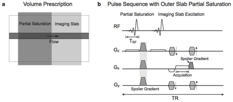
Partial saturation of flowing spins. a: A partial saturation slab is located upstream, exterior to the 3D imaging slab with one slice of overlap. b: For each pulse sequence, the partial saturation RF pulse is placed before an imaging RF pulse. Spoiler gradients are located at two different time points to provide RF spoiling as well as to avoid generating signal from the partial saturation slab during data acquisition.
When applying partial saturation to eliminate flow artifacts, there are several key considerations. First, the partial saturation slab should be thick enough for flowing spins to experience a sufficient number of excitations to reach a steady state. Thus, the partial saturation slab thickness should be determined with considering the flow velocity. Second, no signal should arise from the partial saturation slab during data acquisition. Therefore, spoiler gradients should be applied not only to provide RF spoiling but also to avoid signal generation from the partial saturation slab during data acquisition.
In particular, we placed spoiler gradients at two different times for each sequence repetition, at the end of the partial saturation RF pulse and at the end of the readout gradient. Immediately after the partial saturation RF pulse, spoiler gradients were applied along the x, y, and z axes simultaneously to maximize dephasing in the presence of a nonuniform slab phase profile and possible high spatial frequency components of the object along any axis. Following the readout gradient, a spoiler gradient was applied along the x axis to exploit the unbalanced part of the preceding readout gradient for spoiling. Spoiler gradients applied in the direction of flow generate additional phase accumulation for flowing spins [18], but as described in “Discussion” the overall spoiling is not usually adversely affected.
Phase Graphs
In this section, we provide phase graphs and signal evolution simulations for stationary spins with our pulse sequence to analyze signal generation and dephasing over time [19,20]. For simplification, the phase graphs are drawn assuming the spoiler gradients are applied only along one axis (x axis). The additional use of y and z spoiler gradients after the partial saturation RF pulse in the actual pulse sequence would not refocus the magnetization dephased by x spoiler gradients nor vary the net signal from each voxel. In addition, we assumed that each spoiler gradient is applied for the duration of TR/2 − TRF and generates a phase twist of −π to π radians within each voxel, and data acquisition is performed instantaneously at TR/2 + TRF (Fig. 2a). Denoting Fn as a dephased transverse magnetization state with n cycles of phase twist (i.e., 2πn) within a voxel, Fig. 2b and c presents phase graphs for the imaging slab and partial saturation slab, respectively.
Figure 2.
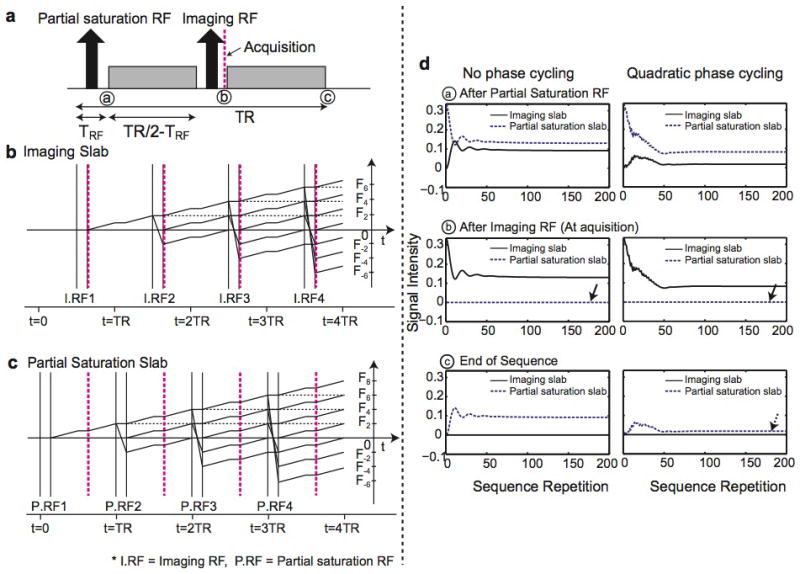
a: Simplified pulse sequence using RF pulses and spoiler gradients. Spoiler gradients are located at two different times. b–c: The phase evolution from a voxel for the imaging slab (b) and the partial saturation slab (c) is presented over the first four sequence repetitions. The acquisition points are denoted as dashed vertical lines. At those points, the imaging slab generates a signal consisting of free induction decay and refocused echoes, but the partial saturation slab does not generate any signal because magnetization consists only of dephased states with odd numbers of n (…, F−3, F−1, F1, F3, …). d: Simulated signal evolution from a voxel at three different places over the sequence is presented. The left and right columns show signal evolution both without and with RF phase cycling, respectively. The solid arrows indicate that no signal occurs from the partial saturation slab during data acquisition. Note that some nonzero steady-state signal occurs at the end of the sequence from the partial saturation slab even with RF spoiling (dashed arrow).
The phase graphs demonstrate that at the acquisition time, the magnetization in the imaging slab consists of magnetization states with even numbers of n (…, F−4, F−2, F0, F2, F4, …) where nonzero net signal is produced due to the F0 state; however, the magnetization in the partial saturation slab consists of magnetization states with odd numbers of n (…, F−3, F−1, F1, F3, …), resulting in no signal. These magnetization pathways do not depend on the RF phase, and RF phase cycling only alters the amplitude and the phase of each magnetization substate.
Figure 2d shows the signal evolution of each voxel from both the imaging slab and partial saturation slab, calculated using the Bloch equations over two hundred sequence repetitions. The signal evolution at three different time points along the sequence [(a) at the end of partial saturation RF pulse, (b) at the end of imaging RF pulse, and (c) at the end of the sequence) is presented. Tissue or scan parameters of T1/T2 = 1000/200 msec, flip angle = 20°, and TR/TE = 20/4 msec were used. The left and right columns present signal evolution without and with RF phase cycling (117° phase increment angle), respectively. At the end of the imaging RF pulse, no signal occurs from the partial saturation slab for both cases because the transverse magnetization only consists of dephased magnetization states. However, nonzero steady-state signal occurs at the end of the sequence from the partial saturation slab even with RF spoiling because of imperfect cancelation of echoes (dashed arrows). This indicates that RF-spoiling is not perfect in eliminating transverse magnetization. Therefore, complete dephasing of the partial saturation slab is only possible at the time between the spoiler gradients.
Magnetization Simulations
We first calculated the theoretical magnetization evolution due to the pulse sequence in Fig. 1b using the Bloch equations for stationary spins and for flowing spins with and without partial saturation RF pulses. Simulation ranges included an imaging slab with 9.6 cm thickness (32 slices), a partial saturation slab with 5–15 cm thickness when partial saturation is used, and extra regions with 4 cm thickness upstream and downstream to those slabs. For each voxel, 40 × 40 isochromats were located and simulated over the xz plane, excluding the y dimension. Phase-encode and readout gradients were not incorporated, and the x and z spoiler gradients immediately after the partial saturation RF pulse were applied whether the partial saturation RF pulse was turned on or not. Other parameters were T1/T2 = 1000/200 msec (close to those of blood at 1.5T), TR/TE = 20/4 msec, and flip angle = 20°.
For flowing spins, we compared the magnetization of steady and periodic flow, both with a mean velocity of 10 cm/s. For periodic flow, pulsatile flow was mimicked using a half cosine for systole and zero for diastole over each period. We assumed there is no spatial dependence on velocity profiles. Motion due to flow was incorporated by spatially shifting the magnetization vectors at the end of each TR based on the velocity, and filling empty spots with full magnetization. By incorporating the change of z location over time for each spin, the additional phase accumulation by the z spoiler gradient was taken into account. Flow effects during RF excitation [21, 22] were neglected with this discrete flow.
Phantom Experiments
We conducted phantom experiments to validate the simulations using a 1.5T GE HDx scanner and a standard GE birdcage head coil (GE Healthcare, Waukesha, WI). First, we verified complete dephasing of the partial saturation slab. A resolution phantom was used for verification, and an imaging slab and partial saturation slab (both 10 cm-thick) were prescribed and encoded together by extending the imaged field of view in the slab-direction to 30 cm. From acquired images, a signal profile along the z axis was measured.
Next, we performed experiments using an electric pump that generates pulsatile flow in a connected pliable tube with a 6 mm inner diameter. The long tube penetrated a bottle filled with agar and the immobilized part of the tube within the bottle was used for flow analysis. The mean flow velocity was set at 10 cm/s, and the temporal portion of systole to diastole for periodic flow was set at 1:1. Liquid relaxation properties were varied by doping pure water with Gadoteridol (Gd-DOPA). The first mixture had a Gd-DOPA concentration of 0.09 mmol/kg with measured T1/T2 of 1160/550 msec, and the second mixture had a concentration of 0.25 mmol/kg with measured T1/T2 of 520/360 msec.
For each of two Gd-DOPA mixtures, three different flip angles of 10°, 20°, and 30° were tested, and for each case, three different scans were conducted: (1) with no flow and no partial saturation; (2) with flow and no partial saturation; and (3) with both flow and partial saturation. Other acquisition parameters were TR/TE = 20/4 msec, 20 × 20 cm2 field of view, 192 × 192 in-plane matrix size, a 10.8 cm-thick imaging slab throughout 36 slices, and a 16 cm thick partial saturation slab. After scans, the signal variation across the slab was measured and compared from regions of interest (ROIs) located in the tube for each slice.
In Vivo Experiments
After acquiring informed consent, we scanned healthy volunteers to test partial saturation in the carotid arteries, abdominal aorta, and femoral arteries. Specifically, we performed five neck scans, one abdomen scan, and four leg scans using a four-channel phased-array neurovascular coil (MRI Devices Corp, Waukesha, WI), eight-channel phased-array cardiac coil (GE Healthcare, Waukesha, WI), and eight-channel phased-array knee coil (MRI Devices Corp, Waukesha, WI), respectively. Common parameters for all acquisitions were TR = 17–20 msec, TE = 4 msec, flip angle = 20°, and 36 slices with 0.3–0.4 cm slice thickness. For the neck and leg scans, in-plane matrix sizes of 256 × 256 and 256 × 192 were used, respectively, and for the abdomen scan, a 64 × 64 matrix size was used to yield a 40 s scan time to enable a single breathhold. We conducted imaging with and without a 16 cm-thick partial saturation slab and compared signal intensity change along the arteries using ROI analysis. For the carotid and femoral arteries, the intensity inhomogeneity from coil sensitivity variation was corrected incorporating reference body coil images [23]. However, this coil sensitivity variation was not compensated for the abdominal aorta because cardiac motion made it difficult to estimate accurate correction factors.
Results
Magnetization Simulations
The magnetization evolution for stationary spins, and for steady and pulsatile flow with and without a 10 cm partial saturation slab is shown in Fig. 3. Figure 3a, c, e, h, and j shows the magnitude of transverse magnetization of isochromats on each z location immediately after applying the imaging RF pulse for the first 200 sequence repetitions. From the simulated magnetization of 40 × 40 isochromats on each voxel (over the xz plane), magnetization along the z axis at a particular x location is displayed. The images on the right of those images show the magnitude of net transverse magnetization obtained by averaging isochromats in each voxel.
Figure 3.
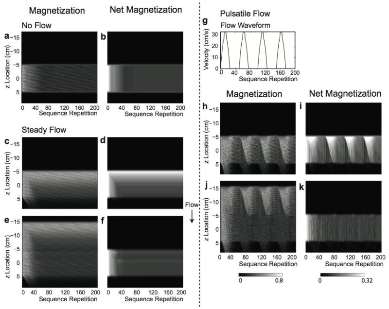
Magnetization simulation. Evolution of transverse magnetization of each isochromat along the z axis and net transverse magnetization from each voxel over 200 sequence repetitions (over 4 sec with TR = 20 msec) is shown for stationary spins (a, b), for steady flow without partial saturation (c, d) and with partial saturation (e, f), and for pulsatile flow without partial saturation (h, i) and with partial saturation (j, k). The flow is in the positive z direction, and the pulsatile flow waveform used is shown in (g). For stationary spins, each spin attains a periodic pseudo-steady state (a); however, the net magnetization of each voxel reaches a steady state (b). Inflow enhancement is greatly reduced by partial saturation for both steady and pulsatile flow (f, k). Slight signal fluctuation from sequence to sequence remains with pulsatile flow (k).
For stationary spins (Fig. 3a), individual spins do not attain a single steady state due to quadratic RF phase cycling; instead, the magnetization becomes periodic and reaches a “pseudo steady state” [24]. The net magnetization provides a uniform signal profile along the z axis (Fig. 3b).
For steady flow without partial saturation, unsaturated spins at entry slices generate high magnitude magnetization, leading to inflow enhancement at entry slices, and approach a steady-state level as they move into the imaging slab (Fig. 3c–d). By applying partial saturation, spins are partially saturated before entering the imaging slab so that inflow enhancement is almost eliminated (Fig. 3e–f). Within the partial saturation region, even though the transverse magnetization of each isochromat is not zero, the net magnetization is approximately zero, demonstrating complete dephasing of the partial saturation slab. Small transient effects occur at the entry regions of the imaging slab, caused by the RF magnetic field change at the intersection of the partial saturation slab and the imaging slab.
For pulsatile flow, a velocity waveform shown in Fig. 3g is used, assuming a heart rate of 60 beats per minute with a mean velocity of 10 cm/s. The number of unsaturated spins entering the imaging slab varies with the flow velocity, resulting in significant signal variation over time (Fig. 3h–i). However, when partial saturation is used, the inflow enhancement and signal variation over time are greatly reduced (Fig. 3j–k) even though some signal fluctuation from repetition to repetition remains (Fig. 3k).
In Fig. 4a, signal profiles from simulations in Fig. 3 are plotted together. For no flow and steady flow, the signal profiles from the last sequence repetition are used because the net signal from each voxel reaches a single value. However, for pulsatile flow, averaged profiles over the fourth cardiac cycle are plotted to show the mean signal level from signal fluctuation. The signal profiles show that inflow enhancement is greatly reduced by using partial saturation for both steady flow and pulsatile flow. With steady flow, slight signal fluctuation can be seen in the entry slices due to a change in the experienced RF field. With pulsatile flow, the oscillation effects and fluctuation are averaged out within a cardiac cycle, and a more uniform flow profile can be achieved, resulting in signal intensity close to that of stationary spins. In Fig. 4b, the signal profiles from pulsatile flow by varying the partial saturation slab thickness are compared with the profiles from no flow and pulsatile flow without partial saturation. By using a partial saturation thickness of at least 10 cm, inflow enhancement is almost completely eliminated for flow with the mean velocity of 10 cm/s.
Figure 4.
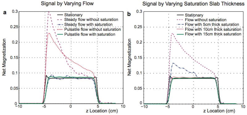
Simulated net signal profiles along the z direction. a: Signal profiles for no flow, steady and pulsatile flow without partial saturation, and steady and pulsatile flow with a partial saturation slab with 10-cm thickness. For pulsatile flow, signal fluctuation over time is averaged over one cardiac cycle. b: Signal profiles for no flow, pulsatile flow without partial saturation, and pulsatile flow with partial saturation slab thickness of 5, 10, and 15 cm. By partially-saturating a slab at least 10 cm thick, the profile from flowing spins becomes similar to that of stationary spins.
Phantom Experiments
Results from the resolution phantom experiment to examine residual signal in the partial saturation slab are presented in Fig. 5. Regions of the imaging slab and the partial saturation slab are denoted on the coronal localizer image in Fig. 5a. The coronal reformatted image from the large slab-direction field-of-view scan encoding both the imaging slab and partial saturation slab is also shown in Fig. 5b. The signal profile measured along the dotted line indicates that spins from the partial saturation slab generate no net signal.
Figure 5.
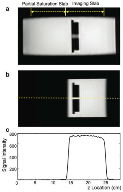
Phantom experiment to examine dephasing of the partial saturation slab. a: The location of the imaging slab and partial saturation slab with each 10-cm thick on a localizer image. b: Coronal reformatted image from the 30 cm-slab-direction field-of-view scan with applying partial saturation. c: A signal profile along the dashed line denoted in (b), demonstrating that the partial saturation slab is dephased completely, generating no net signal.
Results from flow phantom experiments using the pulsatile flow pump are illustrated in Figs. 6 and 7. Figure 6 shows maximum intensity projection of the tube after coronal reformat when Gd-DOPA doped water (T1/T2 = 520/360 msec) and a 30° flip angle were used. MIP images demonstrate that partial saturation greatly reduced inflow enhancement and pulsatile ghost artifacts.
Figure 6.
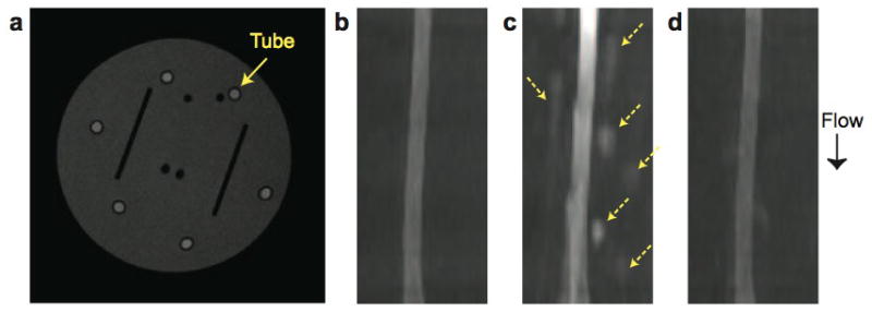
Flow phantom experiment. Here phase encoding in two axes is performed by acquiring all ky lines before moving to the next kz location. a: Axial phantom image with a tube for flow. b–d: Maximum intensity projection of the tube after coronal reformat for stationary water (b), flowing water without (c) and with (d) partial saturation. Inflow enhancement and ghost artifacts (dashed arrows) which occur with pulsatile flow are greatly reduced by using partial saturation.
Figure 7.
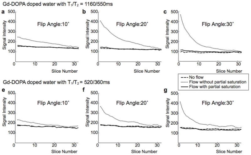
The signal intensity change along the tube was quantified using manually-placed ROIs. For Gd-DOPA doped water with T1/T2 = 1160/550 msec (a–c) and 520/360 msec (d–f), flip angles of 10°, 20°, and 30° were examined. In all six cases, partial saturation reduces inflow enhancement almost completely and generates uniform signal intensity across the slab with a signal level similar to when there is no flow.
Figure 7 compares signal intensity variations over the 32 slices (after discarding 4 slices at the 2 edges of the slab) along the tube for no flow, flow without partial saturation, and flow with partial saturation. Signal intensity was measured in an ROI consisting of 26 pixels, with an area of 0.16 cm2. From the two different Gd-DOPA mixtures and three different flip angles, the measured signal levels were different; however, for all six cases, partial saturation provided uniform signal intensity across the slab for the flowing spins, achieving a signal level similar to that of stationary spins.
In Vivo Experiments
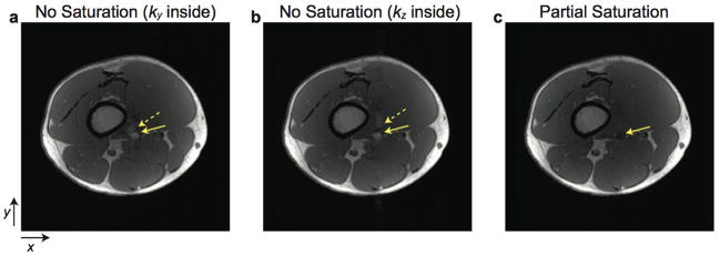
In vivo leg images from the second superior slice are shown in Fig. 8. When partial saturation was not used, inflow enhancement and pulsatile ghost artifacts were observed due to inflow in the femoral artery. Ghost artifacts were generated along the z direction when ky lines were acquired for the inside phase-encoding loop (a); and ghost artifacts were generated along the y direction when kz lines were acquired as the inside phase-encoding loop (b). These signal variations and artifacts were greatly eliminated by using partial saturation (c).
Figure 8.
In vivo leg images. The femoral artery of the leg is depicted by solid arrows. a–b: Without partial saturation. (a) is acquired with ky as the inner acquisition loop, while (b) is acquired with kz as the inner loop. Pulsatile ghost artifacts (dashed arrows) are generated along the outer phase-encode direction. c: With partial saturation, inflow enhancement within the femoral artery and ghost artifacts are greatly reduced.
Figure 9 shows axial images from one of the neck, abdomen, and leg scans (a–c) and signal intensity variations along the carotid artery (d), abdominal aorta (e), and femoral artery (f) for the cases with and without partial saturation. For all three arteries, inflow enhancement was almost completely eliminated by partial saturation and signal intensity was almost uniform across the slabs. Some increased signal at the edge slices resulted from aliasing artifacts in the z direction caused by the transition band of the slab.
Figure 9.
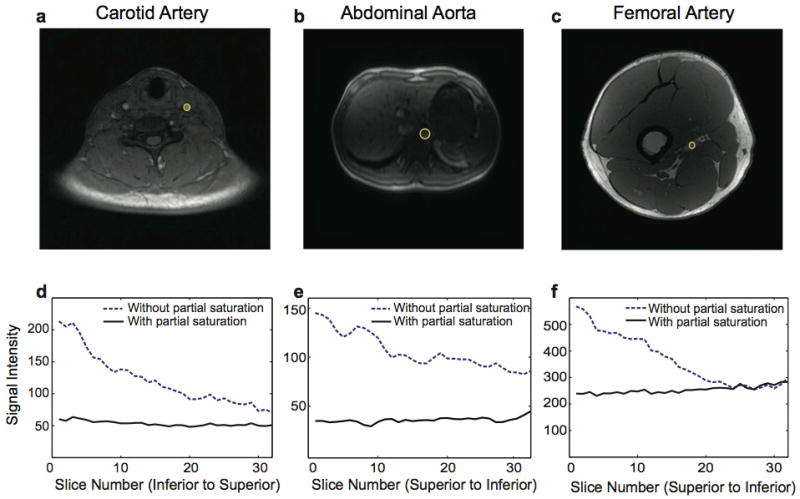
In vivo images and signal intensity variation across the arteries. Axial neck (a), abdomen (b), and leg (c) images, and signal intensity changes over regions of interest in the carotid artery (d), abdominal aorta (e), and femoral artery (f) are shown. Using partial saturation, inflow enhancement is eliminated for all three arteries.
Discussion
Partial saturation effectively eliminates flow artifacts including inflow enhancement and pulsatile ghost artifacts in RF-spoiled gradient-echo imaging. Compared to the standard RF-spoiled imaging sequence, one additional RF pulse and set of spoiler gradients are required per repetition. Although this increases the TR, this work focuses on the effect of partial saturation, leaving optimizing the sequence for future development.
A spatial 90° saturation of an upstream slab is often used to reduce the blood signal and pulsatile ghost artifacts [25, 26]. However, this method is not appropriate for T1 quantification. Furthermore, compared to the partial saturation RF pulse, the full saturation RF pulse either induces a higher specific absorption rate (SAR) for a given time-bandwidth product or yields less spatial selectivity for a given pulse duration. Finally, full saturation is much more sensitive to B1 inhomogeneity than partial saturation.
By applying partial saturation to flowing spins, their longitudinal magnetization can approach the steady-state level while they are in the partial saturation slab. When spins cross the partial saturation slab into the imaging slab, some signal fluctuation might occur due to the change of the RF magnetic field. However, this fluctuation is relatively small compared to inflow-related artifacts.
As described in “Introduction”, RF spoiling eliminates coherent transverse magnetization through the destructive addition of transverse magnetization components for stationary spins. However, when spins move in the direction of spoiler gradients, additional phase accumulation occurs for those spins [18]. If flow is steady, spins actually experience a quadratic phase increase over sequence repetitions [27], and thus the effective quadratic phase increment each spin experiences is the original RF phase increment, plus the flow-related phase increment. This can possibly alter the steady-state signal level. However, if flow is pulsatile, additional phases are incoherent over sequence repetitions similar to those from random variation of RF phases [28, 29]. In this case, the formation of coherent transverse magnetization is still avoided, and signal contrast is similar to that with ideal spoiling. Thus, our use of the z spoiler gradient for dephasing the partial saturation slab actually helps to spoil transverse magnetization and achieves accurate T1 contrast for pulsatile flow as our phantom experiments have demonstrated.
The magnetization simulation with pulsatile flow is a simplified case to illustrate practical situations. Realistically, spins do not simply move in one direction. In addition, at a given cardiac phase, spins at different locations have varying velocities since the flow velocity pattern is normally laminar within a cross-section of vessel. Therefore, there exists incoherence in both the flow direction and velocity among different spins within a voxel. We think that the magnetization variations from different spins tend to average out within a voxel, reducing view-to-view signal fluctuations in practical situations. Our phantom and in vivo experiments support this hypothesis because ghost artifacts that occur due to view-to-view signal fluctuation are minimal when partial saturation is used.
The thickness of the partial saturation slab determines the number of times for which inflowing spins experience the RF pulses before entering the imaging slab, and thus the degree to which inflow enhancement is reduced. For complete elimination of inflow enhancement, the partial saturation slab should be thick enough for spins to experience a sufficient number of RF pulses. Theoretically, when the TR is 20 msec and the flip angle is 20°, approximately 60 RF pulses are needed for blood to attain the steady state in longitudinal components. For blood with a mean velocity of 25 cm/s, a 30 cm thick partial saturation slab is necessary. This is achievable with the body coil, which provides a homogenous excitation range of 40–50 cm. However, a very thick partial saturation slab is not desirable because it widens the transition band. Another approach might be to use a spatially varying flip angle profile within the partial saturation slab. If a larger flip angle is used at the entry of the partial saturation slab and the flip angle is smoothly decreased to the imaging flip angle, then spins can be driven to the steady state more quickly.
Partial saturation increases the scan time for the pulse duration of one RF pulse and one spoiler gradient. When the scan time is critical, the TR can be reduced by using different types of RF pulses. For example, using a maximum-phase RF pulse for the partial saturation instead of a minimum-phase RF pulse can decrease the spoiler gradient area after the partial saturation RF pulse since the slab-select gradient itself can provide more gradient spoiling. For further reduction, two RF pulses, a maximum-phase pulse and a minimum-phase pulse, can be combined as one RF pulse [30]. In that case, dephasing of the partial saturation slab is achieved by only the slab-select gradient, thus the RF pulse needs to be long with a high time-bandwidth product to provide a sufficient spoiling gradient area. However, with the variable rate selective excitation design [31], the RF pulse duration can be greatly reduced.
Conclusion
Partial saturation allows us to manipulate upstream spins to the steady-state longitudinal magnetization level without generating a net signal until they enter the imaging slab. It can reduce inflow enhancement and pulsatile ghost artifacts for 3D RF-spoiled gradient-echo sequences, producing a signal level close to pure T1 contrast across the entire slab.
Acknowledgments
Grant Sponsors: This work was supported by NIH 2P41RR009784-11, NIH R01-EB0009055, Department of Defense, the Richard M. Lucas Foundation, and General Electric Healthcare.
References
- 1.Sobol WT, Gauntt DM. On the stationary states in gradient echo imaging. J Magn Reson Imaging. 1996;6:384–398. doi: 10.1002/jmri.1880060220. [DOI] [PubMed] [Google Scholar]
- 2.Gyngell ML. The steady-state signals in short-repetition-time sequences. J Magn Reson. 1989;81:474–483. [Google Scholar]
- 3.Wood ML, Silver M, Runge VM. Optimization of spoiler gradients in FLASH MRI. Magn Reson Imaging. 1987;5:455–463. doi: 10.1016/0730-725x(87)90379-1. [DOI] [PubMed] [Google Scholar]
- 4.Frahm J, Hänicke W, Merboldt KD. Transverse coherence in rapid FLASH NMR imaging. J Magn Reson. 1987;72:307–314. [Google Scholar]
- 5.Crawley AP, Wood ML, Henkelman RM. Elimination of transverse coherences in FLASH MRI. Magn Reson Med. 1988;8:248–260. doi: 10.1002/mrm.1910080303. [DOI] [PubMed] [Google Scholar]
- 6.Wang H, Riederer S. A spoiling sequence for suppression of residual transverse magnetization. Magn Reson Med. 1990;15:175–191. doi: 10.1002/mrm.1910150202. [DOI] [PubMed] [Google Scholar]
- 7.Zur Y, Wood ML, Neuringer LJ. Spoiling of transverse magnetization in steady-state sequences. Magn Reson Med. 1991;21:251–263. doi: 10.1002/mrm.1910210210. [DOI] [PubMed] [Google Scholar]
- 8.Epstein FH, Mugler JP, III, Brookeman JR. Spoiling of transverse magnetization in gradient-echo (GRE) imaging during the approach to steady state. Magn Reson Med. 1996;35:237–245. doi: 10.1002/mrm.1910350216. [DOI] [PubMed] [Google Scholar]
- 9.Busse RF, Riederer SJ. Steady-state preparation for spoiled gradient echo imaging. Magn Reson Med. 2001;45:653–661. doi: 10.1002/mrm.1088. [DOI] [PubMed] [Google Scholar]
- 10.Preibisch C, Deichmann R. Influence of RF spoiling on the stability and accuracy of T1 mapping based on spoiled FLASH with varying flip angles. Magn Reson Med. 2009;61:125–135. doi: 10.1002/mrm.21776. [DOI] [PubMed] [Google Scholar]
- 11.Treier R, Steingoetter A, Fried M, Schwizer W, Boesiger P. Optimized and combined T1 and B1 mapping technique for fast and accurate T1 quantification in contrast-enhanced abdominal MRI. Magn Reson Med. 2007;57:568–576. doi: 10.1002/mrm.21177. [DOI] [PubMed] [Google Scholar]
- 12.Axel L. Blood flow effects in magnetic resonance imaging. Am J Roentgenol. 1984;143:1157–1166. doi: 10.2214/ajr.143.6.1157. [DOI] [PubMed] [Google Scholar]
- 13.Perman WH, Moran PR, Moran RA, Bernstein MA. Artifacts from pulsatile flow in MR imaging. J Comput Assist Tomogr. 1986;10:473–483. [PubMed] [Google Scholar]
- 14.de Graaf RG, Groen JP. MR angiography with pulsatile flow. Magn Reson Imaging. 1992;10:25–34. doi: 10.1016/0730-725x(92)90369-b. [DOI] [PubMed] [Google Scholar]
- 15.Ivancevic MK, Zimine I, Montet X, Jean-Noel H, Lazeyras F, Foxall D, Vallee JP. Inflow effect correction in fast gradient-echo perfusion imaging. Magn Reson Med. 2003;50:885–891. doi: 10.1002/mrm.10633. [DOI] [PubMed] [Google Scholar]
- 16.Peeters F, Annet L, Hermoye L, van Beers BE. Inflow correction of hepatic perfusion measurements using T1-weighted, fast gradient-echo, contrast-enhanced MRI. Magn Reson Med. 2004;51:710–717. doi: 10.1002/mrm.20032. [DOI] [PubMed] [Google Scholar]
- 17.Pang Y, Bernardo M, Turkbey B, Ravizzini G, Thomasson D, Choyke P. Minimizing inflow effects in measured arterial input function for prostate DCE-MRI. Proceedings of the 16th Annual Meeting of ISMRM; Toronto, Canada. 2008. p. 2775. [Google Scholar]
- 18.Patz S. Some factors that influence the steady state in steady-state free precession. Magn Reson Imaging. 1988;6:405–413. doi: 10.1016/0730-725x(88)90477-8. [DOI] [PubMed] [Google Scholar]
- 19.Kaiser R, Bartholdi E, Ernst RR. Diffusion and field-gradient effects in NMR Fourier spectroscopy. J Chem Phys. 1974;60:2966–2979. [Google Scholar]
- 20.Henning J. Multiecho imaging sequences with low refocusing flip angles. J Magn Reson. 1988;78:397–407. [Google Scholar]
- 21.Yuan C, Gullberg GT, Parker DL. The solution of Bloch equations for flowing spins during a selective pulse using a finite difference method. Med Phys. 1987;14:914–921. doi: 10.1118/1.596129. [DOI] [PubMed] [Google Scholar]
- 22.Gao JH, Gore JC. Effects of slow flow on slice profile and NMR signal in fast imaging sequences. Phys Med Biol. 1994;39:1489–1500. doi: 10.1088/0031-9155/39/9/013. [DOI] [PubMed] [Google Scholar]
- 23.Brey WW, Narayana PA. Correction for intensity falloff in surface coil magnetic resonance imaging. Med Phys. 1988;15:241–245. doi: 10.1118/1.596255. [DOI] [PubMed] [Google Scholar]
- 24.Denolin V, Azizieh C, Metens T. New insights into the mechanisms of signal formation in RF-spoiled gradient echo sequences. Magn Reson Med. 2005;54:937–954. doi: 10.1002/mrm.20652. [DOI] [PubMed] [Google Scholar]
- 25.Felmlee JP, Ehman RL. Spatial presaturation: a method for suppressing flow artifacts and improving depiction of vascular anatomy in MR imaging. Radiology. 1987;164:559–564. doi: 10.1148/radiology.164.2.3602402. [DOI] [PubMed] [Google Scholar]
- 26.Frahm J, Merboldt KD, Hänicke W, Haase A. Flow suppression in rapid FLASH NMR images. Magn Reson Med. 1987;4:372–377. doi: 10.1002/mrm.1910040408. [DOI] [PubMed] [Google Scholar]
- 27.Duyn JH. Steady state effects in fast gradient echo magnetic resonance imaging. Magn Reson Med. 1997;37:559–568. doi: 10.1002/mrm.1910370414. [DOI] [PubMed] [Google Scholar]
- 28.Freeman R, Hill HDW. Phase and intensity anomalies in Fourier transform NMR. J Magn Reson. 1971;4:366–383. [Google Scholar]
- 29.Lin W, Song HK. Improved accuracy in T1 mapping and flip angle correction with random spoiling in radial gradient echo imaging. Proceedings of the 17th Annual Meeting of ISMRM; Honolulu, Hawaii, USA. 2009. p. 4440. [Google Scholar]
- 30.Han M, Hargreaves BA. Combined excitation and partial saturation to reduce inflow enhancement. Proceedings of the 18th Annual Meeting of ISMRM; Stockholm, Sweden. 2010. p. 4947. [Google Scholar]
- 31.Conolly S, Nishimura D, Macovski A, Glover G. Variable-rate selective excitation. J Magn Reson. 1988;78:440–458. [Google Scholar]


