

Abstract
Background
Lymph flow depends on both the rate of lymph production by tissues and the extent of passive and active pumping. Here we aim to characterize the passive mechanical properties of a lymphangion in both mid-lymphangion and valve segments to assess regional differences along a lymphangion, as well as evaluating its structural composition.
Methods and Results
Mesenteric lymphatic vessels were isolated and cannulated in a microchamber for pressure–diameter (P-D) testing. Vessels were inflated from 0 to 20 cmH2O at a rate of 4 cmH2O/min, and vessel diameter was continuously tracked, using an inverted microscope, video camera, and custom LabVIEW program, at both mid-lymphangion and valve segments. Isolated lymphatic vessels were also pressure-fixed at 2 and 7 cmH2O and imaged using a nonlinear optical microscope (NLOM) to obtain collagen and elastin structural information. We observed a highly nonlinear P-D response at low pressures (3–5 cmH2O), which was modeled using a three-parameter constitutive equation. No significant difference in the passive P-D response was observed between mid-lymphangion and valve regions. NLOM imaging revealed an inner elastin layer and outer collagen layer at all locations. Lymphatic valve leaflets were predominantly elastin with thick axially oriented collagen bands at the insertion points.
Conclusions
We observed a highly nonlinear P-D response at low pressures (3–5 cmH2O) and developed the first constitutive equation to describe the passive P-D response for a lymphangion. The passive P-D response did not vary among regions, in agreement with the composition of elastin and collagen in the lymphatic wall.
Introduction
Lymph transport begins at the interstitium where interstitial fluid enters the initial lymphatics. Lymph is propelled onward by collecting lymphatic vessels via intrinsic and extrinsic pumping mechanisms, both relying on valves to prevent retrograde flow. Intrinsic pumping propels lymph independently through the phasic contraction/relaxation of the vessel using the muscle cells in the lymphatic wall. These lymphatic muscle cells possess some of the characteristics of both smooth and cardiac muscle cells. Extrinsic pumping, on the other hand, refers to the compression of lymphatic vessels by surrounding tissues that deform due to limb bending, respiration, and skeletal muscle activity.
Gashev1 and Zawieja et al.2 have illustrated fluid transport by the intrinsic pump from the rat mesentery, thoracic and cervical areas. They characterize the intrinsic pump as displaying both phasic (rapid) and tonic (slow, long-lasting) contractions.2 Lymphatic vessels from skeletal tissue beds rely relatively more on extrinsic rather than intrinsic pumping.3 Both pumping mechanisms are crucial to the transport of lymph. However, there remain many unanswered questions regarding the extent of the contribution of each mechanism and the specifics of lymph flow regulation.
Collecting lymphatic vessels typically experience 40%–60% changes in diameter through a single contractile cycle, with maximum deformations of up to 85%.4.5 Given this behavior, it is important to characterize the wall mechanical properties of lymphatic vessels over a large range of deformation. The mechanical properties are a central influence on the contractile function of the lymphatics and thus the distribution of lymph volume. To date, constitutive modeling of the lymphatic vasculature has been rudimentary because of the complexity of performing experiments on lymphatic vessels and our limited knowledge of the system. The vessels are thin-walled and usually deeply embedded in tissue, and thus difficult to isolate.
The mechanical effectiveness of muscle cell contraction on deformation of a lymphatic vessel depends on the constituents and arrangement of the lymphatic wall. Recent work has shown that muscle cells are distributed nonhomogeneously in the vessel wall.1,2,6,7 Collagen and elastin are the other dominant components of the vessel wall.8,9 However, past studies of the ultrastructure of the lymphatic vessel largely ignored the mechanical properties of the vessel wall. Therefore, there is a need to characterize the active and passive mechanical properties and to relate these properties to the structure of lymphatic vessels.
Ohhashi et al.10 studied the active and passive mechanical properties of bovine mesenteric lymphatics (vessel diameter ∼3 mm) via a series of pressure–volume and pressure–radius relations. Their findings suggested that smooth muscle cells play a role in the elastic behavior of the lymphangion by increasing the elastic modulus (i.e., stiffening of vessel). Further, the authors state that spontaneous activity of lymphatic smooth muscle is regulated not only by stretch but also by the rate of deformation, suggesting that passive viscoelastic properties may be relevant to active physiological behavior. However, they did not describe their findings in a constitutive equation. Venugopal et al.11 published a mathematical model describing the nonlinear pressure–volume relation of lymphatic vessels with a piecewise-linear function. While this is a good first approximation, functions with continuous derivatives are closer in spirit to the biology and more suitable for purposes such as network modeling. Numerous models have been developed for arterial microcirculatory networks and the roles of myogenic, shear, and metabolic responses in the autoregulation of blood flow.12–14 However, none of these models have been adapted to describe the regulation of lymph flow.
In this study, we characterize the passive properties of rat mesenteric lymphatic vessels by means of pressure–diameter tests. We propose an equation to describe the passive pressure-diameter relationship of the lymphatic wall at the valve and the two adjacent straight segments (i.e., upstream and downstream of the valve) along the axis of a lymphangion. Using nonlinear optical microscopy, we also examine the distribution of collagen and elastin at these three regions of interest, in order to relate the structural composition of the wall to the mechanics of the lymphangion.
Materials and Methods
Vessel isolation
Male Sprague-Dawley rats (150–300 g) were anesthetized with an intraperitoneal injection of sodium pentobarbital (60 mg/kg) and a loop of intestine was exteriorized. Lymphatic vessels of diameter 80–180 μm were dissected from the mesentery and placed in albumin physiological saline solution (APSS) at room temperature. The APSS contained (in mM) 145.0 NaCl, 4.7 KCl, 2.0 CaCl2, 1.2 MgSO4, 1.2 NaH2PO4, 0.02 EDTA, 5.0 glucose, 2.0 sodium pyruvate, 3.0 3-(N-morpholino) propanesulfonic acid, and 0.5 g/100 ml purified bovine serum albumin, adjusted to pH 7.4 at 37°C. All chemicals were obtained from Sigma (St. Louis, MO) except albumin (product #10856, U.S. Biochemicals, Cleveland, OH). A mesenteric venule and arteriole of comparable size were also isolated from a single rat for comparison. Animals were subsequently euthanized with Nembutal (120 mg/kg). All animal protocols were approved by the University of Missouri and Texas A&M Health Science Center Animal Care and Use Committees and conformed to the Public Health Service Policy for the Humane Care and Use of Laboratory Animals (PHS Policy, 1996).
Isolated lymphatic segments with one valve were cannulated at each end with a glass micropipette, filled with APSS (∼3 mL chamber) and held in a Lucite holder mounted on a Burg-style V-track system.15 The apparatus was then transferred to the stage of an inverted microscope (Inverted Zeiss ACM equipped with Zeiss 3.2x and 6.3x objectives). Input and output pressures (Pin and Pout, respectively) were initially set from standing reservoirs and the axial length of the vessel was adjusted so that there was no slack in the vessel with Pin and Pout temporarily set to ∼13 cmH2O; this ensured no buckling of the vessel at higher pressures. A continuous flow of heated APSS through the chamber (2 ml/min) prevented changes in osmolarity associated with evaporation.
Pressure–diameter protocol
A high-resolution (0.5–1 μm/pixel; 1624×510 pixels) fire-wire camera (model A641FM, Basler AG, Ahrensburg, Germany) controlled by an in-house LabVIEW (version 2009, National Instruments, Austin, TX) program was used to acquire high-resolution video of the entire pressure–diameter experiment, including measurements of internal vessel diameter and inlet and outlet pressures.4 The vessel image was digitized at 28–30 Hz. Pin and Pout were measured using low-pressure transducers (model 104, CyberSense, Nicholasville, KY) and digitized (model PCI 6030e A/D card, National Instruments) in synchrony with diameter data. Each lymphatic vessel was allowed to equilibrate and exhibit spontaneous contractions at 37°C before the start of experimentation to ensure normal behavior. The chamber bath was flushed and replaced with nominally Ca2+-free physiologic saline (CaCl2 was replaced with 3 mM EDTA). Pin and Pout were then ramped up from 0 to 20 cmH2O at a constant rate of ∼4 cmH2O/min to give the passive pressure–diameter curve. A total of 9 mesenteric lymphatic vessels, 1 venule, and 1 arteriole were tested.
Video post-processing
The video images from all experiments were recorded in an AVI file along with embedded pressure and diameter data, so that all the measured parameters could be replayed and reprocessed off-line. The video was compressed (5:1) without degrading the image quality using a lossless Lagarith video codec. Three sites along the vessel were investigated: upstream of the valve, at the valve sinus, and downstream of the valve. Internal diameters measured from the video images were normalized with respect to each region's respective maximum passive diameter (at pressure 20 cmH2O) and plotted against pressure (See supplementary video clips at www.liebertpub.com/lrb.)
Modeling passive response
Passive pressure–diameter relations were fitted using the equations below:
 |
(Eq. 1) |
 |
(Eq. 2) |
where P0 is the pressure scaling parameter, Sp is the sharpness parameter indicative of the sharpness of the bend in the curve, D is vessel diameter, and D0 is the normalizing value of D (i.e., vessel diameter at pressure 20 cmH2O from our experiments). The exponential term represents the increasing stiffness at higher pressures and the cubic term models the collapsible behavior at low pressures, which obeys tube law.16 A nonlinear least squares regression analysis was performed in Matlab (version 2010b, MathWorks Inc., Natick, MA) to obtain the best-fit coefficients for each region of interest; P0 and Sp were bounded so that their values remained positive. Parameter values were then compared for each region (upstream, valve, downstream) to determine if there was any regional variation.
Fixed vessel preparation
Lymphatic vessels were isolated from the rat mesentery and pressure-fixed at low and high pressures (2 and 7 cmH2O, respectively) with formalin and/or formaldehyde and then stored in physiologic saline solution (PSS) at 4°C until imaging. The vessels were mounted in 2.4% agarose wells, such that the vessel was straight and the valve could be easily viewed. Efforts were made to mount the vessels at the same level of axial stretch. The vessels were submerged in PBS while imaging at room temperature.
Nonlinear optical microscopy
The custom-built NLOM system has been described previously.17 Briefly, sub-10 femtosecond pulses (800 nm peak wavelength, 133 nm full width at half maximum) from a Kerr lens mode-locked Ti:Al2O3 oscillator (Femtosource, Femtolasers, Vienna, Austria) pumped by a frequency-doubled Nd:YVO4 solid-state laser (Verdi, Coherent, Santa Clara, CA) were coupled into an epifluorescence port of an upright microscope (Axioskop2 MAT, Carl Zeiss, Thornwood, NY) via dual-axis galvanometer-driven mirrors (Cambridge Technology, Lexington, MA). The laser beam was directed to the microscope objective (20x Achroplan, numerical aperture 1.0, water immersion, Carl Zeiss) by a short-pass dichroic mirror (635dcspxruv3p, Chroma, Rockingham, VT). Nonlinear optical signals were directed by the objective through one of two accessory ports on the binocular head to a custom-built dual-channel detector housing two dichroic mirrors and band-pass filters (Chroma), focusing lenses (31-2321, Linos Photonics, Milford, MA), and a pair of photon-counting photomultiplier tubes (R7400P, Hamamatsu, Bridgewater, NJ). Second harmonic generation (SHG) and two photon fluorescence (TPF) signals were separated with a long-pass dichroic mirror (430dcxru, Chroma) and band-pass filters (HQ405/40 and HQ480/40, respectively, Chroma). Photomultiplier tubes were connected to a pre-amplifier/discriminator (F-100T, Advanced Research Instruments, Golden, CO), which compared signal current with a threshold and thereby converted it to transistor-transistor logic pulses for photon counting. The entire NLOM system was mounted on a vibration-isolated optical table. We imaged each vessel at three locations: 250–300 μm upstream of the valve, at the valve sinus, and 250–300 μm downstream of the valve with a 0.5 μm z-step (i.e., imaged through the entire vessel from top to bottom). Average imaged segments were 250 μm in length and average lymphangion lengths were ∼750 μm. SHG and TPF signal components were imaged and segmented simultaneously to obtain images of fibrillar collagen (types I and III) and elastin, respectively.18,19 The resolution of the NLOM was between 0.4 and 0.5 μm.
In situ histochemical staining
To confirm the TPF signal obtained for elastin, we utilized an alternate approach, staining elastin with Alexa-633 hydrazide as previously described by Clifford et al.20 Briefly, pressurized lymphatic vessels were fixed (4% paraformaldehyde) and stained with the elastin-selective Alexa Fluor 633 hydrazide (0.2 mmol/L, excitation 633/emission 700 nm) and Alexa Fluor 488 hydrazide (0.2 mmol/L, excitation 488/emission 700 nm) which binds a broader range of extracellular matrix proteins, including both elastin and collagen. Through-focus 3D image stacks were collected by confocal microscopy (0.3 mm Z-steps) at each emission wavelength and image reconstruction used to visualize collagen and elastin fibers within the lymphatic vessel wall.
Image processing
Matlab (version 2010b, MathWorks Inc.) and ImageJ (NIH) were used to process the image stacks obtained from the NLOM. Images were converted from 16 to 8 bits of contrast and the signals from the SHG and TPF were isolated to represent the collagen and elastin components, respectively. Median and Gaussian filters were used to remove noise, and image stacks were normalized to the maximum pixel intensity to allow for appropriate comparison. Full-width half-maximum calculations of each signal were performed to obtain collagen and elastin layer thickness through the wall from the central plane of the vessel. Wall thickness was averaged along the entire length of the imaged section (both edges).
Statistical analysis
The coefficients obtained from the best fits were recorded and are presented in Table 1 as the mean±standard error of the mean (SEM). We evaluated differences between coefficients from the three areas (valve sinus, upstream, and downstream) for statistical differences using a paired Student t-test with Bonferroni correction (95% confidence level).
Table 1.
Best-Fit Parameters for the Passive Pressure–Diameter Three-Parameter Model (Eq. 2)
| P0 (cmH2O) | Sp | D0 (μm) | |
|---|---|---|---|
| Upstream | 18.0±0.6 | 20.4±5.3 | 157.4±7.7 |
| Valve | 17.3±0.7 | 21.7±2.9 | 179.2±10.8 |
| Downstream | 18.1±0.7 | 24.6±2.5 | 174.6±10.8 |
Results are reported as mean±SEM.
Results
Lymphatic vessels exhibited a highly nonlinear pressure–diameter response at very low pressures compared to the mesenteric arteriole and venule of comparable size (Fig. 1). Lymphatic vessels exhibited a sharp stiffness transition around 5 cmH2O, whereas the venule demonstrated a more gradual transition between 10 and 15 cmH2O; the arteriole did not exhibit a notable transition within the pressure range shown here (Fig. 1).
FIG. 1.

Pressure–diameter relations of three representative vessels. A lymphatic vessel (green circles), a venule (blue triangles), and an arteriole (red squares) of comparable size were isolated from the mesentery of a single rat. Vessel diameter was normalized with respect to the maximum diameter (lymphatic 267 μm, venule 278 μm, and arteriole 135 μm). The lymphatic vessel operates at the lowest pressure range (0–5 cmH2O), approximately one-third of the venule pressure range, and exhibits the sharpest transition from low to higher pressures, clearly seen in the inset (zoomed in to pressure values of 0–20 cmH2O). These results are similar to Zhang et al.28 (A color version of this figure is available in the online article at www.liebertpub.com/lrb.)
The passive properties of the lymphangions were modeled with the three-parameter equation described in the Methods section (Eq. 2). The exponential model presented as Equation 1 was only used for comparison to the established model for arterioles developed by Carlson et al.12 (Supplementary Fig. S1; supplementary data are available online at www.liebertonline.com/lrb). The mean values (±SEM) for P0 and Sp across all regions were 17.7±0.6 cmH2O and 22.2±2.6, respectively. Similarly, average D0 values (i.e., max vessel diameter at pressure 20 cmH2O) were 166.5±5.1 μm. The parameter values for each region are listed in Table 1. There was a slight increase in the mean value of Sp, as the measurement site moved from the upstream to downstream regions of the vessel. However, statistical analysis did not reveal any significant differences between regions (p>0.05). The curve fits obtained with the three-parameter model had R2>0.9; representative curve fits for one vessel are shown in Figure 2.
FIG. 2.

Passive curve fits at four regions along a lymphangion. Regions 1 and 2 correspond to upstream locations (260 μm and 170 μm from the valve, respectively), Region 3 is at the valve site, and Region 4 is 200 μm downstream of the valve.
Images from the nonlinear optical microscope revealed that the valve leaflet was predominantly elastin, with collagen and elastin throughout the rest of the vessel wall in a distinct outer/inner layer arrangement. The leaflets of the bicuspid valves were predominantly elastin but with thick collagen bands oriented in the axial direction at the insertion points and buttresses (i.e., locations where the valve meets the vessel wall). As expected, collagen fiber structures were more undulated in vessels fixed at low pressure (2 cmH2O) than at high pressures (7 cmH2O) (Figs. 3–8). Collagen layer thickness was 7.4 μm on average and, given the limited system resolution and number of specimens, no significant change in collagen layer thickness with increasing pressure was detected. However, elastin layer thickness decreased from 11.1 μm in vessels fixed at low pressure to 8.2 μm in vessels fixed at high pressure, on average (Table 2). Two photon fluorescence of elastin was confirmed with elastin staining using Alexa-633 hydrazide. Clifford et al.20 have previously demonstrated that Alexa-633 hydrazide selectively binds to elastin in cremaster muscle arterioles. Lymphatic vessels stained with Alexa-633 hydrazide expressed elastin fibers in the valve leaflets and along the inner wall of the vessel (Fig. 9).
FIG. 3.

NLOM images of the upstream segment at low pressure. The pressure-fixed vessel (p=2 cmH2O) is imaged 250 μm upstream of the valve. (A) SHG signal representing collagen structure, (B) TPF signal representing elastin, and (C) overlaid images of SHG and TPF signals (collagen in green, elastin in red). Each slice is ∼7 μm apart. Vessel diameter ∼90 μm. (A color version of this figure is available in the online article at www.liebertpub.com/lrb.)
FIG. 8.

NLOM images of the downstream segment at high pressure. The pressure-fixed vessel (p=7 cmH2O) was imaged 250 μm downstream of the valve. (A), (B), and (C) as in Figure 3. Each slice is ∼7 μm apart. Vessel diameter ∼112 μm. (A color version of this figure is available in the online article at www.liebertpub.com/lrb.)
Table 2.
Summary of Collagen and Elastin Layer Thicknesses from a Single Lymphatic Vessel at Low (P=2 cmH2O) and High Pressures (P=7 cmH2O)
| |
Pressure=2 cmH2O |
Pressure=7 cmH2O |
||
|---|---|---|---|---|
| Collagen Thickness (μm) | Elastin Thickness (μm) | Collagen Thickness (μm) | Elastin Thickness (μm) | |
| Upstream | 7.4 | 10.7 | 7.0 | 6.6 |
| Valve | 7.6 | 11.4 | 6.0 | 9.0 |
| Downstream | 7.2 | 11.3 | 9.4 | 9.0 |
| Average | 7.4 | 11.1 | 7.5 | 8.3 |
FIG. 9.
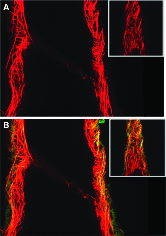
Complementary approach for staining of extracellular matrix proteins in lymphatic vessels. Lymphatic vessels were fixed and pressurized (P=7 cmH2O) and stained with Alexa Fluor 633 hydrazide staining of elastin (red) and Alexa Fluor 488 hydrazide staining of elastin and collagen (green). Yellow/orange indicates overlap in which both dyes bind elastin. (A) shows 633 excitation image alone with elastin fibers along the vessel wall and valve leaflet. (B) shows the combined 633 and 488 nm excitation image, again illustrating the elastin fibers in the leaflet and collagen in the outer vessel wall. Note the lack of collagen in the valve leaflets, in agreement with the TPF and SHG signals from NLOM. Inserts show the vessel from the outer surface from which the vessel was subsequently optically sectioned. Lymphatic vessel diameter=158 μm at the valve, pressure=7 cmH2O. Typical of n=3. (A color version of this figure is available in the online article at www.liebertpub.com/lrb.)
FIG. 4.

NLOM images of the valve segment at low pressure. The pressure-fixed vessel (p=2 cmH2O) is imaged at the valve. (A), (B), and (C) as in Figure 3. Each slice is ∼7 μm apart. Vessel diameter ∼110 μm. Note the thick collagen bands at the valve insertion points and predominant elastin signal from the valve leaflets. (A color version of this figure is available in the online article at www.liebertpub.com/lrb.)
FIG. 5.

NLOM images of the downstream segment at low pressure. The pressure-fixed vessel (p=2 cmH2O) is imaged 250 μm downstream of the valve. (A), (B), and (C) as in Figure 3. Each slice is ∼7 μm apart. Vessel diameter ∼90 μm. (A color version of this figure is available in the online article at www.liebertpub.com/lrb.)
FIG. 6.

NLOM images of the upstream segment at high pressure. The pressure-fixed vessel (p=7cmH2O) is imaged 275 μm upstream of the valve. (A), (B), and (C) as in Figure 3. Each slice is ∼7 μm apart. Vessel diameter ∼110 μm. (A color version of this figure is available in the online article at www.liebertpub.com/lrb.)
FIG. 7.

NLOM images of the valve segment at high pressure. The pressure-fixed vessel (p=7cmH2O) is imaged at the valve. (A), (B), and (C) as in Figure 3. Each slice is ∼7 μm apart. Vessel diameter ∼110 μm. (A color version of this figure is available in the online article at www.liebertpub.com/lrb.)
Discussion
Expanding our knowledge of basic mechanical characteristics of a lymphangion is essential for elucidating modes of regulation of lymph transport. There have been few attempts at characterizing the mechanical properties of lymphangions. Most have been in larger vessels (0.5–3 mm in diameter), and analysis has been more or less qualitative (e.g., Ohhashi et al.10). None have developed a constitutive equation or related the mechanical behavior to structural components. This is partly due to the difficulties in performing mechanical tests and histology on such small, thin-walled vessels. In this study, we successfully imaged the collagen and elastin fiber structure of rat mesenteric lymphatic vessels using NLOM, and used pressure–diameter data to develop an equation characterizing the passive properties of a lymphangion.
We showed that lymphatic valves are composed of elastin and almost devoid of collagen. Collagen was observed only at the insertion points and buttresses of the valves and at the outer wall of the vessel, suggesting that this regional differentiation provides structural support for the valve leaflets and vessel. The buttresses are believed to support the leaflets, allowing rapid and complete closure of the valve during retrograde flow while preventing valve inversion (Mazzoni et al.,21). Previous studies on lymphatic valve structure yielded mixed results. Vajda et al.8 and Gnepp et al.9 claimed to detect elastin in the lymphatic valves; however, other studies reported only an endothelial layer on the valve leaflets and no elastin.22,23 Skalak et al.3 showed that lymphatic valves in the spinotrapezius muscle of the rat had collagen on both sides, along with endothelial cells. Albertine et al.24 observed only collagen fibrils and fibroblasts in canine lymphatic valves. They detected no smooth muscle cells, nerve fibers, or elastin in the valves. We believe that some of these discrepancies may be attributed to the sensitivity of the methods used in these studies (e.g., histological sectioning, light microscopy, scanning electron microscopy, and transmission electron microscopy) and the levels of elastin being difficult to detect. NLOM allows for the imaging of a live and/or fixed vessel without any staining and hence is advantageous for evaluating collagen and elastin structure in fully intact lymphatic vessels. We did, however, verify that our TPF signal correlated to Alexa-633 hydrazide staining of elastin (Fig. 9).
Similar to blood vessels, the lymphangion wall can be described as a three-layer structure, with an intimal lining of endothelial cells, a thicker medial layer containing elastin and variable layers of muscle cells, and an adventitial layer of collagen fibers. This follows a previous study,25 which showed a thick, continuous elastic lamina beneath the endothelium, surrounded by several thin layers of muscle cells within the elastic lamina. Although we did not stain smooth muscle cells in this study, numerous reports from Zawieja's group have shown that smooth muscle cells are oriented circumferentially in the lymphatic wall. They report fewer smooth muscle cells in the valve sinus region compared to upstream and downstream segments.2,7 However, we observed no significant changes in the average collagen or elastin layer thickness across these regions of the lymphangion. The only change we observed was a decrease in elastin layer thickness with increasing pressure (from 2 to 7 cmH2O), which is indicative of the incompressible nature of the vessel. The collagen layer thickness should have also decreased, but we did not detect a significant change anywhere along the vessel, probably due to the NLOM's limited resolution (∼0.4 μm). The only observed decrease in collagen layer thickness (from 7.6 to 6 μm) was at the valve site. Based on our results, we describe the nonvalvular regions of lymphatic vessels as cylindrical tubes composed of an inner elastin layer and outer collagen mesh.
In addition to characterizing the structural organization of lymphatic vessels, we developed a three-parameter equation for the passive mechanical response of lymphatic vessels. Unlike its equivalent in previous equations for the passive properties of arterioles (Eq. 1, Carlson and Secomb12 Carlson et al.,13), our constitutive relation incorporates a cubic term, which describes the collapsible nature of the vessel at low and negative transmural pressures. If the compliant nature of the vessel at intermediate pressures (which one can think of as the inverse of the slope of the curves in Fig. 1) were maintained as pressure approached zero, that would imply that the vessel could eventually reach negative diameters, which would not make sense. Although our tests from this study did not cover negative transmural pressures, its inclusion makes the model more physiologic since lymphatic vessels are more prone to experience excess external pressure than arterioles.4
Further, the exponential equation used to describe the pressure–diameter relationship (Eq. 1) is valid in the positive transmural pressure range when there is no muscular activity. In cases where either the transmural pressure is negative or significant lymphatic SMC contraction occurs, the exponential function fails to describe vessel behavior accurately (Supplementary Fig. 1). As is well known from the collapsible tube dynamics literature, tubular structures begin to depart from their circular cross-section at negative pressures and ultimately experience opposite-wall contact,26 consequently exhibiting a decrease in compliance. In these situations, it is appropriate to include “tube law” description, which can be as simple as adding a polynomial to the exponential shown in Equation 2.
Our pressure–diameter curves are qualitatively similar to the findings of Ohhashi et al.,10 who performed pressure–radius and pressure–volume tests on bovine mesenteric lymphatics, and observed higher distensibility at lower luminal pressures. Our results suggest that normal operating pressures for a lymphatic vessel are between 0 and 5 cmH2O and that lymphatic vessels become effectively indistensible conduits at pressures greater than 5 cmH2O. The stiffness transition at this threshold was sharper than that seen by Ohhashi et al.10 in larger vessels and a different species. Venugopal et al.11 used the latter data in fitting a combination of two straight lines to the pressure–volume relationship of a relaxed lymphangion. We believe that our constitutive equation is superior for future models of lymph flow in that it has continuous derivatives.
Our results further show that passive properties of lymphatic vessels from the rat mesentery do not vary significantly across the lymphangion regions. This result parallels the relatively homogeneous distribution of collagen and elastin observed from the NLOM images. However, given the inhomogeneous distribution of muscle cells in a lymphangion,2,7 there could be regional differences in the active pressure–diameter response of the vessel. Furthermore, there may be differences in the extent of lymphangion regional variation between mesenteric lymphatics and larger collecting ducts (e.g., thoracic duct) and even more variation between species. For example, Lobov27 described a more rigid valvular portion in bovine mesenteric lymphatic vessels. We believe that his results are attributable to both the larger vessel diameter and the greater smooth muscle component of those lymphatic vessels. Assessing the effects of muscle tone on lymphatic properties would provide crucial information to develop an active model for the regulation of lymph flow.
Conclusion
In conclusion, we developed a three-parameter constitutive equation characterizing the passive pressure–diameter response of a small lymphatic vessel. We showed that lymphatic vessel elastic properties exhibit sharp nonlinearity at very low pressures, unlike that of arterioles and venules of similar size in the same pressure range. Lymphatic valve leaflets were shown to be predominantly composed of elastin and more limited amounts of collagen at selected locations. This work clearly illustrates the nature of the compliance of small lymphatic vessels and provides a solid foundation for further lymphatic modeling. In future work, we plan to investigate the effects of muscle tone to obtain an active and total pressure-diameter response for lymphatic vessels.
Supplementary Material
Acknowledgments
We would like to acknowledge Wei Wang and Zhanna Nepiyushchikh for isolating and pressure-fixing the vessels used for NLOM imaging. Thanks are extended to Aaron Stupica for assistance with confocal imaging studies. CDB is grateful to Laboratoire d'Hydrodynamique, Ecole Polytechnique, France, for affording sabbatical facilities. Funding came from NIH R01 HL094269 (JEM), NIH HL070308 (DZ) and HL-089784 (MJD).
Author Disclosure Statement
No competing financial interests exist.
References
- 1.Gashev AA. Lymphatic vessels: Pressure- and flow-dependent regulatory reactions. Ann NY Acad Sci. 2008;1131:100–109. doi: 10.1196/annals.1413.009. [DOI] [PubMed] [Google Scholar]
- 2.Zawieja DC. von der Weid PY. Gashev AA. Comprehensive Physiology. John Wiley & Son; New Jersey: 2011. Microlymphatic Biology; pp. 125–158. [Google Scholar]
- 3.Skalak TC. Schmid-Schönbein GW. Zweifach BW. New morphological evidence for a mechanism of lymph formation in skeletal muscle. Microvasc Res. 1984;28:95–112. doi: 10.1016/0026-2862(84)90032-3. [DOI] [PubMed] [Google Scholar]
- 4.Davis MJ. Rahbar E. Gashev AA. Zawieja DC. Moore JE., Jr Determinants of valve gating in collecting lymphatic vessels from rat mesentery. Am J Physiol Heart Circ Physiol. 2011;301:H48–60. doi: 10.1152/ajpheart.00133.2011. [DOI] [PMC free article] [PubMed] [Google Scholar]
- 5.Dixon JB. Greiner ST. Gashev AA. Cote GL. Moore JE. Zawieja DC. Lymph flow, shear stress, and lymphocyte velocity in rat mesenteric prenodal lymphatics. Microcirculation. 2006;13:597–610. doi: 10.1080/10739680600893909. [DOI] [PubMed] [Google Scholar]
- 6.Gashev AA. Physiologic aspects of lymphatic contractile function: Current perspectives. Ann NY Acad Sci. 2002;979:178–187. doi: 10.1111/j.1749-6632.2002.tb04878.x. discussion 188–196. [DOI] [PubMed] [Google Scholar]
- 7.Zawieja DC. Contractile physiology of lymphatics. Lymphat Res Biol. 2009;7:87–96. doi: 10.1089/lrb.2009.0007. [DOI] [PMC free article] [PubMed] [Google Scholar]
- 8.Vajda J. Tomcsik M. The structure of the valves of the lymphatic vessels. Acta Anat (Basel) 1971;78:521–531. doi: 10.1159/000143611. [DOI] [PubMed] [Google Scholar]
- 9.Gnepp DR. Green FH. Scanning electron microscopic study of canine lymphatic vessels and their valves. Lymphology. 1980;13:91–99. [PubMed] [Google Scholar]
- 10.Ohhashi T. Azuma T. Sakaguchi M. Active and passive mechanical characteristics of bovine mesenteric lymphatics. Am J Physiol. 1980;239:H88–95. doi: 10.1152/ajpheart.1980.239.1.H88. [DOI] [PubMed] [Google Scholar]
- 11.Venugopal AM. Stewart RH. Laine GA. Quick CM. Nonlinear lymphangion pressure–volume relationship minimizes edema. Am J Physiol Heart Circ Physiol. 2010;299:H876–882. doi: 10.1152/ajpheart.00239.2009. [DOI] [PMC free article] [PubMed] [Google Scholar]
- 12.Carlson BE. Secomb TW. A theoretical model for the myogenic response based on the length-tension characteristics of vascular smooth muscle. Microcirculation. 2005;12:327–338. doi: 10.1080/10739680590934745. [DOI] [PubMed] [Google Scholar]
- 13.Carlson BE. Arciero JC. Secomb TW. Theoretical model of blood flow autoregulation: Roles of myogenic, shear-dependent, and metabolic responses. Am J Physiol Heart Circ Physiol. 2008;295:H1572–1579. doi: 10.1152/ajpheart.00262.2008. [DOI] [PMC free article] [PubMed] [Google Scholar]
- 14.Zulliger MA. Fridez P. Hayashi K. Stergiopulos N. A strain energy function for arteries accounting for wall composition and structure. J Biomech. 2004;37:989–1000. doi: 10.1016/j.jbiomech.2003.11.026. [DOI] [PubMed] [Google Scholar]
- 15.Duling BR. Gore RW. Dacey RG., Jr Damon DN. Methods for isolation, cannulation, and in vitro study of single microvessels. Am J Physiol. 1981;241:H108–116. doi: 10.1152/ajpheart.1981.241.1.H108. [DOI] [PubMed] [Google Scholar]
- 16.Flaherty JE. Keller JB. Rubinow SI. Post buckling behavior of elastic tubes and rings with opposite sides in contact. SIAM J Appl Math. 1972;23:446–455. [Google Scholar]
- 17.Larson AM. Yeh AT. Ex vivo characterization of sub-10-fs pulses. Opt Lett. 2006;31:1681–1683. doi: 10.1364/ol.31.001681. [DOI] [PubMed] [Google Scholar]
- 18.Cox CS., Jr Radhakrishnan R. Villarrubia L. Xue H. Uray K. Gill BS. Stewart RH. Laine GA. Hypertonic saline modulation of intestinal tissue stress and fluid balance. Shock. 2008;29:598–602. doi: 10.1097/SHK.0b013e318157eba7. [DOI] [PubMed] [Google Scholar]
- 19.Zoumi A. Lu X. Kassab GS. Tromberg BJ. Imaging coronary artery microstructure using second-harmonic and two-photon fluorescence microscopy. Biophys J. 2004;87:2778–2786. doi: 10.1529/biophysj.104.042887. [DOI] [PMC free article] [PubMed] [Google Scholar]
- 20.Clifford PS. Ella SR. Stupica AJ. Nourian Z. Li M. Martinez-Lemus LA. Dora KA. Yang Y. Davis MJ. Pohl U. Meininger GA. Hill MA. Spatial distribution and mechanical function of elastin in resistance arteries: A role in bearing longitudinal stress. Arterioscler Thromb Vasc Biol. 2011;31:2889–2896. doi: 10.1161/ATVBAHA.111.236570. [DOI] [PMC free article] [PubMed] [Google Scholar]
- 21.Mazzoni MC. Skalak TC. Schmid-Schönbein GW. Structure of lymphatic valves in the spinotrapezius muscle of the rat. Blood Vessels. 1987;24:304–312. doi: 10.1159/000158707. [DOI] [PubMed] [Google Scholar]
- 22.Takada M. The ultrastructure of lymphatic valves in rabbits and mice. Am J Anat. 1971;132:207–217. doi: 10.1002/aja.1001320207. [DOI] [PubMed] [Google Scholar]
- 23.Bloom W. Fawcett DW. A Textbook of Histology. Ninth. W. E. Saunders Co.; Philadelphia: 1968. [Google Scholar]
- 24.Albertine KH. Fox LM. O'Morchoe CC. The morphology of canine lymphatic valves. Anat Rec. 1982;202:453–461. doi: 10.1002/ar.1092020404. [DOI] [PubMed] [Google Scholar]
- 25.Bannykh S. Mironov A., Jr Bannykh G. Mironov A. The morphology of valves and valve-like structures in the canine and feline thoracic duct. Anat Embryol (Berl) 1995;192:265–274. doi: 10.1007/BF00184751. [DOI] [PubMed] [Google Scholar]
- 26.Shapiro AH. Steady flow in collapsible tubes. ASME J Biomechan Engineer. 1977;99:126–147. [Google Scholar]
- 27.Lobov GI. [The rheological properties of the large lymphatic vessels] Fiziol Zh SSSR Im I M Sechenova. 1990;76:371–377. [PubMed] [Google Scholar]
- 28.Zhang RZ. Gashev AA. Zawieja DC. Davis MJ. Length–tension relationships of small arteries, veins and lymphatics from the rat mesenteric microcirculation. Am J Physiol Heart Circ Physiol. 2007;292:H1943–1952. doi: 10.1152/ajpheart.01000.2005. [DOI] [PubMed] [Google Scholar]
Associated Data
This section collects any data citations, data availability statements, or supplementary materials included in this article.