Abstract
Background
Ventricular remodeling deteriorates myocardial function in congestive heart failure patients. Ventricular restraint therapy using Cardiac Support Device (CSD) is designed to reduce the amount of stress inside the dilated ventricles which in turn halts remodeling. However, as an open mesh surrounding the heart, it is unknown what the mechanical properties of the CSD are in different fiber orientations.
Methods
Composite specimens of CorCap™ CSD fabric and silicone were constructed in different fiber orientations and tested on a custom-built biaxial stretcher. Silicone controls were made and stretched to detect parameters of the matrix. CSD coefficients were calculated using the composite and silicone matrix stress-strain data. Stiffness in different fiber orientations was determined.
Results
Silicone specimens exerted a linear behavior with stiffness of 2.57MPa. For the composites with one fiber set aligned with respect to the stretch axes, stiffness in the direction of the aligned fiber set was higher than that in the cross-fiber direction (14.39MPa vs. 5.66MPa), indicating greater compliance in the cross-fiber direction. When the orientation of the fiber sets in the composite were matched to the expected clinical orientation of the implanted CorCap, the stiffness in the circumferential axis (with respect to the heart) was greater than in the longitudinal axis (10.55MPa vs. 9.70MPa).
Conclusions
The mechanical properties of the CorCap demonstrate directionality with greater stiffness circumferentially than longitudinally. Implantation of CorCap clinically should take into account the directionality of the biomechanics to optimize ventricular restraint.
Keywords: heart failure, mechanical properties, compliance, CorCap, cardiac support device
INTRODUCTION
Heart failure (HF) is a potentially fatal pathology with an increasing incidence and economic burden during the last decades.[1] The lifetime risk of developing HF is 20% at the age of 40, and increases significantly if the patient suffers from ischemic heart disease.[2] Several approaches have been applied to prevent or treat decompensated HF, which can be categorized as: 1) resolution of the underlying cause such as coronary artery revascularization, 2) medical treatments like angiotensin-converting enzyme inhibitors and β-blockers, and 3) a wide spectrum of surgical techniques including ventricular reconstructive surgery, ventricular assist device, ventricular restraint therapy and heart transplantation.[3]
An increase in left ventricular (LV) size in patients with HF is shown to be associated with increased mortality.[4] Ventricular restraint therapy using Cardiac Support Device (CSD) is designed based on the Laplace law to reduce the amount of stress inside the dilated ventricles by externally constraining the oversized heart, which in turn halts remodeling and deterioration of HF.[5–7] Although the technique is relatively simple and does not require extracorporeal circulation, it is crucial to tighten-up the mesh to the extent that constrains the heart on one hand, but does not cause diastolic dysfunction or myocardial malperfusion on the other hand.[8] Currently, intraoperative echocardiography and real-time adjustment of CSD are used to determine the optimal restraint level [9,10], both of which are extremely surgeon-dependant. Given the open mesh design of the CSD, it is important to understand the mechanical properties of the device in different fiber orientations as the ventricular geometry is not a uniform cylinder or sphere. The biomechanical behavior of the CSD is critical to optimizing the implantation of the device. In this study, we investigated the material properties of Corcap™ CSD[10] using a combination of biaxial testing methods and a theoretical framework.
MATERIALS AND METHODS
Specimen Construction
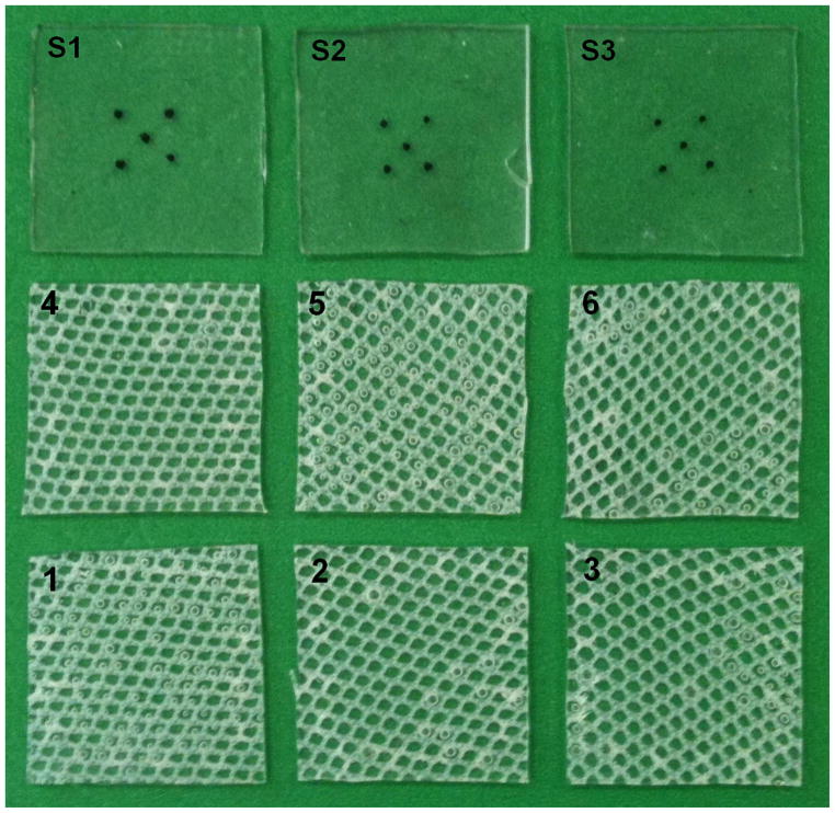
In contrast to biological tissues being routinely tested on bi-axial stretching systems, CorCap™ CSD fabric has an open mesh structure that is not homogeneous and uniform. Therefore, if CSD is tested alone, an uneven distribution of forces results, which in turn leads to a large amount of shear stress and deformation of the specimens. This open air mesh makes determination of mechanical properties using standard tensile testing methods unreliable without development of additional methods. In order to distribute the stretching forces uniformly across the specimens, we embedded the CSD jacket in an elastic silicone matrix (Sylgard 184, Dow Chemical Co., Figure 1) and subsequently were able to isolate the CSD mechanical properties as described later in the methods.[11] As such, composite specimens of CorCap™ CSD fabric and silicone were constructed and tested on a custom-built biaxial stretcher. Silicone was made by mixing a 10:1 weight fraction of the monomer:initiator as recommended by the manufacturer. Controls for the study were made at the same time using the silicone matrix alone and were of the same dimensions and thickness as the composite test specimens.
Figure 1.
Three silicone and 6 composite specimens used for biaxial stretching. Composite specimens were cut in different orientations; S1–S3, silicone specimens; 1–9, composite specimens.
Equibiaxial Stretching
A custom built planar biaxial stretcher was used. Details of system setup, procedure for data collection and analyses have been described previously.[12] Briefly, 4 stretcher arms were independently driven by four microstep motors with attached shaft encoders. Load cells (Model 31/3672-02, Honeywell Sensotec Inc., Columbus, OH, 1 kg range) mounted on two stretcher arms measured the force required to stretch the specimen.
Six CSD fabric/ silicone composites and four silicone controls were tested. All specimens were cut in square 1inch by 1inch shape and the fibers in the composite specimens were deliberately studied in different orientations with regard to the specimen edge (Figure 1). Specimen dimensions and composite weight fraction were measured using the weight of a single sheet of CSD mesh cut to the same dimension as the samples for mechanical testing.
The surface of each sample was marked with ink in a five mark 3mm x 3mm square pattern. The specimen surface was imaged using a charge-coupled device (CCD) camera placed perpendicular to the sample surface and the marker positions were digitized with a custom program (Matlab, v7.0.1, Natick, MA) and CSD fabric fiber angles relative to the Cartesian ‘X’ axis were also determined (NIH ImageJ).[13]
The distal end of each stretcher arm was attached to the sample edge using a continuous 5-0 silk suture and small fishhooks. Load cells were zeroed to ensure that there was no load on the sample prior to the testing protocol. Each sample was stretched using quasistatic equibiaxial displacement controlled protocol to a shaft encoder determined maximum displacement of 15%.
Constitutive Model
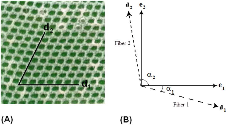
Figure 2 shows alignment of the mesh within the silicone matrix, as well as how the fiber angles were defined for the constitutive modeling. The fiber vector directions can be written as:
| (1a) |
| (1b) |
where α1 is the angle of the first set of fibers and α2 is the angle of the second set of fibers, as shown in Figure 2. Specimen 3 is shown beside it.
Figure 2.
(A) Representative CSD/Silicone composite specimen 4, and (B) general definition of fiber angles in constitutive model.
Stress was defined as a measure of the average force acting per unit of a surface within a deformable body in the deformed configuration. Pre-stress was defined as the amount of stress in the specimen at zero loading condition; i.e. before any additional load is applied. Planar forces ( f ) measured by the load cells during deformation were converted to Cauchy stresses (σ) in the principal directions, given by
| (2a) |
| (2b) |
where σ11 and σ22 are the Cauchy stresses in the e1 and e2 directions, respectively (indices 1 and 2 represent the principal stretching directions), t is tissue thickness, and λ represents the principal stretch defined as the ratio of deformed length (l1 and l2) to resting specimen length (l0). Components of Green strain (E) were calculated using the following equations
| (3a) |
| (3b) |
In order to represent the material response of the CSD jacket embedded in silicone, we employed theory from laminated fiber-reinforced composites. For this case, the response of the composite samples was decomposed into the sum of the matrix response and the fiber response. In the present work a transversely isotropic, hyperelastic, incompressible strain energy function W was used:
| (4) |
where F1 represents the behavior of the matrix component (neo-Hookean model) and F2 represents the contribution from the fibers (Fung-type exponential).[14] After differentiating the strain energy function, and using a plane stress assumption for the samples, the membrane Cauchy stress for the bi-directional composite structure can be written as:
| (5a) |
| (5b) |
where C1 is the material constant for the matrix; α1 is the angle of the first set of fibers and α2 is the angle of the second set of fibers; λf1 and λf2 are the stretches in fiber direction 1 and 2, respectively; C3,1 and C4,1 are the fiber material constants for the first set of fibers; and C3,2 and C4,2 are the fiber material constants for the second set of fibers. The main advantages of this approach is that the material model can be used to represent the response of the CSD alone simply by reducing the value of C1, which eliminates the influence from the matrix material.
Data Analyses
Biaxial data from the control and composite experiments were fit to the stress-strain relation defined in equation 5. A Genetic Algorithm was employed to determine the optimal set of material parameters that minimized the difference between the predicted and experimental stress-strain curves, i.e. minimized (R2 – 1) for each set of curves, where R2 is the coefficient of determination. A Genetic Algorithm is an intelligent searching technique that can be used to minimize an objective function without the need for taking the gradient, which makes the technique very versatile. Details about the method can be found in the work by Zohdi and Wriggers.[15] In the present study, the parameter C1 was determined from the control samples by fitting the data to a neo-Hookean model, which is the first term in equation 5. Then, holding C1 fixed, the parameters associated with the fiber component of the composites were determined for equation 5 (C3,1, C4,1, C3,2, and C4,2). Each optimization was conducted by successively refining the search area until the parameter values were unchanged. MATLAB software (v7.0.1, Natick, MA) was used for optimization analyses. Specimen stiffness was defined as the first derivative of stressstrain response at a given point.
RESULTS
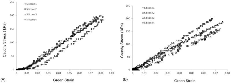
Cauchy stress-Green strain curves for silicone specimens are depicted in Figure 3. The mechanical behavior of silicone specimens was completely linear as expected. It was consistent among the four different specimens as well as between the two orthogonal directions for each individual specimen, with an average stiffness of 2.57MPa. Silicone specimens were stretched up to a maximum extention of 10%, at which point the samples tore mainly at the site of hook insertion. An average constant of 445kPa was best fit to the mechanical behavior of the silicone matrix and used for determination of the CSD jacket parameters (C1 in equation 5).
Figure 3.
Cauchy Stress/Green Strain plots after equibiaxial stretching of the silicone specimens in the two orthogonal orientations; direction 1 (A) and direction 2 (B).
The CSD composite specimens could be stretched to higher extensions before failure (15% vs. 10%, Figure 4). Also, the CSD fabric had a significant influence on the stiffness. Data from the 2 composite specimens that were oriented with one fiber set aligned with respect to the stretch direction (composites 1 and 4) were consistent and showed higher stiffness in the direction of the aligned fibers. Data from the remaining 4 specimens which did not have a fiber set aligned with the orthogonal axes (composites 2, 3, 5, and 6) displayed moderate stiffness.
Figure 4.
Cauchy Stress/Green Strain plots for all six CSD composite specimens after equibiaxial stretching in the two orthogonal directions; (A) direction 1and (B) direction 2.
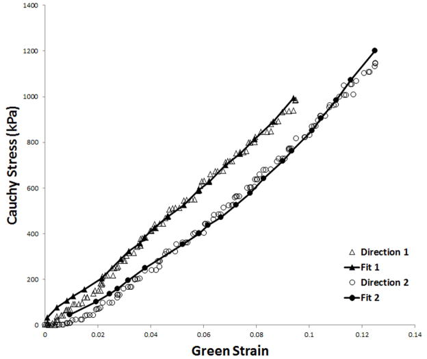
Figure 5 shows the accuracy of fit for one representative CSD composite specimen (composite 6). Note that both of the fiber sets capture much of the silicone matrix response at the lowest stretches. However, the composite material response at higher stretches is dominated by the properties of the fibers of the CSD fabric.
Figure 5.
Experimentally obtained Cauchy stress/Green Strain data for representative CSD composite specimen 6 with one fiber family aligned with the direction of stretch. The calculated fit curves are shown as solid lines.
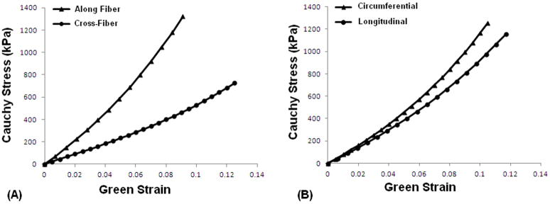
Optimized coefficients in equations 5a and 5b for each CSD composite specimen are reported in Table 1. For the composites with one fiber set aligned with respect to the stretch axes (i.e. composites 1 and 4) coefficient C4,1, representing the term in the direction of the aligned fiber set, was higher than C4,2 which corresponds to the cross-fiber direction (14.1 vs. 10.7 and 12.4 vs. 9.05 respectively), indicating greater compliance in the cross-fiber direction (an average stiffness of 14.39MPa vs. 5.66MPa). In Figure 6A representative curves are plotted based on the average coefficients and angles for composites 1 and 4, showing higher compliance in the cross-fiber direction. Fiber sets in composites 5 and 6 were oriented in a way that closely matched the recommended orientation of the CorCap when it is implanted.[10] As such, the stiffness in the circumferential axis (with respect to the heart) was greater than in the longitudinal axis (C4,1 and C4,2 of 13.0 vs. 4.2 respectively for composite 5, and those of 11.5 vs. 8.9 respectively for composite 6, with an average stiffness of 10.55MPa vs. 9.70MPa). Figure 6B shows a representative fit based on the average coefficients and angles of composites 5 and 6, confirming higher stiffness in the circumferential direction compared with that in the longitudinal direction.
Table 1.
Coefficients to the strain energy function, given in equations 5a and 5b, were determined by fitting equibiaxial experimental data for silicone samples alone and those for the CSD embedded in silicone. The coefficient c was kept fixed in the optimization protocols for the composite material.
| Composite # | α1 | α2 | c1 (kPa) | c3,1 (kPa) | c4,1 | c3,2 (kPa) | c4,2 | R2, 1 | R2, 2 |
|---|---|---|---|---|---|---|---|---|---|
| 1 | −4° | 57° | 445 | 661.48 | 14.11 | 900.77 | 10.69 | 0.993 | 0.993 |
| 2 | −15° | 47° | 445 | 45.18 | 34.59 | 504.01 | 22.24 | 0.995 | 0.996 |
| 3 | −37° | 35° | 445 | 337.21 | 25.79 | 29.95 | 4.49 | 0.976 | 0.939 |
| 4 | −1° | 60° | 445 | 574.00 | 12.37 | 968.62 | 9.05 | 0.988 | 0.987 |
| 5 | −45° | 53° | 445 | 1171.42 | 13.00 | 51.75 | 4.18 | 0.984 | 0.986 |
| 6 | −50° | 40° | 445 | 1140.11 | 11.50 | 458.83 | 8.98 | 0.993 | 0.993 |
Figure 6.
Representative fit curves based on average coefficients and angles for (A) the composites with one fiber set aligned with respect to the stretch axes (i.e. composites 1 and 4), and (B) the composites oriented in a way closest to what the CorCap actually looks like when it is implanted (i.e. composites 5 and 6).
DISCUSSION
Ventricular remodeling is one of the most important mechanisms of HF progression, independent of the patient’s hemodynamic and neurohormonal status.[4,16,17] From the gross anatomical standpoint, alterations in LV geometry leads to four major pathophysiological consequences: LV chamber dilation, increased LV sphericity, LV wall thinning, and mitral valve incompetence.[18] As a result, LV wall stress dramatically increases during ventricular remodeling and places higher oxygen demands on an already burdened and failing heart, which in turn contributes to more remodeling and creates a vicious cycle. Passive ventricular restraint devices constrain the dysfunctional ventricles externally, and attempt to break the cycle by preventing further ventricular dilation and preserving its native elliptical geometry.[10]
Long-term results of the largest clinical trial of CSD, ACORN, have been encouraging especially in terms of major cardiac events and NYHA functional class.[19,20] Although not effective on the overall mortality, CorCap™ device caused a significant reduction in LV end-diastolic volume as well as a small increase in sphericity index, defined as LV end-diastolic length/width, indicating return to a more physiologic ellipsoidal shape.[19] Reverse remodeling has been shown in several studies as well.[21,22] In fact, cardiac restraint therapy leads not only to a size reduction but also restores the ellipsoidal geometry of the ventricles.[23]
Despite the promising preliminary data, concerns still remain regarding the technical details and related complications of CSD.[24] Lee et al. showed in a study that CorCap™ affects the left and right ventricles differently, and the left ventricle can tolerate more restraint than the right ventricle.[25] In order for the mesh to be beneficial for the left ventricle, it should be pre-stressed to the level that may be excessive for the right ventricle. In other words, if the fabric is too stiff or fabric pre-stress is too great, LV diastolic compliance and filling can be compromised, which eventually leads to a tamponade effect. On the other hand, in a porcine study Dixon and associates found that despite a normal steady-state hemodynamics, LV maximal coronary reserve was blunted after placement of CSD, while interestingly this adverse effect was not observed in the right ventricle.[8]
Currently, the amount of pre-stress placed on the Acorn CSD fabric at the time of implementation is poorly defined, and applied pre-stress is largely at the discretion of the cardiac surgeon. Furthermore, it is currently unknown what the CSD material properties are in different fiber orientations as that can have significant impact on the degree of ventricular restraint and give options for optimizing clinical implantation. In this study, we investigated the material properties of CorCap™ CSD using a combination of biaxial testing methods and a theoretical framework.
We modeled the effect of bi-directional reinforcement of the CorCap™ jacket in silicone using an anisotropic elasticity framework. Use of a silicone matrix in the composites resulted in a more uniform distribution of the biaxial forces across the samples. The coefficient C1 in equations 5a and 5b for the composite strain energy function represents the isotropic contribution of silicone. Using biaxial experiments, C1 was determined to be 445kPa, which was similar to that of other rubber-like materials. Although the stretch obtained in the silicone samples was lower than could be achieved using the composite materials, this did not affect our results as the silicone behavior was completely linear throughout the experiment. In other words, because the material properties of silicone are isotropic, we were able to use the value of C1 to extrapolate to higher stretches in future analyses. The relatively linear behavior of the CSD jacket in the stretch range tested was consistent with the Walsh’s study, which found that the multiaxial stiffness of the CorCap up to 12% strain is essentially linear.[10] Although they subjected the CSD to a multiaxial stress-strain testing using ball burst technique, they did not report any material constants for formulation of the CorCap characteristics and directionality.
A key issue in determining the effects of restraining devices like the CSD mesh is the compliance of the devices used.[26] In this study, we demonstrated that the stiffness of CSD is greater in the aligned fiber direction, i.e. if the sample is aligned with one of the fibers along the circumferential axis of the ventricle then the circumferential stiffness is greater than the longitudinal stiffness. However, if the CSD is aligned in the cross-fiber direction, i.e. off axis, it is less stiff. These results have clinical implications respect to orienting the fibers along the heart to have optimal restraint. However, it is currently unknown what degree of restraint is optimal and what stretch ratio is required to best maintain the pressure after weeks or months. This study demonstrates the importance of directionality of fibers which would be an important aspect to follow clinically. An understanding of the strain distributions in infarcted regions, neighboring border zone, and remote myocardium-all surrounded by the passive CSD mesh network-are important for future optimization of passive constraining devices. Moreover, at the microscopic level, fibrosis is one of the most prominent characteristics of the failing myocardium [18], which can significantly change ventricular mechanical properties and should be taken into account.
The CSD mesh is comprised of open air pores when placed on the epicardial surface of the ventricles. Postmortem studies of the CSD mesh implanted in dogs have shown an average thickness of 0.59 ± 0.15 mm thick layer of collagen fibers encapsulating the mesh after three months.[27] Using CSD mesh implanted in an ovine model with myocardial infarction, Blom and coworkers have shown an increased myofibroblast cell density within the CSD accompanied by a significant highly organized matrix accumulation.[28] They hypothesize that the incorporation of contractile cells and synthesis of matrix components within the CSD may be contributing factors that help the function of the restraining device. These factors would also increase the stiffness of the composite material, comprised of the CSD jacket embedded in extracellular matrix, and shift the stress-strain curves towards the left in the long term.[29] An interesting aspect for future study may be the changes in mechanical properties of the CSD after implantation given not only the fiber direction in vivo but also the incorporation of matrix material within the open pores.
In summary, we determined material parameters of CSD fabric embedded in an isotropic matrix (CSD fabric/ silicone composite) by using the laws of continuum mechanics, which would otherwise be unsuitable for analyzing an open mesh. The curve fits produced by the theoretical modeling of the CSD and silicone composites show good agreement with experimental biaxial tests. The compliance of CSD fabric alone was then calculated by setting matrix material constant to a low value thereby making the matrix material very compliant. We demonstrated important differences in stiffness based on fiber directionality which would be important to follow clinically for optimization of degree of restraint. These results of mechanical behavior provide a fundamental understanding of the Acorn CSD device and may be used in future studies to optimize design and application of CSD and improve outcomes in patients with congestive heart failure.
References
- 1.Jessup M, Brozena S. Heart failure. N Engl J Med. 2003;348:2007–2018. doi: 10.1056/NEJMra021498. [DOI] [PubMed] [Google Scholar]
- 2.Roger VL, Go AS, Lloyd-Jones DM, et al. Heart disease and stroke statistics--2011 update: a report from the American Heart Association. Circulation. 2011;123:e18–e209. doi: 10.1161/CIR.0b013e3182009701. [DOI] [PMC free article] [PubMed] [Google Scholar]
- 3.Pirk J. The role of cardiac surgery in treatment of chronic heart failure. Physiol Res. 2009;58 (Suppl 2):S167–169. doi: 10.33549/physiolres.931921. [DOI] [PubMed] [Google Scholar]
- 4.Douglas PS, Morrow R, Ioli A, Reichek N. Left ventricular shape, afterload and survival in idiopathic dilated cardiomyopathy. J Am Coll Cardiol. 1989;13:311–315. doi: 10.1016/0735-1097(89)90504-4. [DOI] [PubMed] [Google Scholar]
- 5.Power JM, Raman J, Dornom A, et al. Passive ventricular constraint amends the course of heart failure: a study in an ovine model of dilated cardiomyopathy. Cardiovasc Res. 1999;44:549–555. doi: 10.1016/s0008-6363(99)00255-2. [DOI] [PubMed] [Google Scholar]
- 6.Konertz WF, Shapland JE, Hotz H, et al. Passive containment and reverse remodeling by a novel textile cardiac support device. Circulation. 2001;104:I270–275. doi: 10.1161/hc37t1.094525. [DOI] [PubMed] [Google Scholar]
- 7.Chen FY, Cohn LH. The surgical treatment of heart failure. A new frontier: nontransplant surgical alternatives in heart failure. Cardiol Rev. 2002;10:326–333. doi: 10.1097/00045415-200211000-00004. [DOI] [PubMed] [Google Scholar]
- 8.Dixon JA, Goodman AM, Gaillard WF, 2nd, et al. Hemodynamics and myocardial blood flow patterns after placement of a cardiac passive restraint device in a model of dilated cardiomyopathy. J Thorac Cardiovasc Surg. 2011;142:1038–1045. doi: 10.1016/j.jtcvs.2010.09.065. [DOI] [PMC free article] [PubMed] [Google Scholar]
- 9.Ghanta RK, Lee LS, Umakanthan R, et al. Real-time adjustment of ventricular restraint therapy in heart failure. Eur J Cardiothorac Surg. 2008;34:1136–1140. doi: 10.1016/j.ejcts.2008.07.013. [DOI] [PubMed] [Google Scholar]
- 10.Walsh RG. Design and features of the Acorn CorCap Cardiac Support Device: the concept of passive mechanical diastolic support. Heart Fail Rev. 2005;10:101–107. doi: 10.1007/s10741-005-4637-x. [DOI] [PubMed] [Google Scholar]
- 11.Jones RM. Mechanics of Composite Materials. 2. Philadelphia, PA: Taylor & Francis, Inc; 1999. [Google Scholar]
- 12.Gundiah N, Ratcliffe MB, Pruitt LA. Determination of strain energy function for arterial elastin: Experiments using histology and mechanical tests. J Biomech. 2007;40:586–594. doi: 10.1016/j.jbiomech.2006.02.004. [DOI] [PubMed] [Google Scholar]
- 13.Abramoff M, Magelhaes P, Ram S. Image processing with ImageJ. Biophotonics International. 2004;11:36–42. [Google Scholar]
- 14.Quapp KM, Weiss JA. Material characterization of human medial collateral ligament. J Biomech Eng. 1998;120:757–763. doi: 10.1115/1.2834890. [DOI] [PubMed] [Google Scholar]
- 15.Zohdi TI, Wriggers P. Introduction to Computational Micromechanics. Berlin: Springer; 2005. [Google Scholar]
- 16.Vasan RS, Larson MG, Benjamin EJ, Evans JC, Levy D. Left ventricular dilatation and the risk of congestive heart failure in people without myocardial infarction. N Engl J Med. 1997;336:1350–1355. doi: 10.1056/NEJM199705083361903. [DOI] [PubMed] [Google Scholar]
- 17.Cohn JN. Structural basis for heart failure. Ventricular remodeling and its pharmacological inhibition. Circulation. 1995;91:2504–2507. doi: 10.1161/01.cir.91.10.2504. [DOI] [PubMed] [Google Scholar]
- 18.Mann DL, Bristow MR. Mechanisms and models in heart failure: the biomechanical model and beyond. Circulation. 2005;111:2837–2849. doi: 10.1161/CIRCULATIONAHA.104.500546. [DOI] [PubMed] [Google Scholar]
- 19.Mann DL, Kubo SH, Sabbah HN, et al. Beneficial effects of the CorCap cardiac support device: five-year results from the Acorn Trial. J Thorac Cardiovasc Surg. 2012;143:1036–1042. doi: 10.1016/j.jtcvs.2011.06.014. [DOI] [PMC free article] [PubMed] [Google Scholar]
- 20.Starling RC, Jessup M, Oh JK, et al. Sustained benefits of the CorCap Cardiac Support Device on left ventricular remodeling: three year follow-up results from the Acorn clinical trial. Ann Thorac Surg. 2007;84:1236–1242. doi: 10.1016/j.athoracsur.2007.03.096. [DOI] [PubMed] [Google Scholar]
- 21.Speziale G, Nasso G, Piancone F, et al. One-year results after implantation of the CorCap for dilated cardiomyopathy and heart failure. Ann Thorac Surg. 2011;91:1356–1362. doi: 10.1016/j.athoracsur.2011.02.006. [DOI] [PubMed] [Google Scholar]
- 22.Saavedra WF, Tunin RS, Paolocci N, et al. Reverse remodeling and enhanced adrenergic reserve from passive external support in experimental dilated heart failure. J Am Coll Cardiol. 2002;39:2069–2076. doi: 10.1016/s0735-1097(02)01890-9. [DOI] [PubMed] [Google Scholar]
- 23.Lembcke A, Dushe S, Dohmen PM, et al. Early and late effects of passive epicardial constraint on left ventricular geometry: ellipsoidal re-shaping confirmed by electron-beam computed tomography. J Heart Lung Transplant. 2006;25:90–98. doi: 10.1016/j.healun.2005.02.025. [DOI] [PubMed] [Google Scholar]
- 24.George TJ, Arnaoutakis GJ, Shah AS. Surgical treatment of advanced heart failure: alternatives to heart transplantation and mechanical circulatory assist devices. Prog Cardiovasc Dis. 2011;54:115–131. doi: 10.1016/j.pcad.2011.04.001. [DOI] [PubMed] [Google Scholar]
- 25.Lee LS, Ghanta RK, Mokashi SA, et al. Ventricular restraint therapy for heart failure: the right ventricle is different from the left ventricle. J Thorac Cardiovasc Surg. 2010;139:1012–1018. doi: 10.1016/j.jtcvs.2009.09.064. [DOI] [PubMed] [Google Scholar]
- 26.Gummert JF, Rahmel A, Bossert T, Mohr FW. Socks for the dilated heart. Does passive cardiomyoplasty have a role in long-term care for heart failure patients? Z Kardiol. 2004;93:849– 854. doi: 10.1007/s00392-004-0160-7. [DOI] [PubMed] [Google Scholar]
- 27.Chaudhry PA, Mishima T, Sharov VG, et al. Passive epicardial containment prevents ventricular remodeling in heart failure. Ann Thorac Surg. 2000;70:1275–1280. doi: 10.1016/s0003-4975(00)01755-0. [DOI] [PubMed] [Google Scholar]
- 28.Blom AS, Mukherjee R, Pilla JJ, et al. Cardiac support device modifies left ventricular geometry and myocardial structure after myocardial infarction. Circulation. 2005;112:1274–1283. doi: 10.1161/CIRCULATIONAHA.104.499202. [DOI] [PubMed] [Google Scholar]
- 29.Dell’Amore A, Botta L, Asioli S, Leone O, Arpesella G. Postmortem examination of the CorCap device: macroscopic and microscopic findings. Cardiovasc Pathol. 2007;16:61–62. doi: 10.1016/j.carpath.2006.08.002. [DOI] [PubMed] [Google Scholar]


