Abstract
The bacterial flagellum is a motility organelle that consists of a rotary motor and a helical propeller. The flagella usually work individually or by forming a loose bundle to produce thrust. However, the flagellar apparatus of marine bacterium MO-1 is a tight bundle of seven flagellar filaments enveloped in a sheath, and it has been a mystery as to how the flagella rotate smoothly in coordination. Here we have used electron cryotomography to visualize the 3D architecture of the sheathed flagella. The seven filaments are enveloped with 24 fibrils in the sheath, and their basal bodies are arranged in an intertwined hexagonal array similar to the thick and thin filaments of vertebrate skeletal muscles. This complex and exquisite architecture strongly suggests that the fibrils counter-rotate between flagella in direct contact to minimize the friction of high-speed rotation of individual flagella in the tight bundle within the sheath to enable MO-1 cells to swim at about 300 µm/s.
Keywords: flagellar basal body, magnetotactic motility
The bacterial flagellum is an organelle for motility consisting of three parts: the basal body that spans the cell envelope and works as a rotary motor; the helical filament that serves as a propeller; and the hook that acts as a universal joint connecting these two to transmit motor torque to the propeller (1). The motor drives the rotation of the long, helical filamentous propeller at hundreds of hertz to produce thrust that allows bacteria to swim in liquid environments. Multiple flagella can operate collectively to determine the direction of locomotion or to produce more thrust for swimming in viscous environment. Based on their arrangement, bacteria are classified into four groups: monotrichous (having one flagellum), amphitrichous (single flagellum at both ends), lophotrichous (numerous flagella as a tuft), and peritrichous (flagella distributed all over the cell except at the poles). For peritrichously flagellated bacteria, such as Escherichia coli and Salmonella, their swimming pattern alternates between “run” and “tumble” (1, 2). During a run, the motor rotates counterclockwise (as viewed from the distal end of the filament), and several flagellar filaments form a loose bundle to propel the cell. When the motor reverses its rotation to clockwise, the bundle falls apart to make the cell tumble.
MO-1 is a magnetotactic bacterium capable of orienting its cell body along the geomagnetic field lines by using magnetosomes (3). The MO-1 cell has a flagellar apparatus with two lophotrichous bundles. In contrast to peritrichously flagellated bacteria, MO-1 cells swim constantly in a helical trajectory toward magnetic north, and the trajectory changes from right-handed to left-handed without changes in velocity or direction (4). The cells are able to swim as fast as 300 µm/s, which is nearly 10-fold faster than E. coli and Salmonella. Although the flagella of the other types of bacteria usually work individually or by forming a loose bundle to produce thrust, the flagellar apparatus of MO-1 is a tight bundle of seven flagella enveloped in a sheath made of glycoproteins (5). This unique architecture appears to be essential for the smooth and high-speed swimming of MO-1. However, little is known about their spatial organization and how they coordinate their movement. To understand the mechanism of MO-1 flagellar motility, we used electron cryotomography (ECT) to analyze the 3D structure of the flagellar apparatus. We found a highly well-ordered organization of the flagella and fibrils in an intertwined hexagonal array similar to the one formed by the thick and thin filaments of vertebrate skeletal muscle. This architecture suggests that the fibrils counter rotate between the flagella to minimize their rotational friction within the tight bundle to facilitate high-speed rotation.
Results and Discussion
Components of the Flagellar Apparatus.
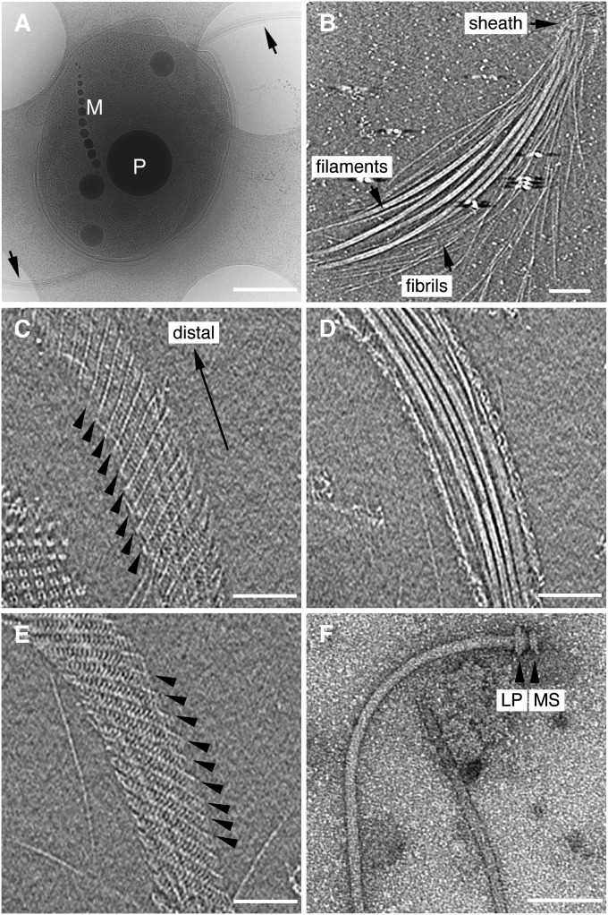
As shown in the image of a frozen-hydrated MO-1 cell by electron cryomicroscopy (cryoEM) (Fig. 1A), the cell body is typically shaped like an egg with a size of 2 µm by 1.5 µm in diameter. The cell has two curved flagellar bundles at each end of the longer dimension, as indicated by the arrows, and contains a single magnetosome chain (labeled M) and several black spheres identified as phosphorous oxygen-rich granules (labeled P). In most cells the sheath envelopes the flagellar bundle over its entire length. However, the sheath can be easily degraded or detached from the cell by centrifugation of the cells. The loss of the sheath results in the dispersion of the flagella and fibrils (Fig. 1B) and impairs cell motility. Thus, the flagellar apparatus of MO-1 is a complex structure composed of many flagellar filaments and fibrils forming a tight bundle within the sheath. Thus, the sheath plays an essential role in thrust production driven by flagellar rotation. This architecture is also a unique observation, showing that the fibrils are essential part of the flagellar apparatus.
Fig. 1.
CryoEM observation of an MO-1 cell and its flagellar apparatus. (A) CryoEM image of a vitrified MO-1 cell showing two flagellar apparatus (arrows). A phosphorous oxygen-rich granule is labeled P, and magnetosome crystals are labeled M. (Scale bar, 500 nm.) (B) A slice of a tomogram showing the distal end of a flagellar bundle where flagellar filaments and fibrils are exposed out of the sheath. (Scale bar, 100 nm.) (C–E) Three slices of a tomogram showing the structure of the sheath and the bundle of flagella and fibrils within it. The slice distance is 30.7 nm from C to D and 16.5 nm from D to E. (C) Lower surface of the sheath. (D) Middle section of the bundle. (E) Upper surface of the sheath. Arrowheads in C and E indicate the helical lines of the sheath. (Scale bars, 100 nm.) (F) Negatively stained EM image of an isolated filament-hook-basal body complex. The L, P, and MS rings are indicated. (Scale bar, 100 nm.) The tomogram was reconstructed from a tilt-series of cryoEM images over a range of ± 62°, with an increment of 2°.
The diameter of the sheath decreases toward the distal end of the flagella. CryoEM images of the sheath show that the diameter is about 130 nm in its proximal portion, about 100 nm in the middle, and 80–90 nm in the distal region. In some sheaths, the distal region is even as narrow as 70 nm. We have also seen sheaths that are narrower in the middle and become wider again at the distal tip. These changes in size suggest that the sheath is flexible in its shape and size. The 3D ECT image of the intact sheath attached to the cell shows a clear helical structure. A tomographic slice along the lower surface of the sheath (Fig. 1C) shows a set of helical lines rising from left to right, as indicated by the arrows, whereas a slice along the upper surface (Fig. 1E) shows identical helical lines rising from right to left. The middle slice (Fig. 1D) simply shows a bundle of flagella with the sheath visible at both edges. The helical lines are eight-stranded, with an axial repeat of 31.3 nm. There is also a less-prominent but finer repeat along the helical lines with an average period of 7.7 nm. These images indicate that the sheath is a tubular structure formed by a left-handed helical array of subunits. Both helical repeat distances show some variation along the circumference of the sheath as well as along its axial position. This finding is partly because of the curvature of the flagella, suggesting that the sheath is a tube made of a flexible net that can be deformed and stretched to fit over what it envelops just as a nylon stocking envelops a leg.
The individual flagella, as components of the MO-1 flagellar apparatus, can be obtained by the purification method used for E. coli and Salmonella flagella (6, 7). EM images of negatively stained specimens (Fig. 1F) show a structure similar to those of E. coli and Salmonella typhimurium (6, 7), with a filament, a hook, and a basal body with L, P, and MS rings. The filament is gently curved, about 12 nm in diameter and 3 μm in length. The filament diameter is significantly smaller than that of Salmonella, which is about 23 nm. The MO-1 strain genome encodes 12 flagellin paralogs and 2 putative flagellins, and 12 flagellins are found in the flagellar filament (8). The surface of the filament appears smooth and lacks the helical pattern observed in the filament of S. typhimurium (2). The section corresponding to the hook is straight and it is typically about 17 nm in diameter and 29 nm in length, compared with the 18 nm diameter and 55 nm length of the Salmonella hook. The size of the combined L and P rings is slightly larger than that of Salmonella, but that the size of the MS ring is similar. The L and P rings are associated with the outer membrane and the peptidoglycan layer, respectively, and the MS ring is associated with the inner membrane. The fibril (Fig. 1B) is about 2 nm in diameter and 3 μm in length. The surface of the fibril is very smooth and does not show any helical structure.
Architecture of the Flagellar Apparatus.
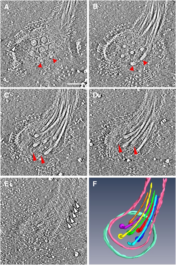
To obtain more-detailed structural information on the basal part of the flagellar apparatus, we detached the flagellar apparatus from the cell body by mechanical shearing and analyzed it by ECT. Fig. 2 A–E show five selected slices ascending from a lower to an upper position of a tomogram of a flagellar apparatus. The flagellar bundle extends from the base toward the upper right of the images, which is more clearly shown in Fig. 2F. In this image, the flagellar apparatus is viewed from outside of the cell. The bottom slice (Fig. 2A) shows the flagellar basal bodies at the base of the apparatus. As the slice goes upward, the images reveal a flagellar bundle with many fibrils (Fig. 2 B–D). The upper surface of the helical sheath appears just as seen in Fig. 1E.
Fig. 2.
Architecture of the flagellar apparatus detached from the cell body. (A–E) Five selected slices of a tomogram from lower to upper positions. The slice distance is 18.9 nm from A to B, and 9.44 nm from B to C, C to D, and D to E. The flagellar apparatus is viewed from outside of the cell. (Scale bar, 100 nm.) (A) Slice showing seven flagellar basal bodies in the hexagonal array. Each basal body shows the L and P ring and the rod within the rings. The upper five are clear, but the bottom two, indicated by red arrowheads, are only partially visible in this slice. The edge of the base platform is indicated by a white arrowhead. (B) Slice showing the proximal end of flagella in the hexagonal array. Two arrowheads indicate the ends from which two flagella are extend upward. (C and D) Slices showing the flagella and fibrils. Fibrils are indicated by red arrowheads. (E) Slice showing the upper surface of the sheath. White arrowheads indicate the helical lines shown in Fig. 1E. (F) Solid surface rendered by 3D segmentation of the seven flagella, part of the sheath, and the edge of the base platform. The tomogram was reconstructed from a tilt-series of cryoEM images from −50° to 70° with an increment of 2°.
The seven basal bodies are arranged in a highly ordered hexagonal array with one basal body at the center and the other six surrounding it with equal spacing. The center-to-center distance between the basal bodies is ∼60 nm. The basal bodies appear to be embedded in a thick, disk-like plate, which we call the base platform. Part of the circular edge of this platform can be seen in Fig. 2 A–C. In the bottom slice (Fig. 2A), each basal body shows a core density consisting of a concentric ring with a diameter of 28 nm and an axial length of 17 nm. These structures are likely to be the rod, which serves as a drive shaft, and the L and P rings, which serve as a bushing, respectively. We can also see numerous fibrils originating from the base of the flagellar apparatus (Fig. 2 B–D), as indicated by the absence of fibrils in the bottom slice (Fig. 2A). However, it was difficult to count the number of fibrils by segmentation, because they are very thin and interwoven with the seven flagella. Solid-surface rendering of the tomogram by segmentation (Fig. 2F) clearly shows a 3D image of the flagellar apparatus with the basal region and a bundle of seven flagella, which are not in physical contact with one another at the base but are more closely packed and interwoven in the distal part. This arrangement suggests that the flagellar filaments are in close physical contact with fibrils between them.
Base Platform on the Cell Envelope.
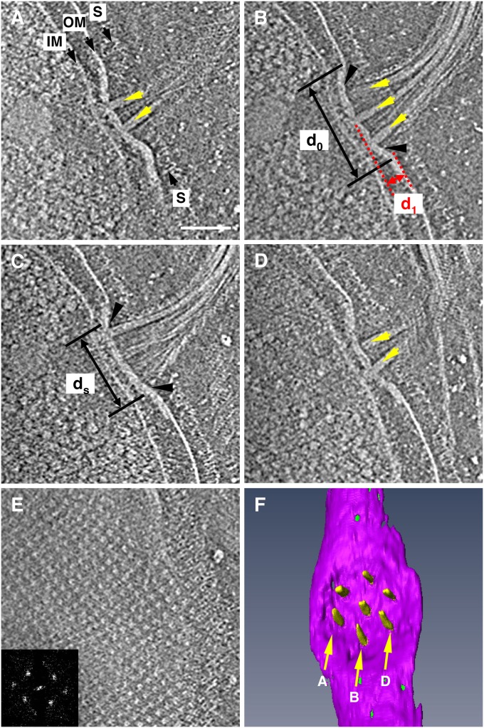
To see the architecture of the base platform and the flagellar bundle emerging and extending from it on the cell envelope, we reconstructed 3D ECT images of the intact flagellar apparatus attached to the cell envelope by ECT. Four selected slices are shown in Fig. 3 A–D, arranged from the bottom to the top of the tomogram. The slices show two (Fig. 3A), three (Fig. 3 B and C), and two flagella (Fig. 3D), indicating their arrangement in the hexagonal array. The disk-like base platform is much thicker than the outer membrane (OM), which is directly connected to the base platform. The distance between the OM and inner membrane (IM) within the platform area is reduced to approximately half of the distance seen in other areas of the cell envelope (Fig. 3 A–D). The sheath is connected to the platform surface, as indicated by black arrowheads (Fig. 3 B and C). The diameter of the sheath attached to the platform (ds in Fig. 3C) is about 160 nm. The platform is not a flat disk but is rather like a shallow bowl with a diameter of 230 nm (d0 in Fig. 3B) and a depth of 46 nm (d1 in Fig. 3B). Segmentation of the platform and flagella (Fig. 3F) reveals that the seven flagella are indeed organized in a manner corresponding to the hexagonal array observed on the platform.
Fig. 3.
Side view of an intact flagellar apparatus on the cell envelope of a vitrified MO-1 cell. (A–E) Five selected slices of a tomogram from lower to higher positions. The slice distance is 40.1 nm from A to B, 16.5 nm from B to C, 26.0 nm from C to D, and 47.2 nm from D to E. In A, the cytoplasmic membrane, outer membrane, and S-layer are labeled IM, OM, and S, respectively. The points at which the sheath attaches to the disk-like platform are indicated by black arrows in B and C. Slice through the S-layer is shown in E, with its Fourier transform in the Inset. (Scale bar, 100 nm.) (F) Solid surface rendered by 3D segmentation of the base platform and hexagonal array of seven flagella viewed from outside of the cell. Arrows labeled A, B, and D indicate the position of slices shown in panels A, B, and D, respectively. The tomogram was reconstructed from a tilt-series of cryoEM images from −62° to 58° with an increment of 2°.
A slice at a much higher position in the same tomogram (Fig. 3E) indicates that the MO-1 cell has a surface layer (S-layer) with an ordered square-lattice structure. The lattice spacing is 19.7 nm, and the distance between the S-layer and the OM is 24 nm.
Arrangement of Basal Body Rings.
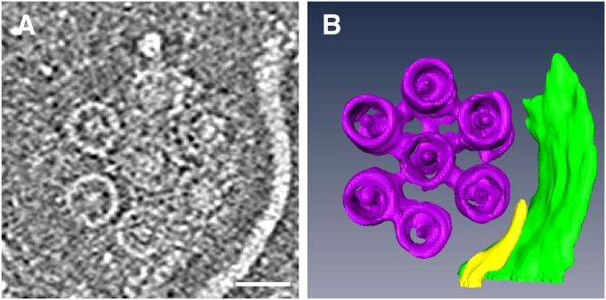
To see the structure of the basal body in more detail, we isolated the base part by shearing and reconstructed the 3D ECT image. A slice of one such tomogram is shown in Fig. 4A. Seven basal body rings are arranged in a hexagonal array with a center-to-center distance of 60 nm. The size of the ring varies slightly from slice to slice. The diameter of the ring is about 44 nm, which is approximately the same as that of Salmonella basal body C ring (2), and it increases to 50 nm as the slices approach the membrane plane, probably because of the attachment to the MS ring. The tomogram shows a small concentric ring with a diameter of 27 nm, which is similar to that of the Salmonella MS ring. In addition, there is a density at the center of the 44-nm ring that could represent part of the flagellar type III protein export apparatus; thus, this is presumably the structure of the flagellar apparatus around the cytoplasmic membrane. Segmentation of the tomogram (Fig. 4B) clearly shows how the C ring and MS ring are organized.
Fig. 4.
Structure of the flagellar basal body around the cytoplasmic membrane of isolated base platform. (A) Slice showing seven large rings, each with a central core density. (Scale bar, 50 nm.) (B) Solid surface rendered by 3D segmentation of the tomogram. The tomogram was reconstructed from a tilt-series of cryoEM images in a range of ± 62° with an increment of 2°.
Fine Structure of the Base Platform.
To study the structure of the base platform in finer detail, we isolated it by detergent solubilization. Negatively stained EM images of the sample (Fig. 5) again showed a hexagonal array of seven rings, each with a central core density, just as seen in Fig. 2. The diameter of the ring is 28 nm, and the distance between the rings is 60 nm. These two values are in good agreement with what we observed for the seven rings in the hexagonal array on the base platform (Fig. 2), indicating that this is the EM image of the isolated platform. In some cases, one of the seven flagella, complete with its L, P, and MS rings, remain in position within the hexagonal array can also be observed (Fig. S1), further supporting the conclusion that these are images of the base platform with a hexagonal array of seven L and P rings with a central core density that represents the rod.
Fig. 5.
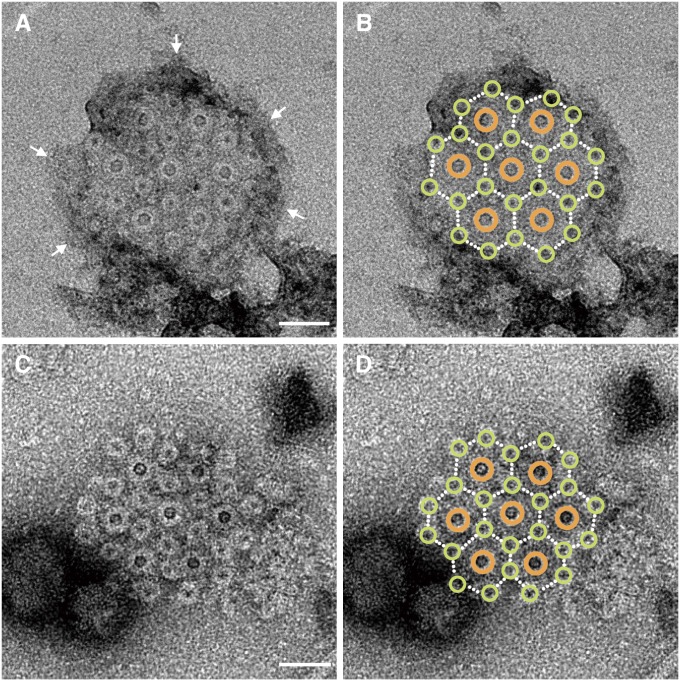
Intertwined hexagonal array of the basal bodies of 7 flagella and 24 fibrils. (A) Negatively stained EM image of a detergent-solubilized base platform. The outer membrane is indicated by arrows. (Scale bar, 50 nm.) (B) The same image as A with large brown and small yellow-green circles overlaid on the flagellar and fibril basal bodies, respectively. (C) The same as A but treated with a basic solution of pH 11. (Scale bar, 50 nm.) (D) The same image as C with the same overlays as B.
In the EM images of this preparation, an additional 24 small rings are observed. The diameter of these rings is 17 nm. These small rings form an intricate hexagonal 2D array such that each of the seven large rings is surrounded by six of the small rings (Fig. 5 A and C). This intertwined hexagonal array can be more easily recognized in Fig. 5 B and D, in which brown and yellow-green circles are superimposed onto the large and small rings, respectively. Each of the six small rings located within the area covered by the seven rings is positioned at the center of a triangle formed by three of the seven rings. Remarkably, this lattice is exactly the same as that formed by the myosin-based thick filaments and actin-based thin filaments in the cross section of vertebrate skeletal muscle fiber (9), in which the positions of the thick and thin filaments correspond to those of the large and small rings, respectively. However, in the base platform structure of the MO-1 flagellar apparatus there are only seven large rings instead of the extensive 2D hexagonal array of the thick filaments in muscle fibers.
The disk-like layer appears to be maintained in Fig. 5A, but it is gone in Fig. 5C, probably because of the treatment of that sample with a basic solution. Still, the intertwined hexagonal array of the 7 large rings and 24 small rings is maintained in Fig. 5C, suggesting that a protein scaffold connects these rings in the array, as can be less clearly observed in Fig. 4B. As mentioned before, the fibrils can be traced down to the base platform (Fig. 2) but not further inside the cell. Thus, the 24 small rings are likely to be the basal bodies of the fibrils. If so, then the seven flagella and the 24 fibrils are held together in a highly ordered, intertwined hexagonal array.
The intertwined hexagonal array of the thick and thin filaments in muscle fibers are optimized for the interactions of myosin heads and actin filaments to generate a sliding force for muscle contraction. The intertwined hexagonal array of the 7 flagella and 24 fibrils, which form a tight bundle within the sheath, must be optimized for high-speed rotation of each flagellum within the tight bundle.
Flagellar Rotation in the Tight Bundle.
Our present cryoEM study revealed a highly organized architecture of the flagellar apparatus of MO-1. Instead of being a simple helically wound propeller driven by a rotary motor, it is a complex organelle consisting of 7 flagella and 24 fibrils that form a tight bundle enveloped by a glycoprotein sheath. The flagellar basal bodies are arranged in a hexagonal array in the disk-like base platform on the cell envelope. Each flagellum possesses a basal body with L, P, MS, and C rings, just like the flagella isolated from Gram-negative bacteria. Our ECT images show that all seven flagella within a bundle extend outward without intertwining with one another. Therefore, the flagella of MO-1 must rotate individually, and yet the entire bundle functions as a unit to comprise a motility organelle.
It remains unclear how individual flagellar filaments can rotate at such high speed within the tightly packed sheathed bundle, within which the fibrils between the flagella are all in physical contact with the filaments. This organization is totally different from the one observed in the bundle of peritrichous flagellar filaments of E. coli and Salmonella, which form a loose, rotating bundle, held together by hydrodynamic interactions to produce sufficient thrust for motility. The MO-1 cells swim as fast as 300 μm/s, which is more than 100 body-lengths per second. The synchronized rotation of seven flagella in a tight bundle must allow a rapid rotation of a propeller of larger diameter that can increase swimming speed. The 24 fibrils packed together with the 7 flagella and the surrounding sheath also increase the diameter of the propeller to further amplify thrust. The drag friction of a filament is proportional to the square of the diameter. The diameter of the sheathed bundle of MO-1 is about 100 nm, which is nearly eight times as large as that of the individual flagellar filament of MO-1 and about four times of those of Salmonella and E. coli. The thrust produced by the sheathed bundle would be 9.1 (64/7) times larger than an unsheathed bundle of seven filaments of MO-1, and 3.2 (16/5) times larger than a loose bundle of four to six flagella of Salmonella and E. coli. This indicates how efficient the flagellar apparatus of MO-1 is for its fast swimming.
We hypothesize that, whereas each of the seven flagella has its torque-generating motor, the 24 fibrils counter rotate between the flagellar filaments to minimize the friction that would be generated if the flagella were directly packed together in a tight bundle. A schematic diagram representing our hypothesis is presented in Fig. 6. The flagella are represented as large brown gears and the fibrils are represented as small blue-green gears. The flagella and fibrils rotate counterclockwise and clockwise, respectively, as indicated by the arrows, to minimize friction (Movie S1). Although there is no direct evidence that the fibrils can rotate freely in the opposite direction as the flagellar filaments with which they are in direct contact, we think this is the simplest interpretation to explain the superior function afforded by the complex architecture of the MO-1 flagellar apparatus.
Fig. 6.
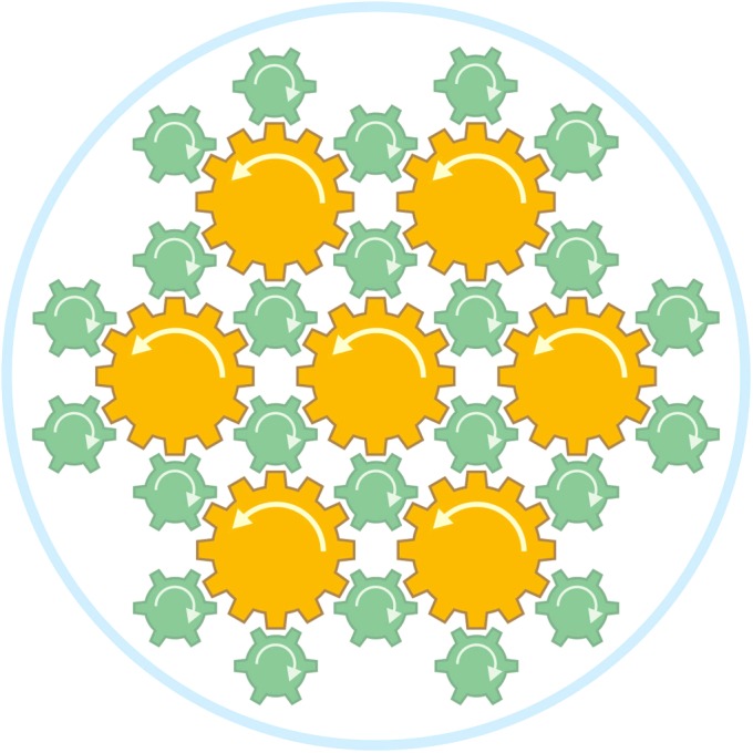
Schematic diagram showing a hypothetical mechanism for how the MO-1 flagellar apparatus might work efficiently with a tight bundle of 7 flagella and 24 fibrils encased in a sheath. The flagella are represented as large brown gears, the fibrils are represented as small blue-green gears, and the sheath is represented as the pale-blue surrounding circle. The flagella and fibrils rotate counterclockwise and clockwise, respectively, as indicated by arrows, to minimize the friction at high-speed rotation.
Considering the very tight packing of the 7 flagella and 24 fibrils that are in direct physical contact within the sheath, there appears to be no other way for the flagella to rotate at high speed without the counter rotation of the intervening fibrils. Although the fibrils and the surrounding sheath are in direct contact, the friction between them would be small because of the stocking-like flexibility of the sheath. This design must be playing an essential role in the fast, smooth rotation of the flagellar apparatus that allows the rapid swimming of MO-1.
Taken together, these features of the MO-1 flagellar apparatus represent an advanced level of evolution of a motility apparatus. It is also intriguing that the same pattern of an intertwined hexagonal array in two evolutionary distant systems: the basal bodies of flagella and fibrils of the MO-1 flagellar apparatus, and the thick and thin filaments in vertebrate skeletal muscle. Similar architectures of filamentous structures presumably evolved independently in prokaryotes and eukaryotes to fulfill the requirements for two very distinct mechanisms to generate motion: counter rotation and axial sliding.
Materials and Methods
Bacterial Strains.
The ovoid magnetotactic strain MO-1 was grown in EMS2 medium at room temperature, as described previously (4). Cell cultures used for cryo-samples were harvested after 24 h of culture growth.
Isolation of the Filament-Hook Basal Body Complex.
The isolation of the flagellar basal body was carried out as described previously (7), with several modifications. Cells were harvested after 3-d culture, centrifuged, and suspended in an ice-cold sucrose solution (0.5 M sucrose, 0.1 M Tris•HCl at pH 8.0). The cells were converted into spheroplasts at room temperature by adding lysozyme and EDTA to final concentrations of 0.1 mg/mL and 10 mM, respectively. The solution was incubated for about 30 min at room temperature to ensure the complete digestion of peptidoglycan layer. The resulting spheroplasts were lysed by the addition of Triton X-100 to a final concentration of 1% (vol/vol). To reduce the viscosity of the lysed samples, MgSO4 was added to a final concentration of 10 mM. After incubating for 60 min at room temperature, EDTA was added to a final concentration of 10 mM. Unlysed cells and cellular debris were removed by centrifugation (15,000 × g, 20 min), and then the pH of the supernatant was raised to 11 by adding 5 M NaOH. The lysate was centrifuged (67,000 × g, 60 min), and the pellet was suspended in 20 μL of TE buffer (10 mM Tris•HCl at pH 8.0, 5 mM EDTA).
Electron Microscopy of Negatively Stained Samples.
Samples were stained with 2% (wt/vol) uranyl acetate except for cells, for which 0.5% (wt/vol) uranyl acetate was used, on carbon-coated copper grids. Images were observed and recorded with a JEM-1011 transmission electron microscope operated at 100 kV.
Cryo-Sample Preparation.
A 20-μL cell culture was mixed with the pellet of 100 μL of 10-nm colloidal gold treated with BSA. For the mechanically sheared sample, the 20 μL cell culture was put through a syringe needle 25 times before mixing with the colloidal gold. A 2.9-μL aliquot of the mixture was applied to glow-discharged Quantifoil molybdenum grids before plunge-freezing into ethane using a FEI Vitrobot. Frozen grids were kept below −170 °C during the whole observation.
Electron Cryotomography.
Tilt series of cryoEM images were collected with a FEI Titan Krios equipped with a field-emission gun and a 4 k × 4 k Ultrascan 4000 CCD camera (Gatan). The microscope was operated at 200 kV. Total dose for each tilt series ranged from 100 to 120 e/Å2, and the defocus value was 8–10 μm. Images were recorded and binned twofold. The resulting pixel size on the specimen was 5.91 Å. Images of tilt series were binned fourfold before tomograms were reconstructed. Three-dimensional reconstructions from tilt series were generated with the IMOD package (10). Colloidal gold particles were tracked as fiducial markers to align the stack of tilted images. After the reconstruction, the contrast of the reconstructed volume was reversed. Segmentation and 3D visualization of the bundle, cell, and basal body structures were carried out manually, using software Amira, on the reversed 3D reconstructed volume.
Supplementary Material
Acknowledgments
J.R. was a research fellow of the Japan Society for the Promotion of Science. This work was partly supported by the Japan Science and Technology Agency–Centre National de la Recherche Scientifique collaboration grant (to K.N. and L.-F.W.), the Agence Nationale de Recherches 2010-BLAN-1320-724-01 Grant (to L.-F.W.), and Grants-in-Aid for Scientific Research from the Japanese Ministry of Education, Culture, Sports, Science and Technology 21227006 (to K.N.), and 24117004 and 23770206 (to T.K.).
Footnotes
The authors declare no conflict of interest.
This article is a PNAS Direct Submission.
This article contains supporting information online at www.pnas.org/lookup/suppl/doi:10.1073/pnas.1215274109/-/DCSupplemental.
References
- 1.Berg HC. The rotary motor of bacterial flagella. Annu Rev Biochem. 2003;72:19–54. doi: 10.1146/annurev.biochem.72.121801.161737. [DOI] [PubMed] [Google Scholar]
- 2.Namba K, Vonderviszt F. Molecular architecture of bacterial flagellum. Q Rev Biophys. 1997;30(1):1–65. doi: 10.1017/s0033583596003319. [DOI] [PubMed] [Google Scholar]
- 3.Blakemore RP. Magnetotactic bacteria. Science. 1975;190(4212):377–379. doi: 10.1126/science.170679. [DOI] [PubMed] [Google Scholar]
- 4.Lefèvre CT, Bernadac A, Yu-Zhang K, Pradel N, Wu L-F. Isolation and characterization of a magnetotactic bacterial culture from the Mediterranean Sea. Environ Microbiol. 2009;11(7):1646–1657. doi: 10.1111/j.1462-2920.2009.01887.x. [DOI] [PubMed] [Google Scholar]
- 5.Lefèvre CT, et al. Calcium ion-mediated assembly and function of glycosylated flagellar sheath of marine magnetotactic bacterium. Mol Microbiol. 2010;78(5):1304–1312. doi: 10.1111/j.1365-2958.2010.07404.x. [DOI] [PubMed] [Google Scholar]
- 6.DePamphilis ML, Adler J. Fine structure and isolation of the hook-basal body complex of flagella from Escherichia coli and Bacillus subtilis. J Bacteriol. 1971;105(1):384–395. doi: 10.1128/jb.105.1.384-395.1971. [DOI] [PMC free article] [PubMed] [Google Scholar]
- 7.Aizawa S-I, Dean GE, Jones CJ, Macnab RM, Yamaguchi S. Purification and characterization of the flagellar hook-basal body complex of Salmonella typhimurium. J Bacteriol. 1985;161(3):836–849. doi: 10.1128/jb.161.3.836-849.1985. [DOI] [PMC free article] [PubMed] [Google Scholar]
- 8.Zhang W-J, et al. Complex spatial organization and flagellin composition of flagellar propeller from marine magnetotactic ovoid strain MO-1. J Mol Biol. 2012;416(4):558–570. doi: 10.1016/j.jmb.2011.12.065. [DOI] [PubMed] [Google Scholar]
- 9.Huxley HE. The double array of filaments in cross-striated muscle. J Biophys Biochem Cytol. 1957;3(5):631–648. doi: 10.1083/jcb.3.5.631. [DOI] [PMC free article] [PubMed] [Google Scholar]
- 10.Kremer JR, Mastronarde DN, McIntosh JR. Computer visualization of three-dimensional image data using IMOD. J Struct Biol. 1996;116(1):71–76. doi: 10.1006/jsbi.1996.0013. [DOI] [PubMed] [Google Scholar]
Associated Data
This section collects any data citations, data availability statements, or supplementary materials included in this article.


