

Abstract
The critical design aim for a dual-tuned sodium/proton coil is to maximize sodium sensitivity and transmit field (B1+) homogeneity while simultaneously providing adequate proton sensitivity and homogeneity. While most dual-frequency coils utilize lossy high-impedance trap circuits or PIN diodes to allow dual-resonance, we explored a nested-coil design for sodium/proton knee imaging at 7T. A stand-alone eight-channel sodium receive array was implemented without standard dual-resonance circuitry to provide improved sodium signal-to-noise ratio (SNR) over a volume coil. A detunable sodium birdcage was added for homogeneous sodium excitation and a four-channel proton transmit-receive array was added to provide anatomical reference imaging and B0 shimming capability. Both modules were implemented with minimal disturbance to the eight-channel sodium array by managing their respective resonances and geometrical arrangement. In vivo sodium SNR was 1.2 to 1.7 times greater in the developed eight-channel array than in a mono-nuclear sodium birdcage coil, while the developed four-channel proton array provided SNR similar to that of a commercial mono-nuclear proton birdcage coil.
Keywords: Dual-tuned coil, high-field sodium MRI, phased-array
INTRODUCTION
Quantitative sodium MRI has been shown to be highly specific to the glycosaminoglycan (GAG) content in cartilage and could therefore be used as a means of detection and assessment of the degree of biochemical degradation of cartilage in the early stages of osteoarthritis (1–7). Although sodium MRI has shown promise in GAG assessment, it is fundamentally limited at clinical field strengths (1.5T and 3.0T) by low signal-to-noise ratio (SNR). The sodium sensitivity in cartilage is approximately 3500 times lower than that of proton due to approximately 320 times lower sodium content in cartilage and 10.8 times lower sodium receptivity. Because SNR is roughly proportional to the main magnetic field strength, recent investigations have utilized ultra high field MRI (≥ 7T) to alleviate these limitations, reporting SNR advantages for imaging of low gamma nuclei, and highlighting the potential of high field sodium MRI to investigate various musculoskeletal diseases (3,8–9). These studies were performed using single-channel sodium coils (birdcage, solenoid, or surface coil) (1–9). A multi-channel receive array for sodium can be expected to boost SNR compared to single-channel coils, particularly in the periphery. Further, a multi-channel dual-nuclei RF coil sensitive to both proton and sodium signals would provide a substantial benefit because of its ability to facilitate proton B0 shimming and provide co-registered proton anatomical reference images in addition to sodium images with improved SNR.
The critical design aim for a sodium/proton coil is to maximize sodium detection sensitivity and transmit field (B1+) homogeneity while maintaining adequate proton sensitivity and homogeneity. A commonly implemented structure is a dual-tuned birdcage coil, where a single birdcage structure is made resonant at two frequencies by incorporating high-impedance “trap” circuits into the rungs or endrings (10–13). The drawback to this approach is that energy stored and lost in trap circuits results in a loss in transmit efficiency, and a corresponding loss in SNR efficiency when the coil is used for signal detection. The value of the trap inductor is typically chosen to sacrifice efficiency of the high frequency channel so as to achieve high efficiency in the low frequency channel (10). Compared to a mono-nuclear birdcage, a dual-tuned trap birdcage of the same dimension generally provides 80–90% efficiency on the low frequency channel and 40–50% efficiency on the high frequency, typically proton, channel (10–11). While the dual-tuned trap birdcage has the benefit of packaging both coils on a single structure, it suffers from loss of efficiency at both frequencies. Further, it requires numerous identical traps that can make tuning an arduous task, especially at high fields where trap capacitor value may be small, increasing the effect of stray capacitance and variability with patient loading. Another method is a stripline or transverse electric mode array where alternating elements or rungs are tuned to alternating frequencies (14–15). However, these designs may not be optimal for low frequency nuclei due to a high degree of shielding by their ground plane which results in low coupling to the sample. An alternative design implemented PIN diodes to control the active resonant channel (16). A drawback to this approach is that diode losses in the low-frequency channel necessarily reduce its sensitivity. Other dual-nuclei designs have included a birdcage with four endrings (17), an inductively coupled set of coaxial birdcages (18), and a birdcage that utilizes the uniform imaging mode for low-frequency operation and a higher-order non-uniform imaging mode for high-frequency operation (19). Although these designs offer near-optimal volume coil performance on the low-frequency channel, performance of the high-frequency channel is limited (19) or the coils may be difficult to realize at 7T due to the considerable effects of stray capacitance.
In this work, we explored a dual-nuclei array using a nested configuration for sodium/proton imaging at 7T. Stand-alone proton and sodium coils were implemented with multiple receive channels to achieve greater SNR than single-tuned sodium volume coils while simultaneously providing proton imaging capability. An eight-channel array was implemented for sodium reception, necessitating a detunable sodium birdcage for sodium excitation. A highpass sodium birdcage coil was chosen because its non-uniform higher order modes are lower in frequency than the uniform imaging mode and therefore cannot approach the proton resonant frequency (20). While birdcage detuning circuitry degraded its transmit efficiency, the primary goal of achieving high sodium SNR was achieved because similar lossy circuitry was not required in the eight-channel receive array. For proton imaging capability, a four-channel array for proton excitation and reception was added, with care taken to avoid disturbance to the sodium array. We provide details of the coil design and demonstrate that judicious management of the resonant spectra of each coil prevented interaction between the sodium and proton channels. We further show that the proposed eight-channel sodium array achieved improved SNR over a commercially available mono-nuclear sodium birdcage coil and that the four-channel proton array did not affect the SNR of the sodium array, while providing SNR similar to that of a commercially available mono-nuclear proton birdcage coil. For clarity, “dual-nuclei” refers to the developed nested sodium/proton coil, while “mono-nuclear” designates commercially available reference coils used for benchmarking in this work, and “dual-tuned” refers generally to trap birdcages and other designs in the literature (10–19).
METHODS
Eight Channel Sodium Array
The main objective for this coil was to provide high sodium SNR in the human knee articular cartilage. To accomplish this, an array of eight receive-only rectangular coils was constructed on 0.8 mm thick FR4 copper-clad (1 oz/ft2) circuit board with 0.8 cm conductor width, and was arranged on a close-fitting acrylic former with 20.3 cm diameter. The arc length of the elements was 8.8 cm (50°) such that they were symmetrically arranged and partially overlapped (21) in the azimuthal direction to reduce inductive coupling (Figure 1a and 2a). The coils were 15 cm in length (along the direction of the main magnetic field) to cover knee cartilage over the typical desired range of 10 to 12 cm.
Figure 1.

Photograph of the eight-channel sodium receive array and four-channel transmit-receive proton array on the inner former (a) and the detunable sodium birdcage on the outer former (b).
Figure 2.

Partial electrical schematic of the dual-nuclei array. (a) eight-channel sodium receive array. (b) detunable transmit-receive sodium birdcage. (c) transmit-receive proton array. The azimuthal angle is indicated at the bottom of each panel, where 0° is the anterior direction and 180° is the posterior direction. Capacitor and inductor values are +/− 10%.
Each coil was tuned to the sodium resonance frequency at 7T (78.6 MHz) using four distributed capacitors (three fixed capacitors [series 11, Voltronics Corp., Denville, NJ] and one variable capacitor), and matched to 50 Ω while loaded with a cylindrical phantom with 11.5 cm diameter (1890 mL water doped with 7.1g NiSO4·6H2O and 9.5g NaCl). A two-stage matching network (C1, C2, and L2 in Figure 2a) (22) was implemented to reduce the value of the detuning capacitor compared to a single-stage match, thereby increasing the value of the corresponding inductor and the quality factor (Q) of the detuning circuit. A PIN diode (MA4P4002B, M/A-COM Technology Solutions Inc., Lowell, Ma) controlled tank circuit was used to actively detune the coils during sodium transmit, and during proton transmit and receive. The output of each coil was connected to a low-impedance preamplifier (Stark Contrast, Erlangen, Germany) using coaxial cable of appropriate length for preamplifier decoupling (21). The benefit of the two-stage match was evidenced by improved detuning and preamplifier decoupling compared to a single-stage match. A final advantage of the two-stage match was the opportunity to symmetrically distribute capacitance such that C2 and C3 were equal (see Figure 2a) which should improve current distribution uniformity around the coil. A fuse rated to 700 mA was added to each coil to provide supplementary protection in the event of an active detuning failure. To reduce common mode currents on the coaxial cables, shielded cable traps tuned to the sodium and proton frequencies were inserted at the output of each coil. Note that cable traps at both frequencies were required on all cables as common mode currents may be induced in neighboring coaxial cables regardless of a given coil’s resonance. The Q was measured on a network analyzer (ENA series, Agilent Technologies, Santa Clara, CA) using a shielded double probe coupled lightly to a coil while it was unloaded and loaded with the cylindrical phantom. Q measurements were made in four environments: 1) in isolation, 2) in the presence of the eight-channel array and interface electronics, 3) in the presence of the transmit sodium birdcage (described in the following section) in addition to the array and interface electronics, and 4) in the presence of all of this plus the proton array. For environments 2–4, neighboring sodium coils and the sodium birdcage were actively detuned. Coil noise as a percentage of total noise was calculated according to , where coil noise includes conductor and radiative losses and the total noise accounts for coil and sample losses (23). Active detuning of an unloaded coil was measured as the change in the transmission coefficient (S21) of the double shielded probe coupled lightly to the coil when the diode controlled tank circuit was forward and reverse biased. Preamplifier decoupling of an unloaded coil was similarly characterized as the change in S21 when the preamplifier was powered and the coil detuning diode was reverse biased versus when the preamplifier was removed from its socket. Coupling between array elements was examined in the presence of a loading phantom with an S21 measurement with two coil elements connected to the ports of the network analyzer while all other coils were detuned.
Detunable Sodium Birdcage Coil
A detunable birdcage was constructed to provide sodium excitation. The birdcage dimensions were based on trade-offs between high B1+ uniformity which necessitates a larger length to diameter ratio, and high peak B1+ which calls for small diameter and smaller length to diameter ratio. Another requirement was that the birdcage fit coaxially around the sodium receive array former with minimal disturbance to the contralateral leg. Full-wave simulations using a current mode expansion with Dyadic Green’s functions (DGF) (24–25) were utilized to guide the choice of birdcage dimensions by calculating the B1+ field every 0.25 cm along a 28 cm line on the principal axis of candidate birdcages with a range of lengths and diameters. The calculations assumed a uniform cylindrical sample with 13 cm diameter and dielectric properties of muscle at 78.6 MHz (relative permittivity = 69 and conductivity = 0.69 S/m) (26). Metrics for comparison were: 1) peak B1+, 2) ratio of B1+ at x = 0, y = 0, z = 6 cm to peak B1+, where the birdcage is centered at the origin, the main axis of the birdcage and the static magnetic field are oriented along z, and +/− 6 cm was chosen as the typical knee articular cartilage imaging range, and 3) the full width at half maximum (FWHM) of B1+, defined as the range over which B1+ is greater than one-half of the peak B1+. DGF calculations indicated that a birdcage with 25.4 cm diameter and 20 cm length provided sufficient peak B1+ and uniformity over the targeted cartilage region, while also being convenient to construct given the anatomical and mechanical restrictions mentioned above (Table 1).
Table 1.
DGF calculations of B1+ characteristics for sodium birdcages with a range of diameters and lengths. Values in each cell are: peak B1+ normalized to the peak value for the birdcage with 22.9 cm diameter and 16 cm length, B1+ FWHM (cm), and the ratio of B1+ at x = 0, y = 0, z = 6 cm to B1+ at the origin. Values for the dimensions of the constructed coil are highlighted in gray.
| Diameter (cm) | |||||||||
|---|---|---|---|---|---|---|---|---|---|
|
| |||||||||
| 22.9 | 25.4 | 27.9 | |||||||
|
| |||||||||
| Length (cm) | Peak B1+ | FWHM (cm) | B1+ ratio | Peak B1+ | FWHM (cm) | B1+ ratio | Peak B1+ | FWHM (cm) | B1+ ratio |
| 16 | 1.00 | 16.5 | 0.70 | 0.97 | 17.5 | 0.72 | 0.94 | 19.0 | 0.75 |
| 18 | 0.95 | 18.5 | 0.76 | 0.93 | 19.5 | 0.77 | 0.91 | 20.5 | 0.79 |
| 20 | 0.90 | 20.5 | 0.82 | 0.89 | 21.0 | 0.82 | 0.88 | 22.0 | 0.83 |
| 22 | 0.85 | 22.5 | 0.88 | 0.85 | 23.0 | 0.87 | 0.84 | 24.0 | 0.86 |
| 24 | 0.81 | 24.5 | 0.93 | 0.81 | 25.0 | 0.91 | 0.81 | 25.5 | 0.90 |
A high-pass birdcage design was chosen because its high-order modes occur below 78.6 MHz and do not interact with the proton channel at 297.2 MHz. The eight rung birdcage was azimuthally positioned such that its rungs (1.3 cm conductor width) were aligned with the centers of the sodium receive coils (Figure 1b and 2b), as it was found that positioning the rungs above the overlap regions of the receive coils had a detrimental effect on the receive coil inductive decoupling. The uniform imaging mode of the birdcage was tuned to 78.6 MHz and two quadrature drivepoints were matched to 50 Ω through series capacitors (25 series, Voltronics Corp., Denville, NJ). To activate (deactivate) the birdcage during sodium transmit (sodium array receive or proton transmit/receive), PIN diodes were inserted at the center of each rung and at the drivepoints in the endrings. To reduce the effective size of the DC current loop required to power the diodes, a ring of RF chokes (consisting of series 1 μH and 10 μH chokes, displayed as L3 = 11 μH in Figure 2b) was formed around the birdcage center. The value of the RF chokes was selected to suppress current at both 78.6 MHz and 297.2 MHz. The 10 detuning diodes were fed by combining four DC bias lines from the scanner that each supplied 100 mA during forward bias and − 30V during reverse bias. Resistors were inserted as necessary in the DC path such that the bias current through each diode was approximately equal (for simplicity, resistors are not shown in Figure 2b). To evaluate diode detuning, S21 was measured through a small shielded double loop probe lightly coupled to the unloaded birdcage when the diodes were forward biased and reverse biased. For this measurement, coaxial cables were disconnected from the drivepoints.
The birdcage was driven in quadrature through a lumped element quadrature hybrid whose isolated port was terminated with a 50 Ω load. The sodium birdcage can also be utilized for reception when the sodium array coils are detuned. For this purpose, each birdcage port was connected to a preamplifier via a transmit-receive switch.
Four Channel Proton Transmit/Receive Array
The purpose of the proton array was to provide adequate SNR of the knee articular cartilage for anatomical reference and B0 shimming with minimal disturbance to the sodium channel. This was accomplished with an array of four proton coils. To reduce shielding of the proton coils by the sodium receive array and sodium birdcage, the proton coils were placed on the inner former (20.3 cm diameter) rather than the outer former (25.4 cm diameter). The proton coils were 3 cm (arc length) x 7 cm (head-foot length) with 0.2 cm conductor width, and positioned concentric to four sodium receive coils with azimuthal positions of 0°, 90°, 180°, and 270°, where 0° represents the anterior direction and 180° the posterior direction (Figure 1a and 2c). The geometry of proton elements was chosen empirically given tradeoffs between the high B1+ uniformity and coverage provided by large coils and the low coupling between neighboring coils afforded by small coils. Seven capacitors (25 series, Voltronics Corp., Denville, NJ) were distributed along each proton coil to insure that current was well-distributed. RF was transmitted to each proton coil through a two-stage cascade of three Wilkinson power splitters that divided the transmit power into four equal parts. To generate a birdcage-like excitation, a phase shift equal to each coil’s azimuthal position was built-in using appropriate lengths of coaxial cable. For RF receive, each coil was connected to a preamplifier via a PIN diode controlled transmit/receive switch with the appropriate length of coaxial cable for preamplifier decoupling. Preamplifier decoupling was measured as previously described. Detuning circuits were not necessary for this transmit/receive array.
Sodium MRI
All imaging was performed on a whole-body 7 T scanner (MAGNETOM, Siemens Medical Solutions, Erlangen, Germany). RF heating induced by the developed coil was measured in a 6.3 kg pork slab using fluoroptic temperature probes (LumaSense Technologies, Inc., Santa Clara, CA) which were inserted approximately 5 mm into the meat at locations that were expected to have high electric fields (for example, adjacent to drivepoints and capacitors). Power limits were set such that the maximum temperature increase during proton or sodium imaging was limited to 1° C/10 mins. The study was approved by our local institutional review board and volunteers were scanned after informed written consent was obtained. The dual-nuclei array was compared to a commercially available four-rung mono-nuclear transmit-receive sodium birdcage coil with 20 cm diameter and 17 cm length (Rapid Biomedical, Germany). Coil performance was initially evaluated on the water phantom. Because our standard transmit calibration pulse sequences were not available for sodium imaging, the transmit power required to generate a 90° flip angle was determined by fitting the signal intensity of gradient echo images in the central transverse slice over a range of excitation pulse amplitudes to a sine curve (2 ms sinc pulse with time-bandwidth product = 2.7, TE = 3.5 ms, TR = 100 ms, voxel size = 4.7 mm × 4.7 mm × 25 mm, acquisition matrix = 64 × 64, receiver bandwidth = 260 Hz/pixel, signal averages = 1, and acquisition time = 8 s). Receive signal for SNR analysis was acquired in gradient echo images in the central transverse and coronal planes with the transmit power required for a 90° flip angle and the above imaging parameters. An analogous noise image was acquired without RF excitation to determine the noise correlation matrix and allow construction of SNR maps using the optimal array combination method (27). These measurements were repeated with both coils on the right knee of a subject. Because in vivo SNR was much lower that than phantom SNR, mean in vivo SNR maps in the transverse, coronal, and sagittal planes were generated by averaging 16 SNR maps with the above imaging parameters. The utility of the coil was further demonstrated through in vivo images acquired with a 3D radial pulse sequence with the following parameters: 8000 projections, TE = 0.4 ms, TR = 100 ms, flip angle = 90°, excitation pulse duration = 500 μs, field of view = 20 cm, voxel size = 2 mm isotropic, and acquisition time = 13:25 min. A Gaussian filter was applied to k-space data before 3D radial images were reconstructed using a non-uniform FFT algorithm (4).
Proton MRI
Proton imaging with the dual-nuclei array was compared to a commercially available 16-rung mono-nuclear transmit-receive proton birdcage extremity coil (four-port drive, two-channel receive, 21 cm diameter, and 14 cm length) (Invivo Corp, Gainesville, Fl.). Images of the right knee were acquired with both coils. The transmit power required to generate a 90° flip angle with a 1 ms hard pulse in the center of the knee was determined using a series of turbo fast low-angle shot (FLASH) images over a range of preconditioning pulse amplitudes (28). This sequence inherently nulls signal in regions with 90° flip angle for a given pulse amplitude. After transmit calibration, signal maps were acquired with a gradient echo pulse sequence with the following imaging parameters: TE = 4.07 ms, TR = 200 ms, voxel size = 0.86 × 0.86 × 3 mm3, acquisition matrix = 256 × 256, flip angle = 20°, receiver bandwidth = 300 Hz/pixel, signal averages = 1, and acquisition time = 51 s. The noise correlation matrix was then acquired to allow construction of a SNR map using the optimal array combination method. B0 shimming facilitated by the developed proton coil was measured in three planes by acquiring B0 maps with the default system shim values and after the vendor-provided shim algorithm was iterated five times on a cubic volume with 12 cm length centered on the patella. To calculate B0, complex data from gradient echo images (TR = 30 ms, voxel size = 1 × 1 × 6 mm3, receiver bandwidth = 1000 Hz/pixel, and two signal averages) with multiple echo times (TE = 2.0, 2.2, 2.4, and 2.6 ms) were processed using the three-point Dixon method (29).
RESULTS
Sodium MRI
The birdcage spectra in Figure 3 show that the high-order imaging modes occurred below the uniform imaging mode at 78.6 MHz (the Maxwell and Helmholtz endring modes are also evident). Diode detuning on the dual-nuclei sodium birdcage provided approximately 30 dB of isolation at 78.6 MHz. Notably, the resonances of the detuned birdcage were shifted higher in frequency but did not approach the proton resonance at 297.2 MHz. This was as an important design consideration, in which interaction with the proton channel was avoided when the birdcage was tuned and detuned. The transmit power required for 90° excitation with a 2 ms sinc pulse was 235 W (phantom and in vivo) for the dual-nuclei sodium birdcage, and 142 W (phantom) and 104 W (in vivo) for the mono-nuclear sodium birdcage (equivalently, 90° excitation was achieved with a 1 kW hard pulse with a pulse width of 0.68 ms, 0.57 ms, and 0.45 ms, respectively). The dual-nuclei sodium birdcage was less efficient due to its larger diameter and losses associated with detuning diodes and RF chokes (Table 2), all required to accommodate the receive array.
Figure 3.
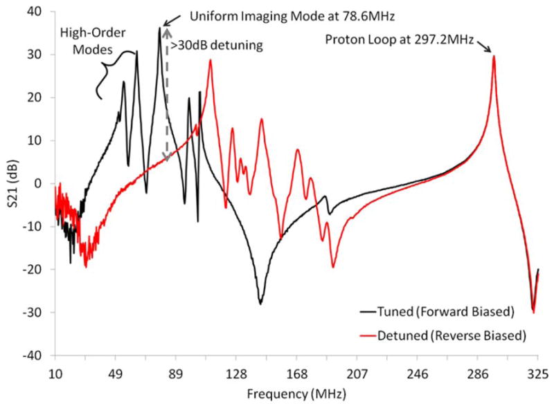
Spectra of the tuned (forward biased PIN diodes, black line) and detuned (reverse biased PIN diodes, red line) sodium birdcage along with a proton coil. Diode detuning provided greater than 30 dB of isolation at 78.6 MHz (gray arrow). The proton coil showed insignificant interaction with the tuned and detuned sodium birdcage at the proton resonance frequency 297.2 MHz.
Table 2.
Q measurements for elements of the developed dual-nuclei array.
| Coil | Environment | Qunloaded | Qloaded | Coil Noise (%) |
|---|---|---|---|---|
| Sodium receive coil | 1 | 330 | 105 | 17 |
| Sodium receive coil | 2 | 260 | 85 | 18 |
| Sodium receive coil | 3 | 190 | 70 | 21 |
| Sodium receive coil | 4 | 180 | 70 | 22 |
| Sodium birdcage | 1* | 220 | 40 | 10 |
| Sodium birdcage | 1 | 130 | 50 | 22 |
| Sodium birdcage | 4 | 110 | 55 | 29 |
| Proton coil | 1 | 210 | 140 | 42 |
| Proton coil | 4 | 205 | 155 | 51 |
All Q measurements were made after minor capacitive adjustments (less than 10% for the sodium birdcage, and less than 5% for the sodium array and proton array) to compensate for shielding during integration of the three modules such that all sodium coils were tuned to 78.6 MHz and proton coils were tuned to 297.2 MHz.
indicates that measurements were made before detuning diodes and RF chokes were added to the birdcage.
Sodium coil Q measurements (Table 2) show that the percentage of coil noise associated with a single coil in isolation was 17% and increased to 22% in situ with the complete sodium receive array, detunable sodium birdcage, proton array, and associated electronics. This increase in noise and corresponding reduction in sodium coil Q could likely be attributed to copper losses caused by shielding and the associated induced currents in the surrounding detuned birdcage and, to a lesser extent, neighboring proton coils. S21 measurements with a double decoupled probe showed that sodium receive coil sensitivity was reduced by more than 40 dB by active diode detuning. Active detuning resulted in split resonances at 60.5 MHz and 105.0 MHz which were well out of range of the frequencies of interest at 78.6 MHz and 297.2 MHz. Neighboring coils were coupled by less than −14 dB and next-nearest neighbors were coupled by less than −8 dB when loaded by the phantom. Preamplifier decoupling provided more than 25 dB of isolation.
SNR maps in Figure 4 show that the developed dual-nuclei sodium array provided approximately 10% SNR gain in the center of the phantom over the commercial mono-nuclear sodium birdcage and approximately 2.3-fold gain in the phantom periphery using optimal SNR reconstruction. Conventional sum-of-squares SNR reconstruction resulted in similar gains at the center and approximately 1.8-fold gain in the phantom periphery. Notably, the proton array had a negligible effect on sodium SNR. The SNR of the nine central voxels in transverse images was 11.3 ± 1.0 (mean ± standard deviation) for the dual-nuclei sodium array before the proton array was added, 11.5 ± 0.6 for the dual-nuclei sodium array in the presence of the proton array, 10.2 ± 1.0 for the mono-nuclear sodium birdcage, and 7.6 ± 0.7 for the detunable sodium birdcage. As a secondary note, the mono-nuclear birdcage SNR was 34% greater than the detunable sodium birdcage in transmit-receive mode, again due to efficiency-degrading factors mentioned above. Although the eight-channel sodium array is the primary means for reception, receive capability is also available on the detunable sodium birdcage to provide a uniform image useful for sodium quantification. SNR profiles through the transverse and sagittal SNR maps also demonstrate the improved performance of the sodium array, particularly in the phantom periphery (Figure 5a). The SNR profiles in the head-foot direction indicate that the sodium array and mono-nuclear sodium birdcage provide similar coverage (Figure 5b). In vivo sodium SNR maps similarly show that the developed array provided gains of 1.2 to 1.7-fold in the articular cartilage over the mono-nuclear birdcage (Figure 6) (this advantage was 1.1 to 1.4-fold with sum-of-squares reconstruction). Increased background levels in the dual-nuclei array SNR maps is a reconstruction artifact which increases with channel count due to the absence of accurate coil sensitivity calibration in these regions. A comparison of 3D radial acquisitions using the dual-nuclei and mono-nuclear coils on the same subject are shown in Figure 7. Although it is not straightforward to calculate the SNR of a radial acquisition, the sensitivity of the developed dual-nuclei coil is clearly superior to that of the mono-nuclear volume coil, particularly in the patellar and femoro-tibial cartilage.
Figure 4.
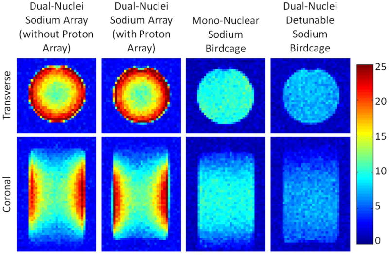
Sodium phantom SNR maps with optimal SNR combination. The dual-nuclei sodium array provided 2.3-fold SNR improvement in the phantom periphery and 10% SNR improvement in the phantom center over the mono-nuclear sodium birdcage.
Figure 5.
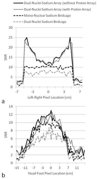
SNR profiles across the center of the SNR maps in Figure 4. Profiles in (a) were taken from transverse maps and those in (b) were taken from coronal maps.
Figure 6.
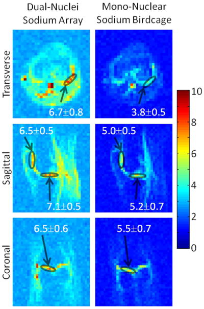
In vivo sodium SNR maps in the same subject with optimal SNR combination. Values superimposed on maps indicate mean ± standard deviation SNR in selected regions-of-interest (circles) in the articular cartilage.
Figure 7.

In vivo sodium images using 3D radial acquisitions, co-registered between the dual-nuclei array (left) and the mono-nuclear sodium birdcage (right).
Proton MRI
Neighboring proton coils were coupled by −9.4 to −11.9 dB and next nearest neighbors were coupled by −11.8 to −13.0 dB while the array was loaded with the phantom. Preamplifier decoupling provided greater than 14 dB isolation. The transmit power required for 90° excitation in the center of the knee with a 1 ms hard pulse for the dual-nuclei array and mono-nuclear birdcage was 365 W and 180 W, respectively (equivalently, a 90° excitation was achieved with a 1 kW hard pulse applied for 0.60 ms and 0.42 ms, respectively). The relatively low transmit efficiency of the proton array in the dual-nuclei coil can be attributed to the very sparse arrangement of small transmitter loops that was selected to achieve adequate decoupling. The weak coupling of these small loops to the body is reflected in the relatively low unloaded to loaded Q ratio (Table 2).
In vivo proton SNR maps (Figure 8) and profiles (Figure 9) show that the dual-nuclei proton coil achieved lower SNR in the center compared to the mono-nuclear proton birdcage, but higher SNR in the periphery. (Optimal reconstruction was utilized for the dual-nuclei proton data in Figures 8 and 9; sum-of-squares reconstruction resulted in less than 6% SNR loss. Sum-of-squares and optimal SNR reconstructed values were within 1% for the mono-nuclear proton birdcage.) It should be noted that proton transmit calibration was performed in the center of the knee. Other locations are biased by underlying B1+ variation. The coverage of the developed coil in the head-foot direction was less than that of mono-nuclear birdcage but was adequate for the purposes of B0 shimming and obtaining anatomical reference images. The FWHM coverage was approximately 8.9 cm and 11.9 cm for the dual-nuclei proton array and mono-nuclear birdcage, respectively. The dual-nuclei proton array provided good coverage in the transverse plane despite its sparse geometry. The off-resonance of all voxels in the three-plane B0 maps inside the shim volume (voxels outside the shim volume or in the background air were removed) was 64.0 ± 131.7 Hz with the default system shim settings and 32.6 ± 82.2 Hz after B0 shimming.
Figure 8.
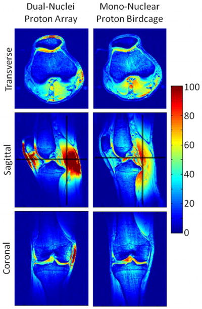
In vivo proton SNR maps using optimal SNR combination obtained with the dual-nuclei array (left) and the mono-nuclear proton birdcage (right) in the same subject. Black lines in the sagittal SNR maps indicate locations of the SNR profiles in Figure 9.
Figure 9.
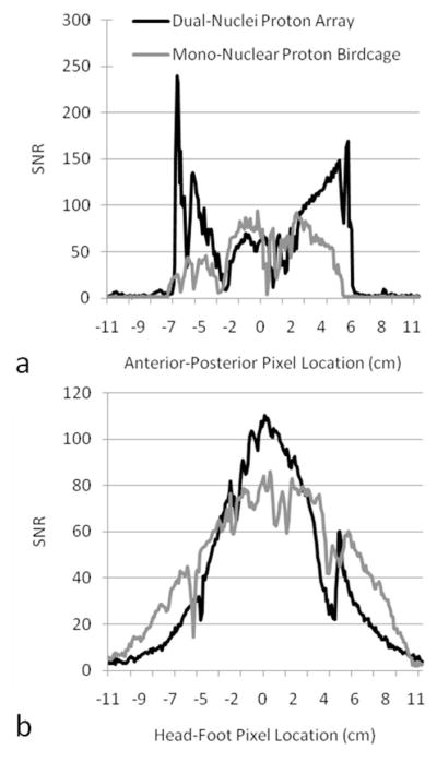
In vivo proton SNR profiles through sagittal SNR maps along the lines indicated in Figure 8.
DISCUSSION
This study demonstrates that a dual-nuclei multiple-channel array can provide substantial sodium channel SNR gain over a conventional mono-nuclear sodium birdcage. By judiciously managing the resonances of each component of the array, the sodium receive channels were maintained in the most favorable form, without SNR-lowering circuitry that is commonly used in dual-tuned coils such as trap circuits or in-line PIN diodes. The proposed approach resulted in sodium SNR gains of 1.2 to 1.7 fold in vivo and additionally provided proton B0 shimming and co-registered anatomical reference imaging capabilities. The performance of the sodium receive coils in the presence of the sodium birdcage and proton coils was of particular interest given the low baseline SNR of sodium MRI. Q measurements showed that the sodium receive coils were not substantially affected by the detuned sodium birdcage or proton coils. The proton coils are not conducive to coupling at the sodium frequency due to their relatively high-impedance (the total series capacitance and inductance of the proton coils was approximately 2.3 pF and 123 nH, respectively, which translates into a series impedance of −j808.3 Ω at 78.6MHz) and short perimeter (20 cm, or 19 times shorter than one wavelength at 78.6 MHz).
Initial experiences with a double birdcage system where a proton birdcage was placed coaxially within a sodium birdcage similar to that described in (18) indicated that the sodium birdcage caused a high degree of shielding and disturbance to the proton birdcage. This led to difficulty in achieving the desired sinusoidal current distribution and quadrature port isolation. This problem was avoided in the coil presented here through the use of small coils for the proton channel whose interaction with the sodium receive coils and sodium birdcage was inconsequential. Further, because the proton and sodium receive coils shared the same former, shielding of the proton coils was reduced, allowing both coils to tightly encircle the knee. The proton coils would be undesirably shielded from the sample if they were placed outside the sodium coils, while lower sodium SNR would result if the proton coils were placed inside the sodium coils (given the space limitation set by the selected inner former diameter). One potential disadvantage of the proton array approach is the non-uniform B1+ field associated with a sparse array of surface coil transmitters, where peripheral excitation can be stronger than that at depth. However, birdcage coils of similar diameter also suffer from inhomogeneous B1+ at 7 T, where RF interference typically results in central brightening and weak peripheral excitation.
In summary, a novel dual-frequency sodium/proton coil was developed for knee imaging at 7 T. The wide sodium/proton spectral separation allowed the implementation of distinct coils for each nuclei, resulting in improved SNR and a departure from traditional dual-tuned coils. The developed coil represents an advance in sodium MRI as operation at 7 T provides a fundamental SNR advantage over lower field strengths, while the eight-channel sodium receive array further improves SNR over a conventional birdcage. The sodium receive array also facilitates parallel imaging (30–31) and allows the complementary application of compressed sensing (32–33) which may be a powerful combination for sodium radial acquisitions (34).
Acknowledgments
The authors thank Cornel Stefanescu for construction of the coil housing and Pippa Storey for pulse sequence assistance.
NIH grant support: R01 AR056260, R01 AR060238, and R01 EB002568
References
- 1.Reddy R, Insko EK, Noyszewski EA, Dandora R, Kneeland JB, Leigh JS. Sodium MRI of human articular cartilage in vivo. Magn Reson Med. 1998;39(5):697–701. doi: 10.1002/mrm.1910390505. [DOI] [PubMed] [Google Scholar]
- 2.Shapiro EM, Borthakur A, Gougoutas A, Reddy R. 23Na MRI accurately measures fixed charge density in articular cartilage. Magn Reson Med. 2002;47(2):284–291. doi: 10.1002/mrm.10054. [DOI] [PMC free article] [PubMed] [Google Scholar]
- 3.Wang L, Wu Y, Chang G, Oesingmann N, Schweitzer ME, Jerschow A, Regatte RR. Rapid isotropic 3D-sodium MRI of the knee joint in vivo at 7T. J Magn Reson Imaging. 2009;30(3):606–614. doi: 10.1002/jmri.21881. [DOI] [PMC free article] [PubMed] [Google Scholar]
- 4.Madelin G, Lee JS, Inati S, Jerschow A, Regatte RR. Sodium inversion recovery MRI of the knee joint in vivo at 7T. J Magn Reson. 2010;207(1):42–52. doi: 10.1016/j.jmr.2010.08.003. [DOI] [PMC free article] [PubMed] [Google Scholar]
- 5.Lesperance LM, Gray ML, Burstein D. Determination of fixed charge density in cartilage using nuclear magnetic resonance. J Orthop Res. 1992;10(1):1–13. doi: 10.1002/jor.1100100102. [DOI] [PubMed] [Google Scholar]
- 6.Borthakur A, Shapiro EM, Beers J, Kudchodkar S, Kneeland JB, Reddy R. Sensitivity of MRI to proteoglycan depletion in cartilage: comparison of sodium and proton MRI. Osteoarthritis Cartilage. 2000;8(4):288–293. doi: 10.1053/joca.1999.0303. [DOI] [PubMed] [Google Scholar]
- 7.Borthakur A, Mellon E, Niyogi S, Witschey W, Kneeland JB, Reddy R. Sodium and T1rho MRI for molecular and diagnostic imaging of articular cartilage. NMR Biomed. 2006;19(7):781–821. doi: 10.1002/nbm.1102. [DOI] [PMC free article] [PubMed] [Google Scholar]
- 8.Trattnig S, Friedrich K, Bogner W, Welsch G. Advanced musculoskeletal MRI at ultra-high field (7T) Imaging in Medicine. 2010;2:99–114. [Google Scholar]
- 9.Staroswiecki E, Bangerter NK, Gurney PT, Grafendorfer T, Gold GE, Hargreaves BA. In vivo sodium imaging of human patellar cartilage with a 3D cones sequence at 3 T and 7 T. J Magn Reson Imaging. 2010;32(2):446–451. doi: 10.1002/jmri.22191. [DOI] [PMC free article] [PubMed] [Google Scholar]
- 10.Schnall MD, Subramanian VH, Leigh JS, Chance B. A new double-tuned probe for concurrent 1H and 31P NMR. J Magn Reson. 1985;65:122–129. [Google Scholar]
- 11.Shen GX, Boada FE, Thulborn KR. Dual-frequency, dual-quadrature, birdcage RF coil design with identical B1 pattern for sodium and proton imaging of the human brain at 1. 5 T. Magn Reson Med. 1997;38(5):717–725. doi: 10.1002/mrm.1910380507. [DOI] [PubMed] [Google Scholar]
- 12.Matson GB, Vermathen P, Hill TC. A practical double-tuned 1H/31P quadrature birdcage headcoil optimized for 31P operation. Magn Reson Med. 1999;42(1):173–182. doi: 10.1002/(sici)1522-2594(199907)42:1<173::aid-mrm23>3.0.co;2-o. [DOI] [PubMed] [Google Scholar]
- 13.Isaac G, Schnall MD, Lenkinski RE, Vogele K. A design for a double-tuned birdcage coil for use in an integrated MRI/MRS examination. J Magn Reson. 1990;89:41–50. [Google Scholar]
- 14.Vaughan JT, Hetherington HP, Otu JO, Pan JW, Pohost GM. High frequency volume coils for clinical NMR imaging and spectroscopy. Magn Reson Med. 1994;32(2):206–218. doi: 10.1002/mrm.1910320209. [DOI] [PubMed] [Google Scholar]
- 15.Xie Z, Xu D, Kelley DA, Vigneron DB, Zhang X. ISMRM Workshop on Advances in High Field MR. Pacific Grove; California, USA: 2007. Dual-frequency Volume Microstrip Coil with Quadrature Capability for 13C/1H MRI/MRS at 7T; p. Poster 41. [Google Scholar]
- 16.Ha S, Hamamura MJ, Nalcioglu O, Muftuler LT. A PIN diode controlled dual-tuned MRI RF coil and phased array for multi nuclear imaging. Phys Med Biol. 2010;55(9):2589–2600. doi: 10.1088/0031-9155/55/9/011. [DOI] [PubMed] [Google Scholar]
- 17.Murphy-Boesch J, Srinivasan R, Carvajal L, Brown TR. Two configurations of the four-ring birdcage coil for 1H imaging and 1H-decoupled 31P spectroscopy of the human head. J Magn Reson B. 1994;103(2):103–114. doi: 10.1006/jmrb.1994.1017. [DOI] [PubMed] [Google Scholar]
- 18.Fitzsimmons JR, Beck BL, Brooker HR. Double resonant quadrature birdcage. Magn Reson Med. 1993;30(1):107–114. doi: 10.1002/mrm.1910300116. [DOI] [PubMed] [Google Scholar]
- 19.Webb AG, Smith NB, Aussenhofer S, Kan HE. Use of Tailored Higher Modes of a Birdcage to Design a Simple Double-Tuned Proton/Phosphorus Coil for Human Calf Muscle Studies at 7 T. Concepts in Magn Reson Part B. 2011;39B(2):89–97. [Google Scholar]
- 20.Wiggins GC, Brown R, Fleysher L, Zhang B, Stoeckel B, Inglese M, Sodickson DK. ISMRM. Stockholm; Sweden: 2010. A Nested Dual Frequency Birdcage/Stripline Coil for Sodium/Proton Brain Imaging at 7T; p. 1500. [Google Scholar]
- 21.Roemer PB, Edelstein WA, Hayes CE, Souza SP, Mueller OM. The NMR phased array. Magn Reson Med. 1990;16(2):192–225. doi: 10.1002/mrm.1910160203. [DOI] [PubMed] [Google Scholar]
- 22.Wiggins GC, Polimeni JR, Potthast A, Schmitt M, Alagappan V, Wald LL. 96-Channel receive-only head coil for 3 Tesla: design optimization and evaluation. Magn Reson Med. 2009;62(3):754–762. doi: 10.1002/mrm.22028. [DOI] [PMC free article] [PubMed] [Google Scholar]
- 23.Hayes CE, Axel L. Noise performance of surface coils for magnetic resonance imaging at 1. 5 T. Med Phys. 1985;12(5):604–607. doi: 10.1118/1.595682. [DOI] [PubMed] [Google Scholar]
- 24.Lattanzi R, Sodickson DK. Ideal current patterns yielding optimal signal-to-noise ratio and specific absorption rate in magnetic resonance imaging: Computational methods and physical insights. Magn Reson Med. 2011 doi: 10.1002/mrm.23198. Published in early view. [DOI] [PMC free article] [PubMed] [Google Scholar]
- 25.Schnell W, Renz W, Vester M, Ermert H. Ultimate Signal-to-Noise-Ratio of Surface and Body Antennas for Magnetic Resonance Imaging. IEEE T Antennas and Propagation. 2000;48(3):418–428. [Google Scholar]
- 26.Gabriel S, Lau RW, Gabriel C. The dielectric properties of biological tissues: III. Parametric models for the dielectric spectrum of tissues. Phys Med Biol. 1996;41(11):2271–2293. doi: 10.1088/0031-9155/41/11/003. [DOI] [PubMed] [Google Scholar]
- 27.Kellman P, McVeigh ER. Image reconstruction in SNR units: a general method for SNR measurement. Magn Reson Med. 2005;54(6):1439–1447. doi: 10.1002/mrm.20713. [DOI] [PMC free article] [PubMed] [Google Scholar]
- 28.Breton E, McGorty K, Wiggins GC, Axel L, Kim D. Image-guided radio-frequency gain calibration for high-field MRI. NMR Biomed. 2010;23(4):368–374. doi: 10.1002/nbm.1471. [DOI] [PMC free article] [PubMed] [Google Scholar]
- 29.Reeder SB, Wen Z, Yu H, Pineda AR, Gold GE, Markl M, Pelc NJ. Multicoil Dixon chemical species separation with an iterative least-squares estimation method. Magn Reson Med. 2004;51(1):35–45. doi: 10.1002/mrm.10675. [DOI] [PubMed] [Google Scholar]
- 30.Pruessmann KP, Weiger M, Scheidegger MB, Boesiger P. SENSE: sensitivity encoding for fast MRI. Magn Reson Med. 1999;42(5):952–962. [PubMed] [Google Scholar]
- 31.Sodickson DK, Manning WJ. Simultaneous acquisition of spatial harmonics (SMASH): ultra-fast imaging with radiofrequency coil arrays. Magn Res Med. 1997;38:591–603. doi: 10.1002/mrm.1910380414. [DOI] [PubMed] [Google Scholar]
- 32.Otazo R, Kim D, Axel L, Sodickson DK. Combination of compressed sensing and parallel imaging for highly accelerated first-pass cardiac perfusion MRI. Magn Reson Med. 2010;64(3):767–776. doi: 10.1002/mrm.22463. [DOI] [PMC free article] [PubMed] [Google Scholar]
- 33.Lustig M, Donoho D, Pauly JM. Sparse MRI: The application of compressed sensing for rapid MR imaging. Magn Reson Med. 2007;58(6):1182–1195. doi: 10.1002/mrm.21391. [DOI] [PubMed] [Google Scholar]
- 34.Madelin G, Chang G, Otazo R, Jerschow A, Regatte RR. Compressed Sensing Sodium MRI of Cartilage at 7T: Preliminary Study. J Magn Reson. doi: 10.1016/j.jmr.2011.12.005. in press. [DOI] [PMC free article] [PubMed] [Google Scholar]