Abstract
After the rapid growth in the use of CoCrMo metal-on-metal hip replacements since the second generation was introduced circa 1990, metal-on-metal hip replacements have experienced a sharp decline in the last two years due to biocompatibility issues related to wear and corrosion products. Despite some excellent clinical results, the release of wear and corrosion debris and the adverse response of local tissues have been of great concern. There are many unknowns regarding how CoCrMo metal bearings interact with the human body. This perspective article is intended to outline some recent progresses in understanding wear and corrosion of metal-on-metal hip replacement both in-vivo and in-vitro. The materials, mechanical deformation, corrosion, wear-assisted corrosion, and wear products will be discussed. Possible adverse health effects caused by wear products will be briefly addressed, as well as some of the many open questions such as the detailed chemistry of corrosion, tribochemical reactions and the formation of graphitic layers. Nowadays we design almost routinely for high performance materials and lubricants for automobiles; humans are at least as important. It is worth remembering that a hip implant is often the difference between walking and leading a relatively normal life, and a wheelchair.
1 Background
Prosthetic implantation is one of the most successful treatments for patients with severe arthritis or rheumatism. As of 2003, more than 200,000 total hip replacement operations were performed annually in the US, and this number is expected to reach 572,000 by 2030 1. The bearing surfaces of current artificial hip replacements on the market are usually made out of ultra-high-molecular-weight polyethylene (UHMWPE), cobalt-chromium-molybdenum (CoCrMo) alloys, ceramics (alumina) or ceramicized metals (e.g. oxygen diffusion-hardened ZrNb alloys). Of these types of devices, metal-on-polyethylene (MoP) prevails in the primary total hip replacement market, which consists of a CoCrMo femoral ball and a UHMWPE cup. MoP has shown overall good clinical results with relatively low wear rate and long term survivorship. However, MoP device generates polyethylene wear particles which have been proven to cause osteolysis, i.e. periprosthetic bone loss 2. When a hip replacement fails, due to subsequent loosening, revision surgery may need to be performed, which causes substantial morbidity risk for the patient and, on a population basis, imposing a large burden on the health care system.
In the 1990s with the introduction of a second generation of devices, metal-on-metal (MoM) bearings have attracted great interest as an alternative to MoP because of their excellent mechanical properties and corrosion resistance 3. Some MoM devices have functioned well in-vivo for more than twenty years 4, and the wear rate in-vivo was only several microns per year, a number much lower than MoP 5–7. About 35% of the hip replacements in the US were MoM bearings at the height of their popularity in the mid 2000’s 8. MoM hip implants, however, are not immune to wear debris and biocompatibility issues. The wear debris generated by MoM devices ranges from particles tens of nanometers to submicron in size. Thus, despite a low wear rate, the number of wear particles is substantial. Mounting evidence has shown that wear debris and metal ions disseminate to both the surrounding tissue and bone as well as remote locations in the body, potentially causing adverse health effects 9, 10. During revision surgeries or postmortem examination, discolored tissue is frequently observed around CoCrMo implants; some patients feel unexplained pain that may be associated with the tissue damage caused by MoM hip replacement wear. Concerned with the possible adverse health effects of wear particles, the regulatory agencies of the UK (MHRA) and US (FDA) issued alerts for all MoM hip replacement in 2010 and 2011, respectively. The use of MoM for primary hip replacement surgery has dropped remarkably since then, although there remain a large number of people who still have these implants in situ. In most cases, these implants are still functioning well. Because these devices have the potential to be an effective and durable treatment for end stage arthritis of the hip, and because there are currently a large number of patients with these devices in situ, a better understanding of how the metallic nanoparticles are generated and their influence is important.
The wear process of material removal at the sliding interface of MoM hip replacements has been investigated extensively through in-vivo and in-vitro simulator tests. Due to the complex nature of materials degradation processes involving simultaneous mechanical and chemical reactions, how the materials are released from the articulating surface to the human body is still not fully clear. A few models 11 have been developed to elucidate wear and corrosion processes in the biological environment, most of which are at the submicron to millimeter scale as against atomistic and are based on classic contact mechanics. The interplay of mechanical and chemical reactions makes this a truly multidisciplinary problem that needs investigation beyond the traditional boundaries; for instance, the metallurgy of the implant couples with the biochemical processes taking place within the patient to produce ion to nanometer size wear debris.
With the emergence of state-of-the-art testing and characterization techniques, the study of wear and wear products at the nanometer scale has made great progress over the past decade. These techniques provide new insights into the wear process that take place in the material within hundreds of nanometers of the surface. The aim of this perspective is to address recent progress in the understanding of the tribological behaviors of MoM hip replacements both in-vitro and in-vivo, particularly improvements in our understanding of nanoscale wear. The materials, wear, corrosion, debris, and their possible adverse health effects will be discussed, as well as some of the many open questions which merit further study.
2 Materials
CoCrMo alloys are used for medical implants owing to their excellent wear and corrosion resistance. The CoCrMo alloys are composed of 58.9–69.5% Co, 27.0–30% Cr, 5.0–7.0% Mo, and small amount of other elements (Mn, Si, Ni, Fe and C), complying with the ASTM standards of F-75 or F-1537 for cast alloys and wrought alloys, respectively. The CoCrMo matrix is an hcp phase at equilibrium. Due to the sluggish phase transformation, the matrix of both the as-cast and wrought states is mostly the meta-stable fcc phase 12. Based on their carbon contents, CoCrMo alloys are grouped into two categories, i.e. high-carbon alloy with 0.05–0.35 wt.% carbon, and low-carbon alloys with carbon concentration < 0.05 wt.%. A number of carbide hard phases are present in high-carbon alloys 13. It is generally agreed that high-carbide alloys are superior to the low-carbon ones in terms of wear-resistance owing to the strengthening effects of the carbides 14. For instance, low carbon bearings are subject to a higher wear rate in the ‘bedding-in’ stage, whilst the difference between high carbon and low-carbon alloys is insignificant during the steady wear stage 15.
Although the metallurgy for CoCrMo alloys with carbon has been studied for a long time, there is no complete phase diagram, partly due to the complex phases present in this system. Different carbide species, such as M23C6, and M6C can be formed depending on the heat treatment history 13. In general, the wrought alloy has uniform, small grains of few microns in size and ~1 μm large carbide precipitates throughout the matrix. Select area electron diffraction and energy dispersive spectrum (EDS) results showed that the carbides are composed of single phase M23C6 structure, with a chemical composition of Co14Cr72Mo14 (in wt.%) 16. Cast alloys, on the other hand, contain blocky ‘carbides’ of ~50 μm in size. It was reported 13 that solution-annealed cast alloy at 1230 °C for 0.25 hour results in a transition from interdendritic M23C6 carbides to M6C carbides. With longer time annealing at 1225 °C for 24–48 hr, the M23C6 carbides may completely dissolve into the matrix 17.
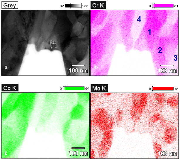
In a recent study 16, it was shown that the blocky ‘carbide’ in as-cast alloys is a mixture of a large number of fine phases as opposed to a single phase. Figure 1a shows a transmission electron microscope (TEM) bright-field micrograph of the carbide prepared using focused ion beam (FIB). The chemical compositions of the nano-phases are either chromium rich or cobalt/molybdenum rich; see Table 1. Electron diffraction showed that these grains are a mix of M23C6 structure, fcc phase, and Co9Mo15 σ phase 18.
Figure 1.
(a) Bright-field TEM micrograph of a blocky ‘carbide’ consisting of mixed fine structures. The elements are mapped in (b) for Cr, (c) for Co and (d) for Mo using EDS in a TEM. The chemical composition of regions 1–4 are listed in Table 1. (from 16)
Table 1.
Chemical composition of the four regions marked in Figure 1. The standard deviation is listed in the brackets. (from 16)
| Wt.% | Cr | Co | Mo |
|---|---|---|---|
| 1 | 57.14 (0.54) | 28.62 (0.48) | 14.24 (0.77) |
| 2 | 62.57 (0.59) | 30.53 (0.53) | 6.90 (0.59) |
| 3 | 22.11 (0.38) | 75.05 (0.79) | 2.85 (0.45) |
| 4 | 22.27 (0.54) | 43.74 (0.85) | 33.99 (1.65) |
The origin of the mixed hard phases was studied through cooling rate experiments, in which wrought alloy specimens were remelted and subsequently cooled to room temperature at different cooling rates 16. For the specimens cooled at 50 °C/s, single-phase carbides identical to the carbide in wrought alloy were formed. In comparison, slow cooling rate of 0.2 °C/s generated the mixed hard phases. It is postulated that the mixed hard phases are more thermal-dynamically stable, and that the meta-stable single phase M23C6 carbide is kinetically favorable during fast cooling from the melt.
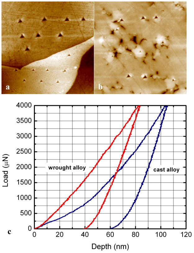
Carbides are generally strength enhancers due to their remarkable hardness. Figure 2 shows nanoindentation results for the mixed hard phases and single phase carbide. The nanohardness of the mixed hard phases is ~13 GPa, whilst the single phase M23C6 carbide is twice as hard (~28 GPa). While the single phase carbides in wrought alloys usually exhibit little sign of fracture, cracks have been frequently observed within the mixed hard phases in retrieved hip replacements 16. The variations in the carbide microstructure, chemical composition, and nanohardness are directly associated with the wear performance.
Figure 2.
AFM micrographs (20 μm × 20 μm) of carbides in (a) cast alloy and (b) wrought alloy after nanoindentation tests. The corresponding force-displacement curves are showed in (c). Less plastic deformation was produced in the wrought alloy carbide. (from 16)
3 Nanoscale Wear
Wear of hip replacements is a multifactorial process involving the materials’ intrinsic properties such as yield strength, hardness, ductility, fracture toughness, as well as the extrinsic properties, such as load and environment. Smith, Dowson and Goldsmith found that in the presence of pseudo synovial fluid the lubrication of metal hip replacements is sensitive to femoral head size 19. Bearings of 28 mm diameter or less operate in boundary lubrication or mixed film lubrication regime19–21. With increasing femoral size to 36 mm, the lubrication can shift towards full fluid film lubrication regime where surface separate can take place during a walking cycle 19, 20, 22. The average pressure for a hip replacement in-vivo is ~50 MPa 11, which is smaller than the yield strength. The wear processes in-vivo are difficult to evaluate, and are influenced by the activity level of patients. Many tests have been performed using in-vitro hip simulators to mimic the wear process in the human body, which agree well with in-vivo results 23–25.
Retrieved hip replacements as well as specimens after in-vitro tests are commonly subject to surface morphology measurements in order to probe the deformation mechanisms. Cross-section TEM examination has been employed to analyze the plastic deformation in the articulating surface. It is frequently observed that a layer of nanocrystalline material with grains tens of nanometer in size is formed underneath the contacting surface after sliding 26. Büscher and Fischer 27 examined the cross-section surface of retrieved low-carbon CoCrMo hip replacement, as well as pin-on-disc test with a maximum Hertzian contact pressure of ~370 MPa. Figure 3 shows a TEM bright-field micrograph of the surface, in which fine granular crystals of ~50 nm in size are present in the materials within ~1 μm from the surface. For comparison, the grain size of intact materials is ~600 μm for as-cast alloy and 37 μm for forged alloys. The surface of materials subject to heavy plastic deformation induced by shear stresses can be dynamically recrystallized leading to ultra-fine grains or nanocrystals 27. The authors suggested that the nanograins may rotate during sliding, a process referred to as ‘mechanical mixing’, and bring carbon on the surface into the surface materials, which can be detected using electron energy loss spectroscopy (EELS). Dislocation cross-slip, on the other hand, is suppressed due to the low stacking fault energy of the fcc matrix. It is worth noting that similar nano-grains can also be generated in alumina ceramic hip replacement 28. It is still unclear exactly how the nano-grains are produced or rotate under shear stresses. Recent progresses on imaging and nano-manipulation in a TEM has made direct observation possible. While the tribology problems are observable in traditional investigation at the macroscopic scale, the fundamental wear mechanisms of slicing single asperity at the nano-meter scale remains to be understood. Materials behave very differently when the size shrinks to the nanoscale. For instance, gold appears to deform almost like a liquid 29 which has been suggested is due to the high surface diffusion rate.
Figure 3.
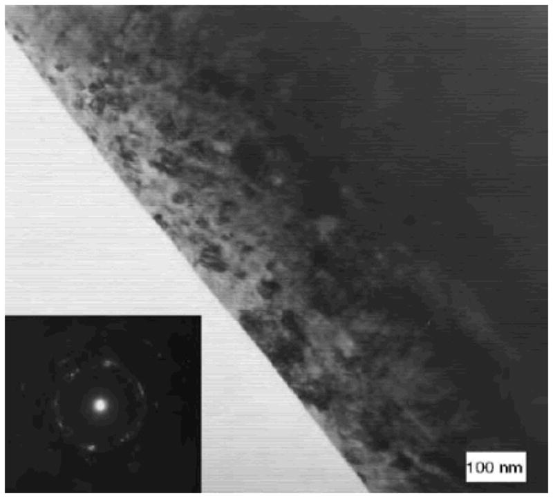
Nanocrystallites are formed at the surface of retrieved CoCrMo hip replacement. (from27)
In addition to elastic / plastic deformation, it is interesting that sliding of counter surfaces can also stimulate mechano-chemical reactions. A few fundamental studies have shown that chemical states of the sliding surface are altered. For instance, carbon will undergo an sp3-to-sp2 transition under sliding conditions 30. Merkle et al. examined the EELS spectrum of near frictionless carbon film during in-situ sliding in TEM, and found increased sp2 carbon after 250 passes. Pastewka et al. 31 reported sp3-to-sp2 transition in diamond grinding. Based on their molecular dynamics simulations, dry sliding of diamond counterparts dissociates the carbon sp3 crystal bond leading to disordered sp2 bonds, creating an amorphous carbon layer on the surface. The amorphous layer is subsequently removed mechanically due to its lower hardness, or etched away by ambient oxygen or perhaps water (the water-gas shift reaction). Li et al. 32 compared sliding of silica AFM tip on different substrates, and observed time-dependent friction strength for silica-silica contacts, which is caused by forming hydrogen or siloxane bonds.
While mechano-chemical reactions have not been reported for MoM hip replacements, wear induced chemical reaction between the metal and protein-rich biological fluid would not be surprising. In simulation tests, the proteins in the media significantly reduce the friction, as the sliding in serum has lower friction coefficient compared to NaCl aqueous solution. Proteins carry negative net charge and can be absorbed to the metal surfaces serving as solid lubricants 33. In addition, a layer tribological film is widely observed to be formed on CoCrMo and other metal surfaces 34. A detailed understanding of the reaction pathways, activation energies and other aspects of the physical chemistry taking place is an area of MoM implant research where much work could be done.
4. Tribocorrosion
Examination of hip replacements after in-vitro and in-vivo use showed a notable degree of corrosion for CoCrMo and titanium alloys at both articulating surface and the taper at the neck of modular total hip replacement 35–37. Metallic materials can be removed from the surface in the form of metal ions or oxides via chemical and electrochemical reactions in corrosive environment. In general, metals are oxidized to their salt through anodic reactions, i.e.M → Mn+ + ne− driven by thermodynamic forces to lower the free energy. In order for corrosion to occur, the electrons need to be consumed by cathodic reactions with hydrogen, oxygen and water. At thermodynamic equilibrium, the rate of metal oxidation is balanced by cathodic reactions. As a result, metal ions with positive charges are released into solution, while the electrons are left inside the metal, forming an electric double layer with a potential difference across the metal surface. This potential is a characteristic property associated only with the material. The potentials of some metals and compounds related to CoCrMo hip replacement are listed in Table 2; the metals with more negative potential are more reactive to corrosion. As evident from the table, the potentials of Co, Cr, Ti, and Fe are negative, indicating they are all reactive in aqueous solutions even in absence of an applied potential.
Table 2.
Electrochemical series for selected metals and compounds 93.
| Reaction | Potential (V) | ||
|---|---|---|---|
| Au3+ + 3e− | ↔ | Au | 1.498 |
| Ag+ + e− | ↔ | Ag | 0.7996 |
| SiO2 + 4H+ + 4e− | ↔ | Si + 2H2O | 0.857 |
| O2 + 2H2O +4e− | ↔ | 4 OH− | 0.401 |
| 2H+ + 2e− | ↔ | H2 | 0.0000 |
| 2H2O + 2e− | ↔ | H2 + 2OH− | −0.8277 |
| Ti(OH)3+ + H+ + e− | ↔ | Ti3+ +H2O | −0.055 |
| Ti2+ + 2e− | ↔ | Ti | −1.630 |
| TiO2 + 4H+ +2e− | ↔ | Ti2+ + 2H2O | −1.789 |
| Fe2+ + 2e− | ↔ | Fe | −0.447 |
| Fe3+ + 3e− | ↔ | Fe | −0.037 |
| Cr2+ + 2e− | ↔ | Cr | −0.913 |
| Cr3+ + 3e− | ↔ | Cr | −0.744 |
| Cr(OH)3 + 3e− | ↔ | Cr + 3OH− | −1.48 |
| Co2+ + 2e− | ↔ | Co | −0.28 |
| Co(OH)2 + 2e− | ↔ | Co + 2OH− | −0.73 |
| Mo3+ + 3e− | ↔ | Mo | −0.200 |
| MoO2 + 4H+ + 4e− | ↔ | Mo + 4H2O | −0.152 |
| MoO3 + 6H+ + 6e− | ↔ | Mo + 3H2O | −0.075 |
| Al3+ + 3e− | ↔ | Al | −1.662 |
| Ca2+ + 2e− | ↔ | Ca | −2.868 |
| Mg2+ + 2e− | ↔ | Mg | −2.372 |
Due to the high reactivity, Co and Cr are oxidized rapidly at the surface, forming an oxide layer, such as Cr2O338, 39. The oxide layer physically blocks the contact between the solution and metal, a process known as passivation, which reduces corrosion. The orthopedic metals are artificially over-passivated with an electric bias; this builds up a protective oxide film before implantation to prevent severe corrosion. During service, the passive film can be removed by abrasion or fracture in fretting wear, exposing unoxidized metal to the solution. New passive film can be reformed during corrosion and serve as a barrier to further corrosion. The passivation and repassivation processes play an essential role in improving the lifetime of hip replacement, as passivation is necessary to improve corrosion resistance.
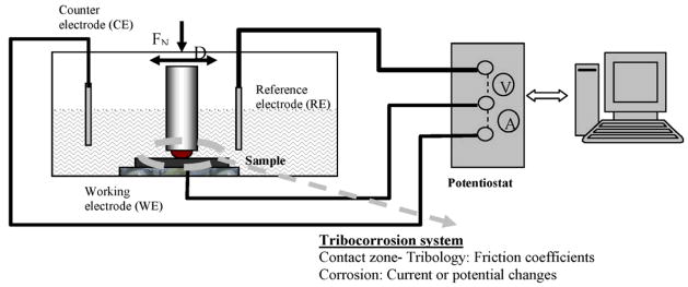
The materials degradation processes are significantly altered when the mechanical (e.g. friction, fatigue) reactions and corrosion are coupled. It is generally agreed that a corrosive environment accelerates the wear, and that chemical reactions are stimulated by the presence of friction and wear 40. The underlying reasons for the correlations between wear and corrosion as well as the detailed chemical processes are not fully understood. For instance, what are the relative roles of local pressure enhancements near a sliding tip on reactivity versus the temporary removal of protective chemisorbed species at a surface to leave more reactive and perhaps catalytically active metal surfaces in these processes? In the past decade, the interest in materials degradation in tribology systems with simultaneous mechanical and chemical reactions, i.e. tribocorrosion 41, has seen an expansion. Figure 4 shows a schematic of a pin-on-ball tribocorrosion test system 42, which includes an electro-chemical testing apparatus and a conventional pin-on-ball wear system. The potential and current dissipating at the articulating surface are monitored in real time during the rubbing between the pin the disk. A number of electrochemical tests, such as open circuit potential (OCP) measurement, potentiodynamic (PD) measurement, and electrochemical impedance spectroscopy (EIS) measurements, can be performed under controlled sliding condition 43, and agree well with the mathematical model by Papageorgiou and Mischler 44.
Figure 4.
Schematic of a tribocorrosion system. (from 42)
In general, the total materials loss (T) in a tribocorrosion system can be described by the following equation 41, 45,
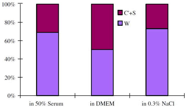
where W represents the wear in absence of corrosion, C represents the corrosion in absence of wear, and S is the interplay of the two components. W an be determined by measuring the materials under a negative penitential, i.e. cathodic protection, to eliminate corrosion; whilst C can be determined by measuring the corrosion rate for static system. Yan et al. 45 compared the wear volume of CoCrMo alloys under tribocorrosion tests and wear under cathodic protection. About 22% to 55% materials loss was attributed to corrosion-related reactions, see Figure 5. The authors suggested that the tribocorrosion is subject to competing passivation and re-passivation processes. Firstly, the wear track is passivated progressively by Cr oxide or an organo-composite formed electrochemically. Secondly, the passive layer is removed by mechanical delamination. Post ex facto SEM observation showed that smooth grooves are predominant in the wear test with cathodic protection; in contrast, pitting and adhesive wear are responsible in the wear with no cathodic protection. This indicates that cathodic potential suppressed the delamination of passive layer. It is worth noting that high-carbon CoCrMo alloys is less sensitive to the interplay of tribocorrosion compared to low-carbon CoCrMo and 316 stainless steels 45.
Figure 5.
Fraction of volume loss for high-carbon CoCrMo in 50% serum, DMEM, and 0.3% NaCl. The corrosion related volume loss is 22%–50%. (from 45)
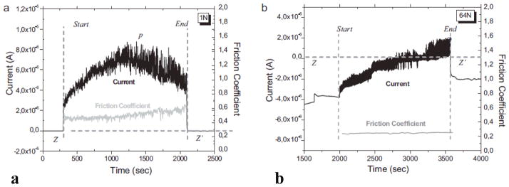
Mathew et al. 46 studied the tribocorrosion behavior of low-carbon CoCrMo alloys in both phosphate buffered solution (PBS) and bovine calf serum (BCS). The currents and friction coefficients are plotted in Figure 6 46; in which Figure 6a corresponds to the ball-on-plate test in PBS under an applied pressure of 372 MPa, whilst Figure 6b corresponds to the pin-on-ball test in BCS under an applied pressure of 752 MPa. In both systems, the currents abruptly rise to higher values when sliding started, which is attributed to the depassivation process. Due to rapid passivation, the currents immediately dropped back to values comparable to the initial ones when the sliding stopped. The passivation and repassivation led to an oscillation of the current and friction coefficients; the periodicity follows the cyclic motion 46. The sample weight loss reached its maximum at an applied pressure of 597 MPa for the test in serum, while for the test in PBS it increased monotonically, indicating the tribocorrosion is highly dependent on the media. In a recent study by Igual Muñoz and Mischler 47, it is reported that high-carbon alloys showed more wear than low-carbon alloys in the NaCl and PBS with albumin solution due to different third body behavior.
Figure 6.
Current and friction coefficient during tribocorrosion tests. (a) Ball-on-flat test in PBS under 373 MPa. (b) Pin-on-ball test in BCS under 752 MPa. (from 46)
It is worth noting that proteins may accelerate the corrosion by 20–60 fold under sliding contact 48. As a result, despite the better lubrication, the total material loss in serum is increased compared to NaCl aqueous solutions48.
5. Wear debris
It has been known that MoP hip prostheses produce polyethylene debris that has different biological effects than MoM metal debris. Polyethylene debris, due to its particle characteristics, i.e. size, shape and chemistry, causes cellular responses in the periprosthetic environment that lead to periprosthetic osteoclastic bone resorption (osteolysis). The polyethylene particles initiate an inflammatory cascade in macrophages and other cells, which loosens the implant. Loosening is commonly associated with pain and can necessitate revision surgery. MoM debris particles, on the other hand, tend to be smaller than polyethylene wear particles. The metal ions and nanoparticles can be easily transported throughout the lymphatic system. Metal wear particles tend to illicit a lymphocyte-dominated inflammatory response similar to polyethylene, however, triggering a cell-mediated immune response 2. MoM hip prostheses’ dissemination of metal particles and ions and the related adverse tissue reactions have become a concern over the last several years. Discolored and sometimes necrotic tissues are frequently observed near the hip replacements in revision operations; these tissues are believed to be affected by wear and/or corrosion products. There have been relatively few reports on MoM bearings wear particle characterization, due partly to the difficulties of collecting nanoparticles. Several protocols for isolating metal debris from periprosthetic tissues or serum for simulator tests were developed which use acid, base or enzymes. Of these techniques, the enzymatic digestion protocol prevails, as this process causes less damage to metal particles. Enzymatic removal of organic components usually utilizes the enzymes proteinase K and papain; the washing and incubation procedures have been described in details in Ref 15, 49–52.
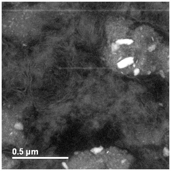
Figure 7 shows a Z-contrast micrograph of macrophage cells from a joint capsule tissue. Metallic particles, seen with bright contrast, were present inside the cells. The sizes of the particles are 50–150 nm. Doorn et al. 50 examined the nanoparticles generated by MoM total hip replacement in periprosthetic tissue from 13 patients with in-vivo time ranging from 7 months to 25 years. Nanocrystalline particles were found ranging from 6 to 744 nm in diameter with an average of 42 nm and exhibiting round to oval geometries. The chemical composition of the nanoparticles measured using EDS are, in general, similar to the original alloy, which is a mix of Co, Cr, and Mo elements. In addition, amorphous nanoparticles composed of Cr and O with little to no Co and Mo were also observed. Although the total wear volume is low, hip replacements in-vivo create a great number of particles as the particle size is small. It was calculated that ~6.7 × 10¹² to 2.5 × 10¹⁴ wear particles were produced annually 50. In contrast to the less mobile, large polyethylene wear debris, metal particles find their way throughout the entire body by dissolving in joint fluids 50. Urban et al. 10 examined 29 postmortem specimens as well as two biopsy specimens from living patents with hip replacements, and found that metal particles disseminated to liver, spleen and abdominal lymph nodes for the patients with failed hip replacements. The concentration of particles, however, was relatively low and the adverse effects were insignificant. Doorn et al. 50 suggested that metal wear debris can be dissolved via corrosion in joint fluid and excreted through blood and/or urine.
Figure 7.
Z-contrast micrograph of joint capsule tissue retrieved from a patient with MoM hip replacement. Metallic particles with bright contrast are present inside the cells.
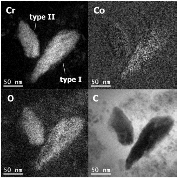
Similar results were obtained in simulator and pin-on-disc tests in bovine calf serum. The hip simulator tests performed by Firkins et al. 15 generated ~4 × 10¹² particles per million cycles, which is in good agreement with in-vivo estimations 50. The particles were observed to be 25–36 nm in size using TEM, which are comparable to those generated in-vivo. The number of wear particles generated by MoM is ~100 times higher than MoP hip replacements. Recently, Pourzal et al. 51 investigated the wear products of high-carbon wrought alloys after both reciprocating sliding and hip simulator tests. Three types of wear debris were identified using energy-filtered TEM, see Figure 8. Type I particles were composed of oxygen, chromium and a little cobalt; while type II nanoparticles were only chromium and oxygen. Note the absence of Mo, which is perhaps due to the high solubility of many molybdates such as the sodium salt. Both type I and type II nanoparticles were 30–80 nm in size, exhibiting irregular shapes. Type III nanoparticles, on the other hand, were Cr2O3 crystals less than 15 nm in size 51. Interestingly, Firkins et al. 15 and Catelas et al. 53 reported that wear particles after simulator tests in serum are primarily 30–50 nm large round chromium oxides with very few needle-like CoCrMo particles containing more Co than Cr. The number of these particles decreased with increasing loading cycles 53. While many of these reports showed an excess Cr nanoparticles, the underlying mechanism and the release of cobalt and molybdenum is not yet clear. In addition, it is often unclear whether the nanoparticles are wear products or due to some later precipitation process.
Figure 8.
Energy filtered TEM micrographs of two wear nanoparticles. (from 51)
It is worth noting that artifacts may be introduced during particle isolation and characterization. Firkins et al. 15 compared the wear particles obtained using enzymatic digestion and those generated in water-lubricated testing; it was suggested that metal particles may be oxidized and clumped due to the strong alkali used in the enzymatic digestion. Catelas et al. 52–54 systematically investigated the influence of digestion protocols on CoCrMo MoM wear particles. It was observed that Co ions were dissolved in to the solution when treated with alkaline, presumably forming Co(OH)2 54. Enzymatic treatment, on the other hand, preferentially attacks Cr. The authors found that digestion serum had the least reaction with wear particles with only a little Cr ion release after the treatment. Therefore, care needs to be taken when analyzing the wear particles, as the size, shape and chemistry can be altered during the wear particle isolation processes 54, and there is room for the development of improved analytical treatments.
6. Tribological Film
In addition to wear particles, thin layers of films are frequently generated in-vivo on CoCrMo MoM surfaces, which are known as tribological films or tribofilms. Wimmer et al. 55 examined 42 retrieved MoM replacements that failed due to aspetic loosening. More than 80% of the retrievals have tribological films sticking firmly to the surface, particularly in the rim region; these hip replacements showed no excessive wear. Knowledge of the structure and formation of the tribofilm was very limited. It was assumed that the tribological films are composed of something similar to denatured protein originated from the pseudo-synovial fluid according to the initial XPS results 11, 55–59.
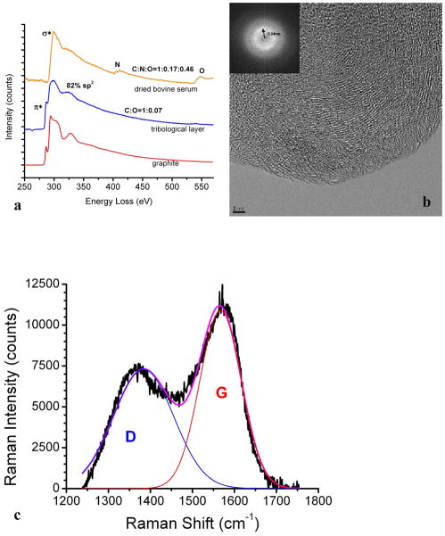
In a recent study, the tribofilms on retrieved hip implant and CoCrMo alloy after simulator tests in bovine calf serum were examined using TEM/EELS and Raman spectroscopy 60. The tribofilms were scrapped off using a micro-probe in a FIB system to avoid harsh ion beam damage in conventional ion beam milling. In order to reduce the damage induced by the electron beam exposure, the electron beam dose use was set to as low as ~58 electrons/Å2, and the results were compared to controls specimens of dried bovine calf serum to rule out artifacts 60. Figure 9a shows the EELS spectrum of the tribofilm from a retrieved MoM hip replacement 60. A strongπ* prepeak is present, which is a fingerprint of graphitic carbon 61, 62, indiciating that the triboflim is inorganic graphitic carbon. Using highly order pyrolytic graphite (HOPG) as a reference, the fraction of the sp2 bonding was calculated to be ~82% based on the EELS spectra 60, suggesting that most of the materials are decomposed to sp2 carbon. This is in agreement with the fact that no nitrogen and little oxgen (C/O ratio: 1:0.07) are present in the tribofilm, in contrast to the significant nitrogen and oxgen peaks in a control sample of dried bovine calf serum.
Figure 9.
(a) The EELS spectrum of tribological layer, dried bovine serum and graphite. The π*peak is present in the tribological layer. (b) HREM and the corresponding power spectrum show short-range ordered graphitic carbon layers. (c) Raman spectrum of tribological layer on a retrieved CoCrMo hip implant. G (red) and D (blue) lines are clearly present. (from 60)
Figure 9b 60 shows a high-resolution TEM image of the triboflim, in which short-range ordered fringes are clearly present. The spacing can be measured from the correspondent power spectrum in the inset picture to be 3.4 Å, which is the interplanar spacing of graphite. The tribofilm was further examined using Raman spectroscopy. Figure 9c shows the Raman spectrum of the tribolfilm. Two peaks at 1383 cm−1 and 1567 cm−1 are correlated to disordered sp2-carbon and sp3-bonded carbon, respectively 63; no other peaks are discernible. The graphitic carbon domain size was calculated based on the peak intensities (I) of G and D bands 49, 64, 65:
where C is a constant (4.4 nm for a 514.5 nm laser beam). It is calculated that the domain size of the graphitic carbon is ~4 nm, which agrees with the TEM observation.
The tribofilm should originate from the protein-contained fluid. It is well established that the protein-contained fluid provides an excellent lubricant for hip replacement 25, 58, 66–72. A fluid thin film can be formed at the counterfaces, as predicted by the well-known Hamrock-Dowson formula 73, at least partially separating the metallic surfaces. Mavraki and Cann 74, 75 measured the thickness of bovine serum under low (30 MPa) and high (200 MPa) contact pressures, and concluded that the fluid film was 5–50 nm under high pressure, and 40–50 nm thick for the low pressure contact. Dowson et al. 66 compared the lubrication effects of 25% and 100% serum, and found that the latter has remarkably better performance. This should not be attributed to the viscosity, as CMC and silicone fluid, which have higher viscosities, are less effective in lubrication 66. Scholes et al. 67, 76 also reported lower friction coefficients in protein-contained biological fluid than in synthetic lubricants for MoM bearings. It is evident that the proteins in the fluid play a critical role in the lubrication. As mentioned above, this cannot simply be the proteins themselves, but is a natural consequence of a well-known solid lubricant, graphitic carbon, at the metal surface.
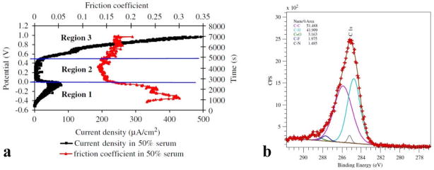
It has been shown that the tribofilm is essential in limiting the wear of MoM bearings 34. In 1966, Duff-Barclay and Spillman 77 observed solid carbonaceous deposit on metallic surfaces, and considered that they act as a solid lubricant. Yan et al. 48 showed in their tribocorrosion tests of CoCrMo alloy in 50% serum that a tribofilm is form in Region 2 (0.0–0.4 V) in Figure 10a. In this region, the current declines drastically, and the friction coefficient also a minimum 48. Thus the tribofilm may act beneficially as both the barrier to corrosion and lubricant to facilitate the sliding. Based on their XPS results 48, see Figure 10b, the tribofilm on CoCrMo after tribocorrosion tests in serum contains more than 50% of C 1s bonds. This is consistent with the observation of graphitic carbon on retrieved hip replacement. Graphite is a well-known solid lubricant in aqueous solutions 78, 79 and has been wildly used for applications such as automobile engines. The formation of this graphitic layer, as well as the details of its affects to the wear process, needs to be further investigated.
Figure 10.
(a) Anodic polarization curve (dark) and corresponding friction coefficient curve (red) for low-carbon CoCrMo. The low friction coefficient in Region 2 is attributed to the formation of tribofilm. (b) XPS spectrum of the tribofilm consisting of a large number of C 1s bonds. (from 48)
7. Possible Adverse Health Effects
CoCrMo metal debris can find its way around the entire body through the circulatory or lymphatic systems. It has been extensively reported that the Co ion level in the blood/serum increases for those patients with metal hip implant. Jacobs et al. 80 examined the Co and Cr concentration in serum and urine for 14 patients with metal hip replacements. The level of Cr in serum increased 3 fold after 2-year implantation, and increased 9 fold after 20 years of implantation; the Cr concentration urine increased 4 fold and 35 fold after 2 years and 20 years, respectively. The elevation of metal ions in serum has been largely substantiated 81 for instance by De Smet et al. 82 and Langton et al. 83 in a study of 4226 hip implants. In addition, metal particles have been observed in the organs distant from the hip replacement. There are many reports showing that metal wear debris disseminate to liver, spleen and lymph nodes. Since Cr doesn’t accumulate in tissues or bones with age, the Cr metal must originate from the wear and corrosion of hip implants 84, 85.
Possible adverse health effects caused by accumulated metal particles in the periprosthetic tissues include osteolysis 86, inflammation, pain, and pseudotumours 83, 87. The pathophysiology of metal debris-induced adverse tissue reactions has not been completely characterized. There can also be adverse remote tissue reactions to accumulated metal debris. Case et al. 88 reported that the accumulation of metal particle in lymph nodes cause structural changes such as necrosis and slight fibrosis; whereas the liver and spleen, on the other hand, did not show any sign of necrosis or fibrosis. The adverse influence by wear debris, such as inflammation, is primarily the immunological response provoked by the particles rather than toxic reactions 89; the pathological importance of metallic wear particles has been observed to be insignificant in some reports 10, 83. However, there are case reports which suggest neuro- and cardiotoxic from disseminated metal debris 90.
8. Summary and Perspectives
The clinical outcomes of MoM hip replacements are variable: some MoM hip replacements have shown excellent performance for over 20 years, while some MoM devices failed a few years after implantation due to aspetic loosening or adverse local tissue reactions. This disparity has multifactorial etiologies related to materials, device design, surgical technique, variability in the host response to debris, and activity level of the patient. All these variables need to be taken into account when modeling tribological process of hip replacement in-vivo. Since the wear particles ranged from submicron to tens of nanometers, an improved understanding of the nanotribology of all metal bearings is imperative as well as that of other classes of implants.
Even though the CoCrMo alloys used for medical implant comply with the ASTM standards, the microstructure of the alloys, particularly the hard phase, can be different due to the sluggish transformation of the CoCrMo system. Varied constituent carbide phases are formed depending on the heat treatment history, which influence the mechanical and corrosion performance. Only the chemical composition and basic mechanical properties are specified according to the ASTM standards. This appears to be insufficient; a thorough regulation of the microstructure and heat treatment history is desired to achieve a better consistency. In addition, a thorough understanding of the phase transformation of CoCrMo alloys is needed, as has been done for steels and many other alloys used in manufacturing.
Recent tribocorrosion studies of metal bearing have provided rich insight into the stimulated metal degradation with simultaneous wear and corrosion reactions. Two competing processes, i.e. passivation and re-passivation, are present during sliding. The wear particles are predominantly composed of Cr-compounds based on the reports from several groups. The absence of Mo in the wear products suggested that the removal of constituent Mo elements can be different from the Cr/Co elements. The ion release for CoCrMo alloys is primarily associated with Co ions. It is assumed that these ions are Co2+ when correlating the corrosion current to the mass loss using the Faraday’s law 46. It is essential to identify the chemical state of the metal ion produced by the electro-chemical reactions to backup this assumption. More importantly, from the health perspective, it is imperative to clarify whether or not the corrosion products contain Cr6+ ions, which are known to be highly toxic. Going beyond this, the mechanistic details of the reactions taking place are at a relatively primitive level compared to what is known for most other types of chemical reactions.
While the dependence of tribocorrosion on the applied load has been studied to some extent, the influence of the microstructure, e.g. grain size, second phases and chemical segregation to grain boundaries, on the tribocorrosion process is little understood. In tribocorrosion studies of CoCrMo hip replacements, the microstructure of the material was not monitored specifically, yet the microstructure could play a major role in wear. It is known that grain boundaries are more vulnerable to chemical attack due to impurities segregation and the large lattice misfit. Although a slight variation of chemical compositions of the matrix is less significant for galvanic corrosion in a static system, it can become important in fretting corrosion. Furthermore, the microstructure and metallurgical process may induce advanced galvanic corrosion. In a tribocorrosion process, it would not be surprising if the mixed hard phases in as-cast alloys would degrade in a different manner from the carbide in wrought alloys. Similarly, segregation of impurities at grain boundaries may also affect tribocorrosion. The tribocorrosion behavior of different microstructures in the CoCrMo system needs systematic investigation as there are many open questions.
It remains mysterious how the protein-contained fluid degrades to graphitic carbon during sliding, which may act as solid lubricant as well as protective layer. Wimmer et al. 11 calculated the temperature at articulating surface could be as high as ~70 °C at the hard carbon-carbide contact. This temperature alone does not seem to be responsible for the formation of graphitic carbon or other materials. We speculate whether the reaction is catalytic as the transition metals (Co) are good catalysts for eliminating water or ammonia from organic materials 91, 92.. A rich area for future work would be exploring the details of the reactions; better understanding these may lead to the next generation of devices. For instance, if we can control the microstructure/chemistry/corrosion/friction in a way where we deliberately have a protective low-friction layer at the surface which does not induce adverse physiological reactions, this would be a major advance. Nowadays we design almost routinely for high performance materials and lubricants for automobiles; humans are at least as important. It is worth remembering that a hip implant is often the difference between walking and leading a relatively normal life, and a wheelchair.
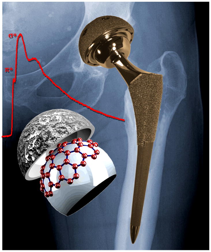
Scheme.
Acknowledgments
This work was funded by the NIH on grant number 1RC2AR058993-01 and the NSF on grant number CMMI-1030703. The authors are indebted to K. Shull, M. Mathew, and R. Pourzal for invaluable discussions.
References
- 1.Kurtz S, Ong K, Lau E, Mowat F, Halpern M. J Bone Joint Surg Am. 2007;89A:780–785. doi: 10.2106/JBJS.F.00222. [DOI] [PubMed] [Google Scholar]
- 2.Catelas I, Wimmer M, Utzschneider S. Semin Immunopathol. 2011;33:257–271. doi: 10.1007/s00281-011-0242-3. [DOI] [PubMed] [Google Scholar]
- 3.Rieker CB, Schon R, Kottig P. J Arthroplasty. 2004;19:5–11. doi: 10.1016/j.arth.2004.09.017. [DOI] [PubMed] [Google Scholar]
- 4.Jacobsson SA, Djerf K, Wahlstrom O. Clinical Orthopaedics and Related Research. 1996:S60–S68. doi: 10.1097/00003086-199608001-00006. [DOI] [PubMed] [Google Scholar]
- 5.Dorr LD, Wang ZI, Longjohn DB, Dubois B, Murken R. J Bone Joint Surg Am. 2000;82A:789–798. doi: 10.2106/00004623-200006000-00005. [DOI] [PubMed] [Google Scholar]
- 6.Delaunay CP, Bonnomet F, Clavert P, Laffargue P, Migaud H. Clin Orthop Relat R. 2008;466:340–346. doi: 10.1007/s11999-007-0045-y. [DOI] [PMC free article] [PubMed] [Google Scholar]
- 7.Eswaramoorthy V, Moonot P, Kalairajah Y, Biant LC, Field RE. J Bone Joint Surg Br. 2008;90B:1278–1283. doi: 10.1302/0301-620X.90B10.20378. [DOI] [PubMed] [Google Scholar]
- 8.2009, 58, 421–426.
- 9.Jacobs JJ, Skipor AK, Patteson LM, Hallab NJ, Paprosky WG, Black J, Galante JO. J Bone Joint Surg Am. 1998;80A:1447–1458. doi: 10.2106/00004623-199810000-00006. [DOI] [PubMed] [Google Scholar]
- 10.Urban RM, Jacobs JJ, Tomlinson MJ, Gavrilovic J, Black J, Peoc’h M. J Bone Joint Surg Am. 2000;82A:457–477. doi: 10.2106/00004623-200004000-00002. [DOI] [PubMed] [Google Scholar]
- 11.Wimmer MA, Loos J, Nassutt R, Heitkemper M, Fischer A. Wear. 2001;250:129–139. [Google Scholar]
- 12.Lopez HF, Saldivar-Garcia AJ. Metall Mater Trans A. 2008;39A:8–18. [Google Scholar]
- 13.Clemow AJT, Daniell BL. J Biomed Mater Res. 1979;13:265–279. doi: 10.1002/jbm.820130208. [DOI] [PubMed] [Google Scholar]
- 14.Nevelos J, Shelton J, Fisher J. Hip International. 2004;14:1–10. doi: 10.1177/112070000401400101. [DOI] [PubMed] [Google Scholar]
- 15.Firkins PJ, Tipper JL, Saadatzadeh MR, Ingham E, Stone MH, Farrar R, Fisher J. Bio-Med Mater Eng. 2001;11:143–157. [PubMed] [Google Scholar]
- 16.Liao Y, Pourzal R, Stemmer P, Wimmer MA, Jacobs JJ, Fischer A, Marks L. J Mech Behav Biomed. 2012;12:39–49. doi: 10.1016/j.jmbbm.2012.03.013. [DOI] [PMC free article] [PubMed] [Google Scholar]
- 17.Kilner T, Pilliar RM, Weatherly GC, Allibert C. J Biomed Mater Res. 1982;16:63–79. doi: 10.1002/jbm.820160109. [DOI] [PubMed] [Google Scholar]
- 18.Stemmer P, Pourzal R, Liao Y, Marks LD, Morlock M, Jacobs JJ, Wimmer MA, Fisher A. ASTM-STP. 2012 doi: 10.1016/j.jmbbm.2012.03.013. in print. [DOI] [PMC free article] [PubMed] [Google Scholar]
- 19.Smith SL, Dowson D, Goldsmith AAJ, PI Mech Eng H. 2001;215:161–170. doi: 10.1243/0954411011533724. [DOI] [PubMed] [Google Scholar]
- 20.Jin ZM. P I Mech Eng H. 2002;216:85–89. doi: 10.1243/0954411021536225. [DOI] [PubMed] [Google Scholar]
- 21.O’Kelly J, Unsworth A, Dowson D, Wright V. Engineering in Medicine. 1979;8:153–159. [Google Scholar]
- 22.Goldsmith AAJ, Dowson D, Isaac GH, Lancaster JG. P I Mech Eng H. 2000;214:39–47. doi: 10.1243/0954411001535228. [DOI] [PubMed] [Google Scholar]
- 23.Yan Y, Neville A, Dowson D, Williams S, Fisher J. P I Mech Eng J-J Eng. 2009;223:303–309. [Google Scholar]
- 24.Wimmer MA, Nassutt R, Sprecher C, Loos J, Tager G, Fischer A. P I Mech Eng H. 2006;220:219–227. doi: 10.1243/09544119JEIM117. [DOI] [PubMed] [Google Scholar]
- 25.Wang FC, Brockett C, Williams S, Udofia I, Fisher J, Jin ZM. Phys Med Biol. 2008;53:1277–1293. doi: 10.1088/0031-9155/53/5/008. [DOI] [PubMed] [Google Scholar]
- 26.Sun D, Wharton JA, Wood RJK, Ma L, Rainforth WM. Tribol Int. 2009;42:99–110. [Google Scholar]
- 27.Buscher R, Fischer A. Wear. 2005;259:887–897. [Google Scholar]
- 28.Zeng P, Rainforth WM, Inkson BJ, Stewart TD. Acta Mater. 2012;60:2061–2072. doi: 10.1002/jbm.b.31929. [DOI] [PubMed] [Google Scholar]
- 29.Merkle AP, Marks LD. Wear. 2008;265:1864–1869. [Google Scholar]
- 30.Merkle AP, Erdemir A, Eryilmaz OL, Johnson JA, Marks LD. Carbon. 2010;48:587–591. [Google Scholar]
- 31.Pastewka L, Moser S, Gumbsch P, Moseler M. Nat Mater. 2011;10:34–38. doi: 10.1038/nmat2902. [DOI] [PubMed] [Google Scholar]
- 32.Li QY, Tullis TE, Goldsby D, Carpick RW. Nature. 2011;480:233–U112. doi: 10.1038/nature10589. [DOI] [PubMed] [Google Scholar]
- 33.Yan Y, Neville A, Dowson D, Williams S, Fisher J. P I Mech Eng J-J Eng. 2010;224:997–1006. doi: 10.1243/09544119JEIM771. [DOI] [PubMed] [Google Scholar]
- 34.Wimmer MA, Fischer A, Buscher R, Pourzal R, Sprecher C, Hauert R, Jacobs JJ. J Orthop Res. 2010;28:436–443. doi: 10.1002/jor.21020. [DOI] [PubMed] [Google Scholar]
- 35.Gilbert JL, Mali S, Urban RM, Silverton CD, Jacobs JJ. J Biomed Mater Res B. 2012;100B:584–594. doi: 10.1002/jbm.b.31943. [DOI] [PubMed] [Google Scholar]
- 36.Gilbert JL, Buckley CA, Jacobs JJ. J Biomed Mater Res. 1993;27:1533–1544. doi: 10.1002/jbm.820271210. [DOI] [PubMed] [Google Scholar]
- 37.Julian LC, Munoz AI. Tribol Int. 2011;44:318–329. [Google Scholar]
- 38.Yan Y, Neville A, Dowson D. J Phys D Appl Phys. 2006;39:3200–3205. [Google Scholar]
- 39.Yan Y, Neville A, Dowson D. Wear. 2007;263:1105–1111. [Google Scholar]
- 40.Fischer TE. Annu Rev Mater Sci. 1988;18:303–323. [Google Scholar]
- 41.Landolt D, Mischler S, Stemp M. Electrochim Acta. 2001;46:3913–3929. [Google Scholar]
- 42.Mathew MT, Uth T, Hallab NJ, Pourzal R, Fischer A, Wimmer MA. Wear. 2011;271:2651–2659. [Google Scholar]
- 43.Ponthiaux P, Wenger F, Drees D, Celis JP. Wear. 2004;256:459–468. [Google Scholar]
- 44.Papageorgiou N, Mischler S. Tribol Lett. 2012 in press. [Google Scholar]
- 45.Yan Y, Neville A, Dowson D, Williams S. Tribol Int. 2006;39:1509–1517. [Google Scholar]
- 46.Mathew MT, Runa MJ, Laurent M, Jacobs JJ, Rocha LA, Wimmer MA. Wear. 2011;271:1210–1219. doi: 10.1016/j.wear.2011.01.086. [DOI] [PMC free article] [PubMed] [Google Scholar]
- 47.Munoz AI, Mischler S. J Mater Sci-Mater M. 2011;22:437–450. doi: 10.1007/s10856-010-4224-0. [DOI] [PubMed] [Google Scholar]
- 48.Yan Y, Neville A, Dowson D. Tribol Int. 2007;40:1492–1499. [Google Scholar]
- 49.Shanbhag AS, Jacobs JJ, Glant TT, Gilbert JL, Black J, Galante JO. J Bone Joint Surg Br. 1994;76B:60–67. [PubMed] [Google Scholar]
- 50.Doorn PF, Campbell PA, Worrall J, Benya PD, McKellop HA, Amstutz HC. J Biomed Mater Res. 1998;42:103–111. doi: 10.1002/(sici)1097-4636(199810)42:1<103::aid-jbm13>3.0.co;2-m. [DOI] [PubMed] [Google Scholar]
- 51.Pourzal R, Catelas I, Theissmann R, Kaddick C, Fischer A. Wear. 2011;271:1658–1666. doi: 10.1016/j.wear.2010.12.045. [DOI] [PMC free article] [PubMed] [Google Scholar]
- 52.Catelas I, Bobyn JD, Medley JB, Krygier JJ, Zukor DJ, Petit A, Huk OL. J Biomed Mater Res. 2001;55:320–329. doi: 10.1002/1097-4636(20010605)55:3<320::aid-jbm1020>3.0.co;2-3. [DOI] [PubMed] [Google Scholar]
- 53.Catelas I, Bobyn JD, Medley JB, Krygier JJ, Zukor DJ, Huk OL. J Biomed Mater Res A. 2003;67A:312–327. doi: 10.1002/jbm.a.10088. [DOI] [PubMed] [Google Scholar]
- 54.Catelas I, Bobyn JD, Medley JJ, Zukor DJ, Petit A, Huk OL. J Biomed Mater Res. 2001;55:330–337. doi: 10.1002/1097-4636(20010605)55:3<330::aid-jbm1021>3.0.co;2-y. [DOI] [PubMed] [Google Scholar]
- 55.Wimmer MA, Sprecher C, Hauert R, Tager G, Fischer A. Wear. 2003;255:1007–1014. [Google Scholar]
- 56.Chan FW, Bobyn JD, Medley JB, Krygier JJ, Yue S, Tanzer M. Clin Orthop Relat R. 1996:96–107. [PubMed] [Google Scholar]
- 57.McKellop H, Park SH, Chiesa R, Doorn P, Lu B, Normand P, Grigoris P, Amstutz H. Clin Orthop Relat R. 1996:S128–S140. doi: 10.1097/00003086-199608001-00013. [DOI] [PubMed] [Google Scholar]
- 58.Maskiewicz VK, Williams PA, Prates SJ, Bowsher JG, Clarke IC. J Biomed Mater Res B. 2010;94B:429–440. doi: 10.1002/jbm.b.31671. [DOI] [PubMed] [Google Scholar]
- 59.Mishina H, Kojima M. Wear. 2008;265:655–663. [Google Scholar]
- 60.Liao Y, Pourzal R, Wimmer MA, Jacobs JJ, Fischer A, Marks LD. Science. 2011;334:1687–1690. doi: 10.1126/science.1213902. [DOI] [PubMed] [Google Scholar]
- 61.Fink J, Mullerheinzerling T, Pfluger J, Bubenzer A, Koidl P, Crecelius G. Solid State Commun. 1983;47:687–691. [Google Scholar]
- 62.Berger SD, Mckenzie DR, Martin PJ. Phil Mag Lett. 1988;57:285–290. [Google Scholar]
- 63.Ferrari AC, Robertson J. Phys Rev B. 2000;61:14095–14107. [Google Scholar]
- 64.Tuinstra F, Koenig JL. J Chem Phys. 1970;53:1126–1130. [Google Scholar]
- 65.Chu PK, Li LH. Mater Chem Phys. 2006;96:253–277. [Google Scholar]
- 66.Dowson D, McNie CM, Goldsmith AAJ, PI Mech Eng C-J Mec. 2000;214:75–86. [Google Scholar]
- 67.Scholes SC, Unsworth A. P I Mech Eng H. 2000;214:49–57. doi: 10.1243/0954411001535237. [DOI] [PubMed] [Google Scholar]
- 68.Scholes SC, Unsworth A. Proceedings of the Institution of Mechanical Engineers Part H-Journal of Engineering in Medicine. 2006;220:687–693. doi: 10.1243/09544119JEIM21. [DOI] [PubMed] [Google Scholar]
- 69.Unsworth A. Physics in Medicine and Biology. 1978;23:253–268. doi: 10.1088/0031-9155/23/2/004. [DOI] [PubMed] [Google Scholar]
- 70.Widmer MR, Heuberger M, Voros J, Spencer ND. Tribol Lett. 2001;10:111–116. [Google Scholar]
- 71.Heuberger MP, Widmer MR, Zobeley E, Glockshuber R, Spencer ND. Biomaterials. 2005;26:1165–1173. doi: 10.1016/j.biomaterials.2004.05.020. [DOI] [PubMed] [Google Scholar]
- 72.Brown SS, Clarke IC. Tribol Lubr Technol. 2006;62:54–61. [Google Scholar]
- 73.Hamrock BJ, Dowson D. J Lubric Tech-T Asme. 1978;100:236–245. [Google Scholar]
- 74.Mavraki A, Cann PM. Tribol Int. 2011;44:550–556. [Google Scholar]
- 75.Myant C, Underwood R, Fan J, Cann PM. J Mech Behav Biomed. 2012;6:30–40. doi: 10.1016/j.jmbbm.2011.09.008. [DOI] [PubMed] [Google Scholar]
- 76.Scholes SC, Unsworth A, Hall RM, Scott R. Wear. 2000;241:209–213. [Google Scholar]
- 77.Duff-Barclay I, Spillman DT. Proceedings of the Institution of Mechanical Engineers. 1966;181:90–103. [Google Scholar]
- 78.Field SK, Jarratt M, Teer DG. Tribol Int. 2004;37:949–956. [Google Scholar]
- 79.Yen BK. Wear. 1996;192:208–215. [Google Scholar]
- 80.Jacobs JJ, Skipor AK, Doorn PF, Campbell P, Schmalzried TP, Black J, Amstutz HC. Clin Orthop Relat R. 1996:S256–S263. doi: 10.1097/00003086-199608001-00022. [DOI] [PubMed] [Google Scholar]
- 81.Brodner W, Bitzan P, Meisinger V, Kaider A, GottsaunerWolf F, Kotz R. J Bone Joint Surg Br. 1997;79B:316–321. doi: 10.1302/0301-620x.79b2.7326. [DOI] [PubMed] [Google Scholar]
- 82.De Smet K, De Haan R, Calistri A, Campbell PA, Ebramzadeh E, Pattyn C, Gill HS. J Bone Joint Surg Am. 2008;90A:202–208. doi: 10.2106/JBJS.H.00672. [DOI] [PubMed] [Google Scholar]
- 83.Langton DJ, Joyce TJ, Jameson SS, Lord J, Van Orsouw M, Holland JP, Nargol AVF, De Smet KA. J Bone Joint Surg Br. 2011;93B:164–171. doi: 10.1302/0301-620X.93B2.25099. [DOI] [PubMed] [Google Scholar]
- 84.Langkamer VG, Case CP, Heap P, Taylor A, Collins C, Pearse M, Solomon L. J Bone Joint Surg Br. 1992;74:831–839. doi: 10.1302/0301-620X.74B6.1447243. [DOI] [PubMed] [Google Scholar]
- 85.Shahgaldi BF, Heatley FW, Dewar A, Corrin B. J Bone Joint Surg Br. 1995;77B:962–966. [PubMed] [Google Scholar]
- 86.Huber M, Reinisch G, Zenz P, Zweymuller K, Lintner F. J Bone Joint Surg Am. 2010;92A:1720–1731. doi: 10.2106/JBJS.I.00695. [DOI] [PubMed] [Google Scholar]
- 87.Caicedo MS, Desai R, McAllister K, Reddy A, Jacobs JJ, Hallab NJ. J Orthop Res. 2009;27:847–854. doi: 10.1002/jor.20826. [DOI] [PubMed] [Google Scholar]
- 88.Case CP, Langkamer VG, James C, Palmer MR, Kemp AJ, Heap PF, Solomon L. J Bone Joint Surg Br. 1994;76B:701–712. [PubMed] [Google Scholar]
- 89.Jacobs JJ, Urban RM, Hallab NJ, Skipor AK, Fischer A, Wimmer MA. J Am Acad Orthop Sur. 2009;17:69–76. doi: 10.5435/00124635-200902000-00003. [DOI] [PubMed] [Google Scholar]
- 90.Tower SS. J Bone Joint Surg Am. 2010;92A:2847–2851. doi: 10.2106/JBJS.J.00125. [DOI] [PubMed] [Google Scholar]
- 91.Woodman JL, Black J, Jiminez SA. J Biomed Mater Res. 1984;18:99–114. doi: 10.1002/jbm.820180110. [DOI] [PubMed] [Google Scholar]
- 92.Kocijan A, Milosev I, Pihlar B. J Mater Sci-Mater M. 2003;14:69–77. doi: 10.1023/a:1021505621388. [DOI] [PubMed] [Google Scholar]
- 93.Handbook of Chemistry Physics. CRC, Boca Raton; Florida: 1998. [Google Scholar]


