

Abstract
The purpose of this study is to assess fidelity of radiation delivery between high and low dose rates of the flattening filter free (FFF) modes of a new all-digital design medical linear accelerator (Varian TrueBeam™), particularly for plans optimized for volumetric modulated arc therapy (VMAT). Measurements were made for the two energies of flattening filter free photon beams with a Varian TrueBeam™ linac: 6 MV (6 XFFF) at 400 and 1400 MU/min, and 10 MV (10 XFFF) at 400 and 2400 MU/min. Data acquisition and analysis was performed with both ionization chambers and diode detector system Delta4, for square radiation fields and for 8 VMAT treatment plans optimized for SBRT treatment of lung tumors. For the square fields, a percent dose difference between high and low dose rate of the order of 0.3-0.4% for both photon energies was seen with the ionization chambers, while the contribution to the difference from ion recombination was found to be negligible. For both the VMAT and square-field deliveries, the Delta4 showed the same average percent dose difference between the two dose rates of ~0.8% and ~0.6% for 10 MV and 6 MV, respectively, with the lower dose rate values giving the greater measured dose compared to the high dose rate. Thus, the VMAT deliveries introduced negligible dose differences between high and low dose rate. Finally, reproducibility of dose measurements was good for both energies.
Keywords: Delta4, flattening filter free, truebeam
Introduction
A TrueBeam STx system is a commercial medical linac which can operate both in with flattening filter (WFF) and flattening filter free (FFF) mode. It's FFF mode can deliver treatments 2.4 to 4 times faster with a dose delivery rate of up to 2,400 monitor units per minute (MU/min) in the FFF mode; more than double the dose rate of most other radiosurgery systems.
Several previous studies have investigated the physical properties of FFF medical linacs, such as changes in <dmax>, the depth of maximum dose deposition, lateral dose profiles and energy spectrum.[1–3] Various advantages of FFF beams compared to conventional beams have been identified[4] such as reduced out-of-field dose for treatment delivery, reduced head scatter, reduced leakage from the multi-leaf collimator (MLC), improved contrast for portal imaging,[5] reduced variations in beam steering and bending magnet currents,[6] as well as the increased dose rate and consequently reduced treatment times.
In particular, the flattening filter is one of the main sources of scattered radiation which contributes up to 10% of the total photon fluence[7–10] and electron contamination which alters the depth of maximum dose with increasing field size.[11] This enables for FFF, a significant improvement in out-of-field dose for small fields, which can be attributed to the change in the photon spectra,[12–14] when the flattening filter is removed from the beamline.[3] The significance of other secondary byproducts, such as neutrons, from interactions of the primary beam with high atomic number materials of the gantry head has been confirmed with computational and experimental studies for higher photon energies.[15–18] By studying the effect of the FFF beams on the tenth-value-layer and the scattered dose inside and outside the treatment room, Kry et al.[15,16] and Vassiliev et al.[18] reported reduced primary and secondary barrier thickness requirements of the order 10%-20% when using linacs with the flattening filter removed. Additionally leaf transmission is slightly reduced for FFF beams over conventional.[19] Since the absence of the flattening filter (FF) reduces the scattered radiation, electron contamination, off-axis softening and rather flat output factor variation with field size, we could speculate that unflattened beams would improve the algorithmic dose calculations for intensity modulated radiation therapy (IMRT) fields and ease the computational modeling of the beam.[20,21]
There is general agreement that removal of the FF increases the photon fluence and hence the dose per pulse,[6,22–24] resulting in reduced net treatment delivery time. Because of that characteristic FFF linacs are appealing for radiosurgery and provide improved patient comfort. Fu et al.[25] investigated the delivery time of IMRT fields with and without the FF and demonstrated that the reduction of the delivery time becomes clinically significant for higher than conventional fraction dose. Reduced treatment times could provide an advantageous motion management also because the likelihood of motion decreases with the shorter time for treatment. This is important in stereotactic body radiation therapy due to respiratory motion.[26,27] Medical linacs with dose rates as high as 2400 cGy/min at 10 MV and 1400 cGy/min at 6 MV have been clinically installed in many institutions. Hrbacek et al.[28] described commissioning results obtained with the Varian TrueBeam system in a FFF mode and the anisotropic analytical algorithm. However, in reality, little is known about the accuracy of delivery at these high dose rates, particularly for complex treatment plans with simultaneous motion of gantry and MLC aperture.
In this study we provide for the first time a quantitative dynamic dose delivery comparison of Varian TrueBeamTM operating at FFF mode for low and high dose rates, for the high dose fractions characteristic of few- and single-fraction stereotactic radiotherapy. The FFF modes operate at photon energies of 6 and 10 MV, designated here as 6 and 10 XFFF. Generally excellent agreement was found between 400 and 2400 MU/min delivery of 10 XFFF and between 400 and 1400 MU/min delivery of 6 XFFF for the eight lung SBRT VMAT plans considered in this study.
Materials and Methods
The TrueBeam system
In this work a TrueBeam medical linac (Varian Medical Systems, Palo Alto, CA), equipped with a high-definition multileaf collimator (HDMLC-120) was used. In addition to conventional 6 and 15 MV beams with filter, a TrueBeam system offers FFF beams with much higher than previously available dose rates (for 6 MV, up to 1400 MU/min; for 10 MV, up to 2400 MU/min). Additionally it is equipped with an advanced digital control system which reduces the dosimetric errors by prospectively limiting the leaf speed in the MLC trajectories.[29]
Planning software
VMAT (Varian Medical Systems, Palo Alto, CA) has become available for the treatment and delivery of the arc-dynamic IMRT. It incorporates capabilities such as variable dose-rate, variable gantry speed, and fast dynamic multileaf collimators (DMLC), to optimize dose conformity, delivery efficiency, accuracy and reliability.[30] VMAT is regarded as a complex treatment because the leaves of the MLC are continuously moving, and the gantry speed and dose rate can be modulated. Five clinically used single-arc plans for lung at 10 XFFF and three at 6 XFFF were randomly selected from our database to investigate dose discrepancy between high and low dose rate (DR). All patient plans were optimized using the Eclipse v.8.9 treatment planning system (TPS). For all plans the prescribed dose was 12.5 Gy and each plan was optimized accordingly in order to achieve the desired target dose and critical structures sparing. Dose calculations were performed using the anisotropic analytical algorithm (AAA). All plans were delivered on a Varian TrueBeam system and the dose rate was constant through the delivery of each plan.
Dose acquisition
The evaluation of the dosimetric comparison for low and high dose rate, of the FFF mode at 6× and 10×, was performed for both square fields and VMAT plans. Point dose measurements for square radiation fields of dimension 10 × 10 cm2 were acquired with an ionization chamber delivering 200 MU for two setups. The two setups were devised to test, within constraints of practicality, using different yet conventional dose rates for high-efficiency collection by ion chamber detectors to measure the relative response to machine output per monitor unit (MU) from the FFF beams at different MU/min. Firstly, a pinpoint (PTW TX 31014, inter-electrode spacing 0.85 mm, volume 0.015 cm3) and a Farmer (PTW N 30013, inter-electrode spacing 2.5 mm, volume 0.6 cm3) ionization chamber were respectively located with a source-to-surface distance (SSD) 380 cm, depth and backscatter of 15 cm solid water, and also in a second setup at an SSD of 189 cm, backscatter 10 cm, at two depths: 30 and 3 cm. For the VMAT evaluation, 5 SBRT plans for lung were generated with the Eclipse treatment planning system (TPS) (Varian Medical Systems, Palo Alto, CA) for 10 XFFF and 3 SBRT plans for 6 XFFF. Each plan consisted of a single arc and each was delivered at both low (400 MU/min) and high dose rate (6 XFFF: 1400 MU/min, 10 XFFF: 2400 MU/min). The dose measurement was done with a Delta4 3D phantom that consists of 1069 silicon p-type diodes detectors mounted in two perpendicular planes (main and secondary board). These planes are embedded in a cylindrical PMMA phantom. The sensitive volume of each of the detector planes covers an area of 20 × 20 cm2. The resolution in the central 6 × 6 cm2 area is 5 mm and is 10 mm in the outer area. Further details on the design, accuracy and use of Delta4 phantom have previously been discussed.[31,32]
Dosimetric Comparison
The dosimetric comparison was established in the relative percentage dosimetric error (RDE) described as follows:
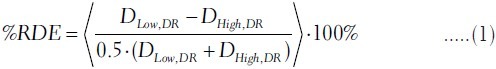
where DLow,DR and DHigh,DR is the measured dose at each diode detector of the Delta4 at the low and high dose rate (DR) delivery, respectively. The brackets in equation 1 indicate an averaging operator: The %RDE is the average percent relative dosimetric difference between the high and low DR for the same photon energy over all the diode detectors of the Delta4 for which the measured dose is above a minimum value. We shall refer to that minimum dose value as the threshold. Previous studies have considered a fixed value of dose as a threshold or a percentage equal to 10% of the maximum dose for IMRT plans.[33,34] In our study we considered as a threshold both 10% and 1% of the maximum dose, Dmax, as measured with the Delta4 for each VMAT plan. However for illustrative purposes in our further analysis, we shall provide the %RDE for a wider spectrum of the threshold values.
Results
Delta4 performance compared to point measurements for square fields
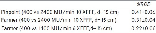
A set of experiments were performed with square radiation fields and ionization chamber for 6 XFFF and 10 XFFF with an emphasis given at 10 XFFF due to its clinical significance for SBRT. Firstly, the chamber was located at depth of 15 cm and SSD of 380 cm. At that distance and depth the actual dose rate at the detector position is reduced by a factor of ~ 20 relative to Dmax at isocenter. Table 1 reports the %RDE for point measurements with both Farmer and pinpoint ionization chamber. We notice that the %RDE measured using the pinpoint for the 2400 dose rate 10 XFFF was 0.10% ± 0.07% (standard error) higher than that measured with the Farmer, i.e., not significantly different, while the %RDE is reduced slightly by 0.09% ± 0.07% (standard error) for the 1400 dose rate 6 XFFF compared to the 2400 dose rate 10 XFFF, when measured with the Farmer chamber.
Table 1.
Point dose measurements for 10×10 cm2 radiation field at SSD=380 cm
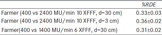
The experiment was repeated for the same field size but with an SSD = 189 cm. In that case the actual delivered dose rate was higher than previously due to the decreased SSD. The %RDE was essentially the same for both energies [Table 2]. Finally, we increased the delivered dose at the measurement point by decreasing the ionization chamber depth distance from 30 to 3 cm and found that the %RDE was essentially the same as previously.
Table 2.
Point dose measurements for 10 × 10 cm2 radiation field at SSD=189 cm
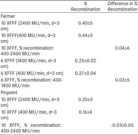
Since some or all of the dosimetric difference between high and low dose rate might be attributable to differences in the recombination factor, we examined that hypothesis by following the procedure described in AAPM TG-51 report[35] and repeated the experiments for two voltage values (300 and 150 V) at high and low dose rate for both energies. Table 3 reports the results of the measurements with a Farmer ionization chamber. We found that the percentage recombination was essentially the same with mean 0.42% and standard deviation ±0.05%. To further test the dependence of recombination on dose rate, the measurements were repeated with a pinpoint chamber which has a smaller inter-electrode distance and consequently smaller recombination factor. The difference in percent recombination between the two dose rates was 0.04 ± 0.6 and 0.03 ± 5 for 10 and 6 XFFF respectively, while for the pinpoint was -0.03% ± 5 This experiment shows that the measurement variability in output between the different dose rates cannot be accounted for by differences in the recombination factor.
Table 3.
Effect of chamber voltage on the measured dose at SSD=189 cm
Square-field irradiations (20 × 20 cm) were also measured with the Delta4 centered at SAD 100 cm. The mean values for the differences in the dose readings between the two dose rates were 0.91± 17 XFFF) and 0.64± 11% (6 XFFF). A linear dose response was confirmed for both 10 XFFF and 6 XFFF (data not shown).
Dosimetric difference between low and high dose rate for 6 and 10 mv X-rays in fff mode for VMAT
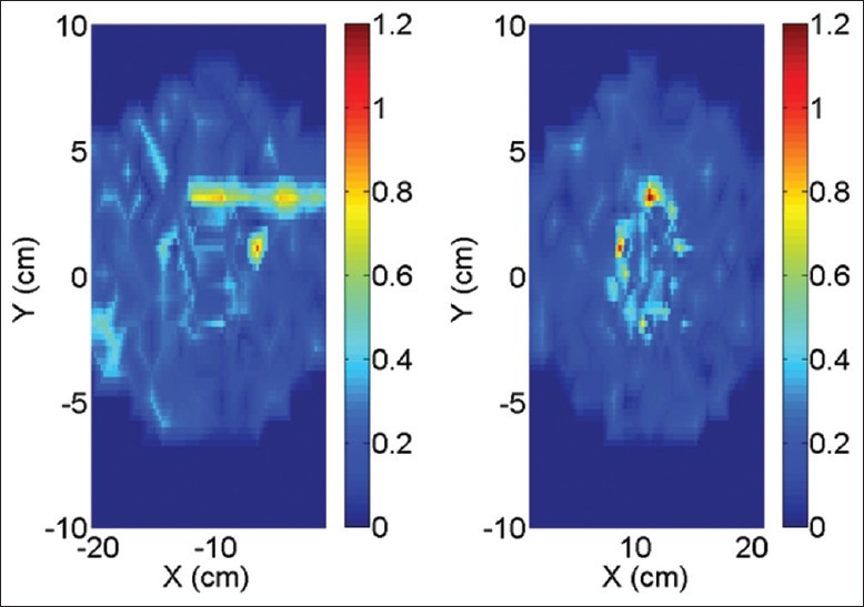
Dosimetric comparison between high and low dose rate was examined for VMAT deliveries. In Figure 1a and b the dose differences between the low and high dose rate deliveries of a VMAT plan are shown, for 6 and 10 MV respectively. Diodes measuring less than 1% of DMax were excluded from the diagrams. We notice that for some areas of the field, the %RDE is as high as 1.5%.
Figure 1.

VMAT planar distribution of the RDE for the two detector planes of the Delta4 for 6 XFFF (a) and 10 XFFF (b)
Eight patient treatment plans were considered in our analysis. Figure 2a illustrates the average %RDE for one patient as a function of the threshold, expressed as a percentage of the maximum dose DMax. We observe that the %RDE tends asymptotically towards a steady value after a threshold of ~10% of DMax for both energies. Figure 2b shows the distribution of the RDE as a function of the measured dose. The larger variability of the %RDE occurs for the diodes in the low dose region.
Figure 2.

(a) Average % RDE for one patient VMAT plan as a function of threshold for 10 XFFF (solid line) and 6 XFFF (dashed line). (b) Distribution of % RDE as function of the measured dose at each diode
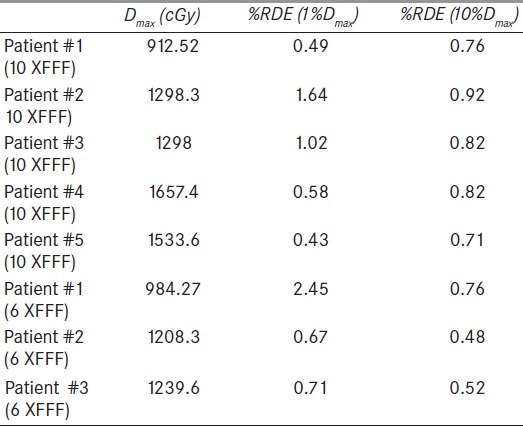
Table 4 reports the results for the 8 VMAT treatment plans considered in this study for both energies. The parentheses in the two right-most column headers denote the threshold percentage of Dmax used for calculation of the mean %RDE. Below-threshold doses were excluded from the calculations. The %RDE averaged over the VMAT plans were 0.83 ± 0.51% and 1.28 ± 1.02% for 10 XFFF and 6 XFFF, respectively, for a threshold of 1% of Dmax, and 0.81 ± 0.08% and 0.59 ± 0.15%, respectively, for a threshold of 10% of Dmax. We observe that the %RDE are more irregular with the 1%, as compared to the 10% of Dmax threshold, which might be attributed to the greater relative effect of stochastic fluctuations of the Delta4 diode measurements in the low dose regions.
Table 4.
Maximum dose (Dmax) and mean %RDE for the VMAT plans. The parentheses in the two right-most column headers denote the threshold percentage of Dmax used for calculation of the mean %RDE
Finally Figure 3 illustrates the %RDE as a function of the dose rate for both square radiation fields and VMAT plans as measured with the Delta4. For comparison we have also included the %RDE calculated with an ionization chamber. Similar trends appeared for both energies. In particular, VMAT plans measured with the Delta4 showed slightly higher %RDE than square fields measured with the Delta4, which showed higher %RDE than square fields measured with ion chambers, and all %RDEs increased with increasing dose rate.
Figure 3.

% RDE (%1Dmax) as a function of the dose rate for 10 XFFF. (a) and 6 XFFF. (b) Solid line (triangle markers) represent measurements with ionization chamber for square fields. Dashed and dotted line show measurements of square fields with Delta4 for 200 MU (circle markers) and 2500 MU (square markers) delivered. Dashed line (diamond markers) show results for VMAT plans measured with the Delta4
Reproducibility and dose dependence of dosimetric error
To examine the reproducibility of the measurements, we repeated the delivery of one plan five times at 10 XFFF and dose rate 2400 MU/min. Figure 4 illustrates the spatial distribution of the standard deviation of the measured dose at each diode detector.
Figure 4.
Spatial distribution of percent relative standard deviation of measured dose at each detector of Delta4. Left and right panel corresponds to the main board and secondary wing of the Delta4
Discussion and Conclusions
In this work we investigated the fidelity of dosimetric accuracy of TrueBeam in FFF mode for 6 and 10 MV photon energy in VMAT plans. The evaluation was established on the basis of relative percentage dose error between high and low dose rate. In particular, from point dose measurements with an ionization chamber and square radiation fields, the error was of the order of 0.3-0.4%. Contribution to this error from ion recombination was negligible as verified following the procedures of the TG-51 report. We need to stress that previous studies[36] have demonstrated the underestimation of the recombination factor based on the two-voltage method but for higher dose rates the error is negligible. Square radiation fields were measured with the Delta4. The linearity of its response with respect to the delivered dose was confirmed, and average %RDEs of ~0.91% and 0.64% for 10 XFFF and 6 XFFF respectively, between high and low dose rate were recorded.
Our analysis was extended to VMAT plans measured with the Delta4. The average %RDE over 8 delivered SBRT plans in total, was calculated for both 10 XFFF (~0.83%) and 6 XFFF (~1.3%) which was higher than those of the square radiation fields. From Figure 2a we may observe that the %RDE tends asymptotically towards a constant %RDE value equal to 0.8% for 10 XFFF and 0.6% for 6 XFFF when a dose cutoff equal (or larger) to 10% of Dmax was considered. Finally, the reproducibility of the delivered dose appeared satisfactory for both photon energies.
In this study, only single arc plans were considered. For VMAT deliveries, the %RDE was greater compared to square field radiations as measured with the Delta4. By use of more arcs per fraction, the dose modulation per arc would be reduced. This would likely result in higher gantry speed and less MLC motion. Such clinical deliveries were not tested in the present study.
The accuracy (average error) and the precision (the variation of the error) of the dose delivery are of interest for patient treatment. Robinson et al.[33] have demonstrated that an explicit correction factor would be necessary for the 6 XFFF mode with a diode array when compensators were used for beam modulation. The systematic error due to the Delta4 and the output of the TrueBeam operating at high dose rate could be corrected with an approach similar to that proposed by Bertelsen et al.[34]
In conclusion, it appears that there is a dosimetric error of ~0.3-0.4% introduced by the high dose rate FFF modes, assuming as gold standard the results from ionization chamber measurements. It was found that the Delta4 systematically overestimated the dose-rate dependency error by ~0.5%. No additional dose-rate dependent discrepancies were found from VMAT delivery. The biological and clinical effects due to the small relative dose differences between high and low dose rate deliveries are expected to be minimal.
Acknowledgment
The authors are very grateful to the diagnostic radiographers, radiologists, radiation oncologists and medical physicists for their assistance, encouragement and guidance throughout the entire period of study.
Footnotes
Source of Support: Nil
Conflict of Interest: None declared.
References
- 1.Sixel KE, Faddegon BA. Calculation of x-ray spectra for radiosurgical beams. Med Phys. 1995;22:1657–61. doi: 10.1118/1.597426. [DOI] [PubMed] [Google Scholar]
- 2.Sixel KE, Podgorsak EB. Buildup region and depth of dose maximum of megavoltage X-ray beams. Med Phys. 1994;21:411–6. doi: 10.1118/1.597305. [DOI] [PubMed] [Google Scholar]
- 3.Titt U, Vassiliev ON, Pönisch F, Dong L, Liu H, Mohan R. A flattening filter free photon treatment concept evaluation with Monte Carlo. Med Phys. 2006;33:1595–602. doi: 10.1118/1.2198327. [DOI] [PubMed] [Google Scholar]
- 4.Sharma SD. Unflattened photon beams from the standard flattening filter free accelerators for radiotherapy: Advantages, limitations and challenges. J Med Phys. 2011;36:123–5. doi: 10.4103/0971-6203.83464. [DOI] [PMC free article] [PubMed] [Google Scholar]
- 5.Tyner E, McClean B, McCavana P, af Wetterstedt S. Experimental investigation of the response of an a-Si EPID to an unflattened photon beam from an Elekta Precise linear accelerator. Med Phys. 2009;36:1318–29. doi: 10.1118/1.3089424. [DOI] [PubMed] [Google Scholar]
- 6.Cashmore J. The characterization of unflattened photon beams from a 6 MV linear accelerator. Phys Med Biol. 2008;53:1933–46. doi: 10.1088/0031-9155/53/7/009. [DOI] [PubMed] [Google Scholar]
- 7.Zanini A, Durisi E, Fasolo F, Ongaro C, Visca L, Nastasi U, et al. Monte Carlo simulation of the photoneutron field in linac radiotherapy treatments with different collimation systems. Phys Med Biol. 2004;49:571–82. doi: 10.1088/0031-9155/49/4/008. [DOI] [PubMed] [Google Scholar]
- 8.Sheikh-Bagheri D, Rogers DW. Monte Carlo calculation of nine megavoltage photon beam spectra using the BEAM code. Med Phys. 2002;29:391–402. doi: 10.1118/1.1445413. [DOI] [PubMed] [Google Scholar]
- 9.Chaney EL, Cullip TJ, Gabriel TA. A Monte Carlo study of accelerator head scatter. Med Phys. 1994;21:1383–90. doi: 10.1118/1.597194. [DOI] [PubMed] [Google Scholar]
- 10.Zhu XR, Kang Y, Gillin MT. Measurements of in-air output ratios for a linear accelerator with and without the flattening filter. Med Phys. 2006;33:3723–33. doi: 10.1118/1.2349695. [DOI] [PubMed] [Google Scholar]
- 11.Georg D, Julia F, Briot E, Huyskens D, Wolff U, Dutreix A, et al. Dosimetric comparison of an integrated multileaf-collimator versus a conventional collimator. Phys Med Biol. 1997;42:2285–303. doi: 10.1088/0031-9155/42/11/020. [DOI] [PubMed] [Google Scholar]
- 12.Jeraj R, Mackie TR, Balog J, Olivera G, Pearson D, Kapatoes J, et al. Radiation characteristics of helical tomotherapy. Med Phys. 2004;31:396–404. doi: 10.1118/1.1639148. [DOI] [PubMed] [Google Scholar]
- 13.Mesbahi A, Nejad FS. Monte Carlo study on a flattening filter-free 18-MV photon beam of a medical linear accelerator. Radiat Med. 2008;26:331–6. doi: 10.1007/s11604-008-0234-y. [DOI] [PubMed] [Google Scholar]
- 14.Lind M, Knoos T, Ceberg C, Wieslander E, McClean B, Georg D, et al. Photon beam characteristics at the Monitor chamber level in a flattening filter free linac: A Monte Carlo study. Radiother Oncol. 2009;92:S57. [Google Scholar]
- 15.Kry SF, Howell RM, Titt U, Salehpour M, Mohan R, Vassiliev ON, et al. Energy spectra, sources, and shielding considerations for neutrons generated by a flattening filter-free Clinac. Med Phys. 2008;35:1906–11. doi: 10.1118/1.2905029. [DOI] [PubMed] [Google Scholar]
- 16.Kry SF, Titt U, Pönisch F, Vassiliev ON, Salehpour M, Gillin M, et al. Reduced neutron production through use of a flattening-filter-free accelerator. Int J Radiat Oncol Biol Phys. 2007;68:1260–4. doi: 10.1016/j.ijrobp.2007.04.002. [DOI] [PubMed] [Google Scholar]
- 17.Mesbahi A. A Monte Carlo study on neutron and electron contamination of an unflattened 18-MV photon beam. Appl Radiat Isot. 2009;67:55–60. doi: 10.1016/j.apradiso.2008.07.013. [DOI] [PubMed] [Google Scholar]
- 18.Vassiliev ON, Titt U, Kry SF, Mohan R, Gillin MT. Radiation safety survey on a flattening filter-free medical accelerator. Radiat Prot Dosimetry. 2007;124:187–90. doi: 10.1093/rpd/ncm179. [DOI] [PubMed] [Google Scholar]
- 19.Kragl G, af Wetterstedt S, Knäusl B, Lind M, McCavana P, Knöös T, et al. Dosimetric characteristics of 6 and 10 MV unflattened photon beams. Radiother Oncol. 2009;93:141–6. doi: 10.1016/j.radonc.2009.06.008. [DOI] [PubMed] [Google Scholar]
- 20.Cho W, Kielar KN, Mok E, Xing L, Park JH, Jung WG, et al. Multisource modeling of flattening filter free (FFF) beam and the optimization of model parameters. Med Phys. 2011;38:1931–42. doi: 10.1118/1.3560426. [DOI] [PMC free article] [PubMed] [Google Scholar]
- 21.Fippel M, Haryanto F, Dohm O, Nüsslin F, Kriesen S. A virtual photon energy fluence model for Monte Carlo dose calculation. Med Phys. 2003;30:301–11. doi: 10.1118/1.1543152. [DOI] [PubMed] [Google Scholar]
- 22.Stathakis S, Esquivel C, Gutierrez A, Buckey CR, Papanikolaou N. Treatment planning and delivery of IMRT using 6 and 18 MV photon beams without flattening filter. Appl Radiat Isot. 2009;67:1629–37. doi: 10.1016/j.apradiso.2009.03.014. [DOI] [PubMed] [Google Scholar]
- 23.Ishmaelparsai E, Pearson D. Consequences of removing the flattening filter from linear accelerators in generating high dose rate photon beams for clinical applications. Nuclear Instruments and Methods in Physics Research Section B. Beam Interactions with Materials and Atoms. 2007;261:755–9. [Google Scholar]
- 24.Vassiliev ON, Titt U, Pönisch F, Kry SF, Mohan R, Gillin MT. Dosimetric properties of photon beams from a flattening filter free clinical accelerator. Phys Med Biol. 2006;51:1907–17. doi: 10.1088/0031-9155/51/7/019. [DOI] [PubMed] [Google Scholar]
- 25.Fu W, Dai J, Hu Y, Han D, Song Y. Delivery time comparison for intensity-modulated radiation therapy with/without flattening filter: A planning study. Phys Med Biol. 2004;49:1535–47. doi: 10.1088/0031-9155/49/8/011. [DOI] [PubMed] [Google Scholar]
- 26.Partridge M, Tree A, Brock J, McNair H, Fernandez E, Panakis N, et al. Improvement in tumour control probability with active breathing control and dose escalation. A modeling study. Radiother Oncol. 2009;91:325–9. doi: 10.1016/j.radonc.2009.03.017. [DOI] [PubMed] [Google Scholar]
- 27.Stock M, Kontrisova K, Dieckmann K, Bogner J, Georg D. Development and application of real-time monitoring and feed-back system for deep inspiration breath hold based on external marker tracking. Med Phys. 2006;33:2868–77. doi: 10.1118/1.2219775. [DOI] [PubMed] [Google Scholar]
- 28.Hrbacek J, Lang S, Klock S. Commissioning of photon beams of a flattening filter-free accelerator and the accuracy of beam modeling using an anisotropic analytical algorithm. Int J Radiat Oncol Biol Phys. 2011;80:1228–37. doi: 10.1016/j.ijrobp.2010.09.050. [DOI] [PubMed] [Google Scholar]
- 29.Popple RA, Brezovich IA. Dynamic MLC leaf sequencing for integrated linear accelerator control systems. Med Phys. 2011;38:6039–45. doi: 10.1118/1.3651628. [DOI] [PubMed] [Google Scholar]
- 30.Ling CC, Zhang P, Archambault Y, Bocanek J, Tang G, Losasso T. Commissioning and quality assurance of RapidArc radiotherapy delivery system. Int J Radiat Oncol Biol Phys. 2008;72:575–81. doi: 10.1016/j.ijrobp.2008.05.060. [DOI] [PubMed] [Google Scholar]
- 31.Bedford JL, Lee YK, Wai P, South CP, Warrington AP. Evaluation of the Delta4 phantom for IMRT and VMAT verification. Phys Med Biol. 2009;54:N167–76. doi: 10.1088/0031-9155/54/9/N04. [DOI] [PubMed] [Google Scholar]
- 32.Feygelman V, Opp D, Javedan K, Saini AJ, Zhang G. Evaluation of a 3D diode array dosimeter for helical tomotherapy delivery QA. Med Dosim. 2010;35:324–9. doi: 10.1016/j.meddos.2009.10.007. [DOI] [PubMed] [Google Scholar]
- 33.Robinson J, Opp D, Zhang G, Cashon K, Kozelka J, Hunt D, et al. Evaluating dosimetric accuracy of flattening filter free compensator-based IMRT: Measurements with diode arrays. Med Phys. 2012;39:342–52. doi: 10.1118/1.3671936. [DOI] [PubMed] [Google Scholar]
- 34.Bertelsen A, Lorenzen EL, Brink C. Validation of a new control system for Elekta accelerators facilitating continuously variable dose rate. Med Phys. 2011;38:4802–10. doi: 10.1118/1.3615621. [DOI] [PubMed] [Google Scholar]
- 35.Almond PR, Biggs PJ, Coursey BM, Hanson WF, Huq MS, Nath R, et al. AAPM's TG-51 protocol for clinical reference dosimetry of high-energy photon and electron beams. Med Phys. 1999;26:1847–70. doi: 10.1118/1.598691. [DOI] [PubMed] [Google Scholar]
- 36.DeBlois F, Zankowski C, Podgorsak EB. Saturation current and collection efficiency for ionization chambers in pulsed beams. Med Phys. 2000;27:1146–55. doi: 10.1118/1.598992. [DOI] [PubMed] [Google Scholar]