Abstract
Directed assembly of nano and microscale particles is of great interest and has widespread applications in various fields including electronics, nanomaterials and tissue engineering. Bottom-up tissue engineering is motivated by the occurrence of repeating functional units in vivo. The bottom-up approach requires novel techniques to assemble engineered functional units as building blocks at a high speed with spatial control over three-dimensional (3D) micro-architecture. Here, we report a magnetic assembler that utilizes nanoparticles and microscale hydrogels as building blocks to create 3D complex multi-layer constructs via external magnetic fields using different concentrations of magnetic nanoparticles. This approach holds potential for 3D assembly processes that could be utilized in various tissue engineering and regenerative medicine applications.
Keywords: Magnetic microgels, three-dimensional assembly, complex construct, multi-layer assembly
Most tissues in organisms are composed of repeating basic cellular structures (i.e., functional units [1]), such as the lobule in the liver and kidney, islets in the pancreas. In vivo, the cells in these functional units are imbedded in a three-dimensional (3D) microenvironment composed of extracellular matrix (ECM) and neighboring cells with defined spatial distribution. Tissue functionality arises from these components and the relative spatial locations of these components [1, 2]. Tissue engineering approaches therefore attempt to recreate the native 3D architecture in vitro. The importance of the 3D architecture on actual native tissue function is reported [3–7]. Control over the 3D architecture enables researchers to define structure to function relationships as well as theoretical analyses and modeling cellular events and diseases [8–10]. Biodegradable scaffolds and other top-down approaches to engineer tissues offer limited control over the 3D architecture to replicate such complex features. Bottom-up methods, which involve assembling microscale building blocks (e.g., cell encapsulating microscale hydrogels) into larger tissue constructs, have the potential to overcome these limitations, since control over the features of individual building blocks (e.g., composition, shape) may be exercised [11–13].
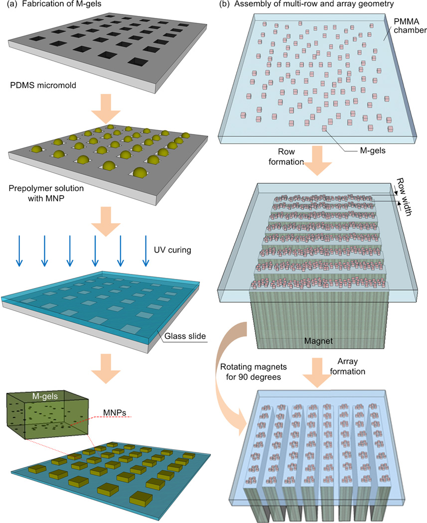
Although bioreactors for microgel assembly dependent on stirring/agitation, self-assembly [14], multi-layer photo-patterning [15] and hydrophilic-hydrophobic interactions [16] have been developed to allow 3D cellular architecture, such methods have not been broadly available in practical applications [5, 17, 18]. Since these methods have not been able to show multi-layer assembly of microgels with control, these existing assembly approaches to engineer tissues offer limited control over the 3D micro-architecture. For instance, multi-layer photo-patterning and microfluidic-directed assembly can also be used to create highly sophisticated microgel assembly architectures [19, 20], but long operational times and complex peripheral equipment are usually required. Also, photo-patterning may suffer from multiple ultraviolet light exposures to create multi-layer structures, and this method was mostly used for 2D surface patterning to achieve simple geometries [21–23]. Although the capability to fabricate microscale cell-laden hydrogels using the photo-patterning method has been shown, 3D assembly of these microgels to form larger 3D complex constructs is still a challenge. Therefore, a straightforward technology enabling 3D microgel assembly therefore remains an unmet need [5, 18]. To address these challenges, we fabricated magnetic nanoparticle (MNP) loaded cell-encapsulating microscale hydrogels (M-gels) and assembled these gels into 3D multi-layer constructs via magnetic fields (Fig. 1, Fig. S1). By spatially controlling the magnetic field, the geometry of the 3D construct can be manipulated, and multi-layer assembly of multiple microgel layers can be achieved.
Figure 1.
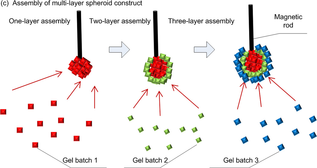
Schematic of magnetic directed assembly of microgels. (a) M-gels were fabricated via micromolding. (b) M-gels in a fluidic chamber were assembled to rows and arrays of constructs. The scattered M-gels were arranged from a random distribution to a row formation via parallel magnets separated by PMMA spacers. Then, they were assembled into an array formation by rotating the magnets by 90 degrees to the base of the chamber. (c) M-gels were assembled to fabricate three-layer spheroids through the application of external magnetic fields.
Magnetics has been exploited in a variety of direct cellular manipulation, cell sorting, 3D cell culture, local hyperthermia therapy, and clinical imaging applications [10, 24–31]. Magnetic fields have been utilized to manipulate cells to achieve 3D tissue culture leveraging magnetic levitation [32]. In this method, cells were encapsulated in a bioinorganic hydrogel composed of bacteriophage, magnetic iron oxide, and gold nanoparticles, where bacteriophage has the ligand peptide targeting the gold nanoparticles and magnetic iron oxide. Incorporation of MNPs has been employed to create 2D surface patterns [25, 33–35], form 3D cell culture arrays [36] and characterize cell-membrane mechanical properties [37]. In most of these magnetic methods, cells were first mixed directly with ferrofluid or functionalized MNPs and then exposed to external magnetic fields, allowing for controlled manipulation. Besides, methods to encapsulate MNPs in hydrogel microparticles have been developed based on microfluidics [28, 38–40] and applied to multiplexed bioassays [41, 42]. However, although MNPs have been adjusted to bind to cells, the combination of MNP-cell encapsulation in microgels and their magnetic assembly to achieve 3D multi-layer constructs has not yet been systematically applied.
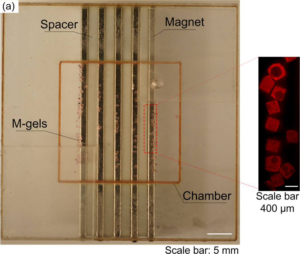
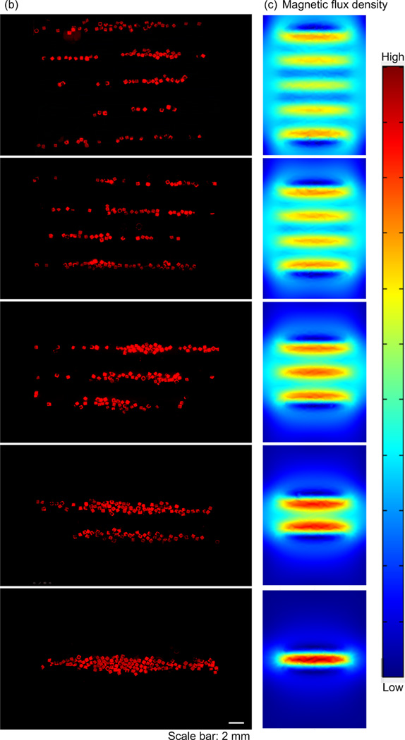
To evaluate the manipulation of M-gels via magnetic fields, we developed a magnetic assembler (Fig. 1b and Fig. S2), where M-gels were enclosed in a chamber and subjected to a magnetic field (Fig. 2a). To test the magnetic response of M-gels, we applied a magnetic field to the chamber using parallel sheet magnets (Fig. 1b). The resulting constructs assembled in a line geometry as multiple rows (Fig. 2b). To better understand this phenomenon, we performed finite element analysis of the magnetic field patterns in microgel assembler chamber. The simulation results (Fig. 2c) agreed with experimental observations (Fig. 2b). For the parallel magnets, the axes of magnetization ran parallel to the chamber surface. Magnetic field strength was greatest immediately adjacent to the magnets while the space between magnets corresponded to local minima in the magnetic field (Fig. 2c). This magnetic field led to a parallel, linear chain pattern at the onset of assembly produced by the force that attracts M-gels towards the field maximum. We observed the assembled constructs to retain their shape and remain intact after the magnets were removed (Fig. 2b). Breaks in chains (Fig. 2b) were observed when a low number of M-gels were placed into the magnetic-assembler (200 gels mL−1). The magnetic spacers (PMMA) influence the flux lines between adjacent magnets. The magnetic field is stronger and the gradient is steep in the vicinity of the outer magnets depending on the location and orientation of the magnets. In addition, when the assembler chamber size is larger than the magnet area, gels outside the magnets are drawn primarily to the outer magnetic field zones (Fig. 2b). The inner magnetic zones attract gels in their immediate vicinity. Thus, the outer magnets effectively draw gels from a larger chamber volume than the inner magnets based on the chamber design. A high concentration of gels loaded into the chamber minimized the dependency of assembled row width of the constructs on the relative positioning and magnitude of the magnetic flux density maxima and minima.
Figure 2.
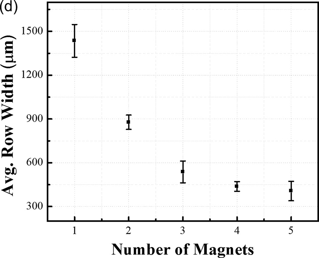
Row assembly of M-gels. (a) Magnetic assembler is shown. Fluorescence images of microgels assembled in PBS, (b) aligned using 1 to 5 magnets as compared to (c) in-channel magnetic flux density simulated using finite element analysis. (d) Effect of number of magnets on average assembled row width using the same number of microgels per chamber. Row widths from multiple constructs were averaged to obtain the mean and standard deviation for the process.
To tune row width, we assembled microgels using different numbers of magnets placed under the assembler chamber (Fig. 1b, and Fig. 2b–c). We observed that by reducing the number of magnets and holding the number of gels constant, the same number of gels was distributed among fewer magnetic field maxima (Fig. 2b). This gave wider assembled constructs. The average row width were observed as 1435 ± 113 µm, 877 ± 49 µm, 537 ± 75 µm, 438 ± 33 µm and 406 ± 67 µm for n=1, 2, 3, 4, 5 magnets, respectively (Fig. 2d). The row assembly process took less than a second (Video S1, Supporting Information) indicating rapid assembly and potential for scalability. By further rotating magnets, microgel array with uniform element size were formed (Fig. 1b, Fig. S3), and there was no significant variation in uniformity between arrays of different sizes (Fig. S3m), indicating the scalability of the platform. Besides, the assembly time for array formation via magnetic manipulation of M-gels increased with increasing array size from 2x2 to 8x8 (Fig. S3n).
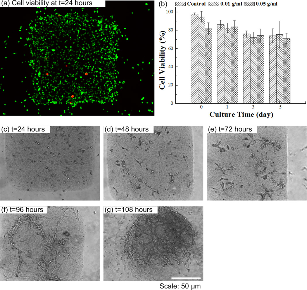
Having demonstrated the ability to manipulate M-gels, we subsequently used NIH 3T3 cells as a model to evaluate the magnetic assembler and cell viability after the assembly process steps (Fig. 3). We observed that cell viability in M-gels over 5 days, and in controls of PEG without MNPs, were comparable, Figure 3a–b. Within the initial 24 hours, the cell viabilities in both MNP M-gels and in controls were above 80%, which reached ~70% and stayed at that level at days 3 and 5. Cell viability was observed to decrease over days even in the controls, where no MNPs were encapsulated. These results agreed with earlier reports on cell viability with PEG gels [43, 44]. We also tracked the cell growth, attachment and spread in these M-gels. We observed that these cells grew, attached, spread within the gels and formed a 3D microtissue construct after 108 hours (Fig. 3c–g).
Figure 3.
Cell encapsulation in M-gels. (a) Fluorescent image of live/dead staining of 3T3 cells in M-gels at t=24 hours (green represents live cells, red represents dead cells). (b) 3T3 cell viability in M-gels was comparable to the controls over a five day culture. The cell viability was normalized to that of controls in culture flask (97.8%). Cell viability in M-gels for each day was comparable to the microgel controls without MNPs. Images of 3T3 cells in M-gels at (c) t=24 hours, (d) t=48 hours, (e) t=72 hours, (f) t=96 hours, (g) t=108 hours. The images (c-g) indicated the presence of cells in M-gels, which were observed to attach and spread within the gel as the gel biodegrades over time.
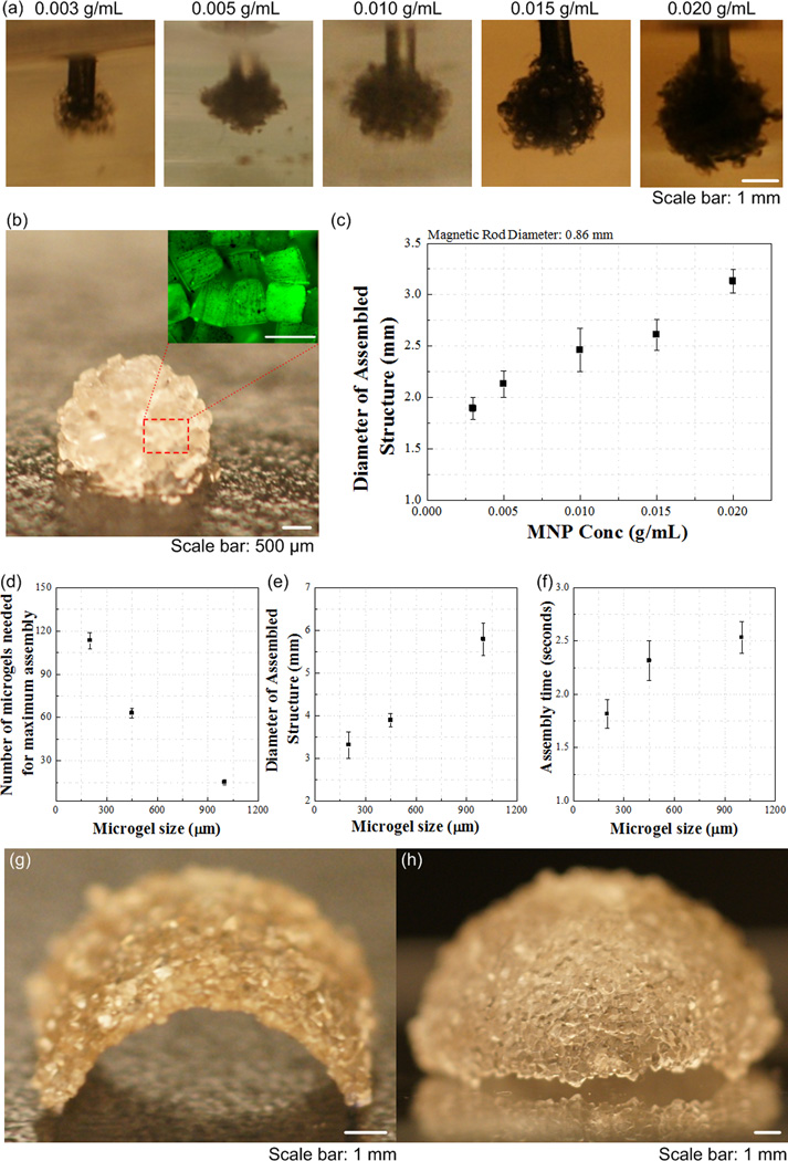
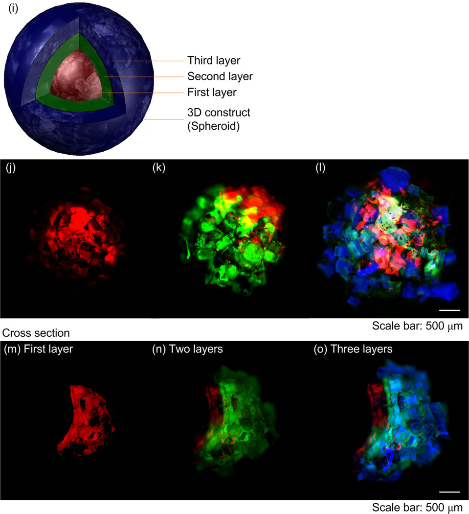
The presented approach can also provide temporal and spatial control to manipulate microgels in a 3D environment. To demonstrate this, we fabricated 3D multi-layer spherical constructs using the assembly system, in which M-gels were collected onto the tip of a magnetic rod and each layer was stabilized via second crosslinking using filling layer of PEG. Using a filling layer between multiple gels may increase the cell-cell distances, with effects on cell-cell communication. Hence, minimal gaps and maximum contact between microgels is advantageous during assembly. On the other hand, the cells in hydrogels are shown to self-assemble, migrate in the hydrogels after culture [5, 45–47]. The process took 5 seconds to assemble a 10 mm diameter 3D single-layer spheroid (Video S2, Supporting Information). By varying the MNP concentration in M-gels, single-layer spheroid assemblies of different sizes were achieved (Fig. 4a–b). The gaps remaining between microgels after assembly were filled with PEG and crosslinked to stabilize the structure, which eliminated disassembly (Fig. 4b). The maximal assembled spheroid diameters were 1.89 ± 0.11 mm, 2.13 ± 0.13 mm, 2.46 ± 0.21 mm, 2.61 ± 0.15 mm and 3.13 ± 0.11 mm at MNP concentrations of 0.003, 0.005, 0.010, 0.015, 0.020 g mL−1, respectively (Fig. 4c). To assess the effect of microgel size on assembly process, we assembled spheroid constructs using three microgel sizes (200 μm, 400 μm, 1 mm). We observed that the number of microgels needed to achieve maximum assembly size for fixed magnetic field decreased with increasing microgel size (Fig. 4d), while the diameter of assembled structure increased (Fig. 4e). Although there was difference in the assembly time for different microgel sizes (Fig. 4f), it took less than 3 seconds all the cases. Other complex constructs were also fabricated by combining magnetic field with flexible surfaces (Fig. 4g–h), such as an arc (Fig. 4g) and a dome (Fig. 4h). These geometries were chosen as examples to mimic structures observed in vivo, e.g., dome for diaphragm (dome-shaped muscle) beneath the lungs, tube for vascular structure, sphere for islets, and hexagon for lobule in pancreas. The capability to control the spheroid size via varying MNP concentration allowed fabrication of 3D multi-layer spheroids, Figure 4i–o. Such capability to assemble microgels into complex shapes (e.g., such as spherical, dome, and tube shaped gels) of multi-lamellar structures brings a unique potential to 3D assembly.
Figure 4.
Multilayer spherical assembly of M-gels. (a) Images of assembled sing-layer spheroid using five different MNP concentrations (0.003, 0.005, 0.010, 0.015, 0.020 g mL−1). (b) Magnified image of the assembled single-layer 3D construct. (c) Maximum 3D assembly size as a function of MNP concentration. The effect of microgel size on (d) number of microgels needed for achieving maximum assembly size, (e) diameter of assembled structure, and (f) corresponding assembly time. (g)-(h) Images of fabricated arc and dome shaped constructs using a flexible surface and magnetic assembly. (i)-(o) Merged fluorescent images of three-layer spheroids. First layer gels were stained with rhodamine-B (j); second layer gels were stained with FITC-dextran (k); third layer gels were stained with TPB (1,1,4,4-Tetraphenyl-1,3-butadiene) (l). (m)-(o) The cross sections of the layers by cutting the assembled construct into two hemispheres. The images were merged showing all three layers.
Hydrogels are 3D cross-linked networks of polymers that feature advantageous biological properties, including moldability, high porosity and diffusion controllability, resembling the physical characteristics of native cell microenvironment [48]. We have used two types of hydrogels to create M-gels for the assembly process, i.e., GelMA and PEG. GelMA is biodegradable and PEG gels can be modified to become biodegradable. Although PEG is not biodegradable and cells may not come in direct contact with cells from other gels, PEG can be functionalized with functional groups for various applications, such as for controlled differentiation of human mesenchymal stem cells encapsulated in PEG based hydrogels [49]. The PEG can also be modified to become biodegradable [50, 51]. In addition, the magnetic assembly method reported here is not limited to PEG and could be extended to other hydrogels such as Agarose, GelMA, PELGA. Since the assembly process is determined by the interaction of the magnetic particles in the M-gel with the magnetic field, we did not observe any differences in the assembly process of the degradable and biodegradable gels. Further, cells are reported to self-assemble and migrate in 3D hydrogels in vitro in various hydrogels such as collagen, matrigel and fibrinogen [5, 21, 45–47, 52]. These studies not only show that cells can migrate in 3D hydrogel matrix, but also that the migration behavior in 3D is different from that on 2D surfaces [45]. For instance, the maximum migration speed of human prostate carcinoma cells on 2D substrates and 3D substrates are different, and depends on the mechanical properties of the matrix [46].
Incorporation of MNPs into microgels creates a new biomaterial that maintains the biocompatibility of hydrogels [53, 54], while contributing additional capabilities for culture, magnetic manipulation, and complex 3D assembly of microgels. The United States Food and Drug Administration (FDA) has approved the use of MNPs in several applications such as imaging agents [55], and tolerability of mammalian cells to MNPs have been demonstrated under used conditions [33, 34, 56]. Besides, MNPs do not need to stay for long times within the assembled constructs and they can be released out as the gels biodegrade, and cells secrete their own ECM and take over the space. Therefore, magnetic directed assembly of microgels may become a practical biotechnological tool. Although MNPs are used clinically, further toxicological studies would be beneficial for other types of applications including 3D microgel assembly.
The technology presented here offers an alternative to top-down biodegradable scaffold approaches [57–59], which face cell seeding limitations due to slow propagation of cells and delayed establishment of cell–cell interactions. On the other hand, MNP-based microgel assembly allows adaptable manipulation of microgels and has the potential to provide improved 3D architecture and microenvironment for cell-growth predetermined by the assembly design and microgel composition. This method is cost-effective, since it does not require specific peripheral equipment, and is compatible with standard cell culture and hydrogel techniques. The magnetic-driven assembly offers several advantages over existing methods including self-assembly. The assembly time by the existing assembly methods are within the order of tens of minutes without considering the time for the chemical manipulation of microgels, where they are exposed to potentially toxic chemicals. In contrast, the magnetic approach is rapid (~seconds) without these lengthy preprocessing steps and MNPs are regularly mixed as a part of the microgel with the cells. Besides, the existing assembly methods provide no control over the 3D assembly process where any microgel can end up being assembled at a specific location. The magnetic field can be extrapolated to assemble microgels with spatial control. Although we have not used focused magnetic fields in this paper to control a single microgel, this technology in principle enables this level of control as shown by earlier work on the magnetic control of a nanoneedle in the retina [60], indicating a significant improvement over the existing assembly methods. Even the directed assembly methods that use hydrophobicity and hydrophilicity [61] do not assemble a single gel with control to a specified location in 3D. Furthermore, the existing methods have shown assembly mostly in 2D where gels come together randomly. Here, we present assembly in the 3D where microgels are not only coming to side-by-side but assembling around a field in all directions controlled by the magnetic field strength and interference. Although the earlier work on microgel assembly in 2D is intriguing, these assembled gels are now larger in size and need to further be assembled to build even larger and physiologically relevant complex structures that could be useful for tissue engineering applications. To build such larger constructs, the scalability of the assembly mechanisms of existing methods has not been demonstrated. The magnetic assembly method presents a large scale assembly with control over multiple layers of gels rapidly by using a simplistic approach, where existing assembly methods mostly have not gone beyond the assembly of few gels next to each other in 2D repeatably. For instance, the magnetic method can create multi-lamellar (i.e., multi-layer) 3D constructs of complex shapes repeatably using the same MNP concentration levels, and assemble different layer thicknesses by changing these concentrations. The magnetic manipulation of M-gels into microarrays poses a scalable method, as indicated by the above results on chamber sizes, assembly times and distribution of gel numbers. Although we only presented up to an 8x8 array formation in this study, the method is shown to be scalable without significantly increasing assembly times. We envision that for a large-scale process, the 8x8 microarray contained within an area of 5 cm×5 cm can be placed into microfluidic systems merged with the proposed magnetic assembly approach. The combination would enable a small array (i.e., 8x8 array) to be assembled, screened, and dispersed quickly. In this sense, the magnetic-driven assembly is a major step beyond the existing assembly methods and is a unique approach to tissue assembly.
It is important to notice that there are also limitations on the maximum amplitude for the local magnetic field for the 3D assembly. High levels of magnetic force induced may shear the gels and can influence the microgel integrity. In this study, low intensity magnetic fields yielded assembly of these MNP encapsulating microgels. There are limitations on the amplitude and duration of the magnetic fields that can be used. The use of alternative current-based (AC) magnetic fields may lead to a certain amount of heat (magnetic hyperthermia) that may counter-act the process of magnetic assembly. Since the assembly was performed in several seconds using permanent magnets, we didn’t observe such adverse affects, however, these design parameters need to be considered for larger scale constructs. We also expect that the shape of the microgels will affect assembly process, where more complex shapes such as saw, lock-key actually makes it harder to assemble these gels in controlled geometries. Since agglomeration of MNPs is known to occur in prepolymer solutions [62, 63], there exists a possibility that the MNP distribution is not the same in each M-gel. Thus, some M-gels could have a lower affinity to the magnetic field. Hence, pre-filtering and sonication of MNPs could minimize non-uniformities from the process steps. Another challenge with this method is that some of the M-gels did not remain on the chamber floor, but floated to the surface of the PBS, which can be solved by adding more PBS to settle these floating M-gels. Another solution is using microfluidic channels to refrain from such challenges that may be related to the surface tension of the fluids that the gels reside in during assembly.
This study indicates that the developed methodology can potentially become a complementary and simpler surrogate for engineering multilayer 3D constructs. The magnetic assembler reported here has potential to impact multiple fields including tissue engineering and regenerative medicine, pharmacology, and stem cell research.
Supplementary Material
Acknowledgements
This work was performed at the Demirci Bio-Acoustic MEMS in Medicine (BAMM) Laboratories at the Harvard-Massachusetts Institute of Technology Health Sciences and Technology (HST), Center for Bioengineering at Brigham and Women’s Hospital, Harvard Medical School. The authors would thank Imran Khimji for helpful discussions. This work was partially supported by NIH R21 (EB007707). We thank the MIT Deshpande Center Award, W.H. Coulter Foundation Young Investigator Award, NIH R01 (AI081534), NIH R21 (AI087107), and Integration of Medicine and Innovative Technology (CIMIT) under U.S. Army Medical Research Acquisition Activity Cooperative Agreement, as well as made possible by a research grant that was awarded and administered by the U.S. Army Medical Research & Materiel Command (USAMRMC) and the Telemedicine & Advanced Technology Research Center (TATRC), at Fort Detrick, MD.
Footnotes
Supporting Information
Supporting Information is available from the Wiley Online Library or from the author.
REFERENCES
- 1.Nichol JW, Khademhosseini A. Soft Matter. 2009;5:1312. doi: 10.1039/b814285h. [DOI] [PMC free article] [PubMed] [Google Scholar]
- 2.Perez-Castillejos R. Materials Today. 13:32. [Google Scholar]
- 3.Langer R, Vacanti JP. Science. 1993;260:920. doi: 10.1126/science.8493529. [DOI] [PubMed] [Google Scholar]
- 4.Davenport RJ. Science. 2005;309:84. doi: 10.1126/science.309.5731.84. [DOI] [PubMed] [Google Scholar]
- 5.Griffith LG, Swartz MA. Nature reviews. 2006;7:211. doi: 10.1038/nrm1858. [DOI] [PubMed] [Google Scholar]
- 6.Song YS, Lin RL, Montesano G, Durmus NG, Lee G, Yoo SS, Kayaalp E, Haeggstrom E, Khademhosseini A, Demirci U. Anal Bioanal Chem. 2009;395:185. doi: 10.1007/s00216-009-2935-1. [DOI] [PubMed] [Google Scholar]
- 7.Xu F, Celli J, Rizvi I, Moon S, Hasan T, Demirci U. Biotechnology Journal. 2011;6:204. doi: 10.1002/biot.201000340. [DOI] [PMC free article] [PubMed] [Google Scholar]
- 8.Yamada KM, Cukierman E. Cell. 2007;130:601. doi: 10.1016/j.cell.2007.08.006. [DOI] [PubMed] [Google Scholar]
- 9.Hutmacher DW. Nat Mater. 2010;9:90. doi: 10.1038/nmat2619. [DOI] [PubMed] [Google Scholar]
- 10.Souza GR, Molina JR, Raphael RM, Ozawa MG, Stark DJ, Levin CS, Bronk LF, Ananta JS, Mandelin J, Georgescu MM, Bankson JA, Gelovani JG, Killian TC, Arap W, Pasqualini R. Nature nanotechnology. 2010;5:291. doi: 10.1038/nnano.2010.23. [DOI] [PMC free article] [PubMed] [Google Scholar]
- 11.Xu F, Moon S, Emre AE, Turali ES, Song YS, Hacking A, Nagatomi, Demirci U. Biofabrication. 2010 doi: 10.1088/1758-5082/2/1/014105. [DOI] [PubMed] [Google Scholar]
- 12.Du Y, Lo E, Ali S, Khademhosseini A. Proc Natl Acad Sci U S A. 2008;105:9522. doi: 10.1073/pnas.0801866105. [DOI] [PMC free article] [PubMed] [Google Scholar]
- 13.Moon S, Hasan SK, Song YS, Xu F, Keles HO, Manzur F, Mikkilineni S, Hong JW, Nagatomi J, Haeggstrom E, Khademhosseini A, Demirci U. Tissue Eng Part C Methods. 2010;16:157. doi: 10.1089/ten.TEC.2009.0179. [DOI] [PMC free article] [PubMed] [Google Scholar]
- 14.McGuigan AP, Leung B, Sefton MV. Nat Protoc. 2006;1:2963. doi: 10.1038/nprot.2006.443. [DOI] [PubMed] [Google Scholar]
- 15.Liu Tsang V, Chen AA, Cho LM, Jadin KD, Sah RL, DeLong S, West JL, Bhatia SN. FASEB J. 2007;21:790. doi: 10.1096/fj.06-7117com. [DOI] [PubMed] [Google Scholar]
- 16.Zamanian B, Masaeli M, Nichol JW, Khabiry M, Hancock MJ, Bae H, Khademhosseini A. Small. 2010;6:937. doi: 10.1002/smll.200902326. [DOI] [PMC free article] [PubMed] [Google Scholar]
- 17.Abbott A. Nature. 2003;424:870. doi: 10.1038/424870a. [DOI] [PubMed] [Google Scholar]
- 18.Pampaloni F, Reynaud EG, Stelzer EHK. Nature reviews. 2007;8:839. doi: 10.1038/nrm2236. [DOI] [PubMed] [Google Scholar]
- 19.Bryant SJ, Cuy JL, Hauch KD, Ratner BD. Biomaterials. 2007;28:2978. doi: 10.1016/j.biomaterials.2006.11.033. [DOI] [PMC free article] [PubMed] [Google Scholar]
- 20.Hahn MS, Taite LJ, Moon JJ, Rowland MC, Ruffino KA, West JL. Biomaterials. 2006;27:2519. doi: 10.1016/j.biomaterials.2005.11.045. [DOI] [PubMed] [Google Scholar]
- 21.Lee SH, Moon JJ, West JL. Biomaterials. 2008;29:2962. doi: 10.1016/j.biomaterials.2008.04.004. [DOI] [PMC free article] [PubMed] [Google Scholar]
- 22.Mercey E, Obeid P, Glaise D, Calvo-Munoz ML, Guguen-Guillouzo C, Fouque B. Biomaterials. 2010;31:3156. doi: 10.1016/j.biomaterials.2010.01.020. [DOI] [PubMed] [Google Scholar]
- 23.Bassik N, Abebe BT, Laflin KE, Gracias DH. Polymer. 2010;51:6093. [Google Scholar]
- 24.Kose AR, Fischer B, Mao L, Koser H. Proc Natl Acad Sci U S A. 2009;106:21478. doi: 10.1073/pnas.0912138106. [DOI] [PMC free article] [PubMed] [Google Scholar]
- 25.Krebs MD, Erb RM, Yellen BB, Samanta B, Bajaj A, Rotello VM, Alsberg E. Nano Lett. 2009;9:1812. doi: 10.1021/nl803757u. [DOI] [PMC free article] [PubMed] [Google Scholar]
- 26.Frasca G, Gazeau F, Wilhelm C. Langmuir. 2009;25:2348. doi: 10.1021/la8030792. [DOI] [PubMed] [Google Scholar]
- 27.Yellen BB, Hovorka O, Friedman G. Proc Natl Acad Sci U S A. 2005;102:8860. doi: 10.1073/pnas.0500409102. [DOI] [PMC free article] [PubMed] [Google Scholar]
- 28.Chen C-H, Abate AR, Lee D, Terentjev EM, Weitz DA. Advanced Materials. 2009;21:3201. [Google Scholar]
- 29.Pankhurst Q, Connolly J, Jones SK, Dobson J. J. Phys. D. 2003;36:R167. [Google Scholar]
- 30.Alsberg E, Feinstein E, Joy MP, Prentiss M, Ingber DE. Tissue Eng. 2006;12:3247. doi: 10.1089/ten.2006.12.3247. [DOI] [PubMed] [Google Scholar]
- 31.Le Renard PE, Jordan O, Faes A, Petri-Fink A, Hofmann H, Rufenacht D, Bosman F, Buchegger F, Doelker E. Biomaterials. 2010;31:691. doi: 10.1016/j.biomaterials.2009.09.091. [DOI] [PubMed] [Google Scholar]
- 32.Coleman CB, Gonzalez-Villalobos RA, Allen PL, Johanson K, Guevorkian K, Valles JM, Hammond TG. Biotechnol Bioeng. 2007;98:854. doi: 10.1002/bit.21526. [DOI] [PubMed] [Google Scholar]
- 33.Dobson J. Nature nanotechnology. 2008;3:139. doi: 10.1038/nnano.2008.39. [DOI] [PubMed] [Google Scholar]
- 34.Ito A, Ino K, Kobayashi T, Honda H. Biomaterials. 2005;26:6185. doi: 10.1016/j.biomaterials.2005.03.039. [DOI] [PubMed] [Google Scholar]
- 35.Akiyama H, Ito A, Kawabe Y, Kamihira M. Biomedical microdevices. 2009;11:713. doi: 10.1007/s10544-009-9284-x. [DOI] [PubMed] [Google Scholar]
- 36.Okochi M, Takano S, Isaji Y, Senga T, Hamaguchi M, Honda H. Lab on a Chip. 2009;9:3378. doi: 10.1039/b909304d. [DOI] [PubMed] [Google Scholar]
- 37.Meyer CJ, Alenghat FJ, Rim P, Fong JH-J, Fabry B, Ingber DE. Nat Cell Biol. 2000;2:666. doi: 10.1038/35023621. [DOI] [PubMed] [Google Scholar]
- 38.Hwang DK, Dendukuri D, Doyle PS. Lab Chip. 2008;8:1640. doi: 10.1039/b805176c. [DOI] [PubMed] [Google Scholar]
- 39.Pregibon DC, Toner M, Doyle PS. Langmuir. 2006;22:5122. doi: 10.1021/la0534625. [DOI] [PubMed] [Google Scholar]
- 40.Yuet KP, Hwang DK, Haghgooie R, Doyle PS. Langmuir. 2009 doi: 10.1021/la903348s. [DOI] [PubMed] [Google Scholar]
- 41.Lee H, Kim J, Kim H, Kwon S. Nat Mater. 2010;9:745. doi: 10.1038/nmat2815. [DOI] [PubMed] [Google Scholar]
- 42.Bong KW, Chapin SC, Doyle PS. Langmuir. 2010;26:8008. doi: 10.1021/la904903g. [DOI] [PMC free article] [PubMed] [Google Scholar]
- 43.Burdick JA, Anseth KS. Biomaterials. 2002;23:4315. doi: 10.1016/s0142-9612(02)00176-x. [DOI] [PubMed] [Google Scholar]
- 44.Nuttelman CR, Tripodi MC, Anseth KS. Journal of biomedical materials research. 2004;68:773. doi: 10.1002/jbm.a.20112. [DOI] [PubMed] [Google Scholar]
- 45.Fraley SI, Feng Y, Krishnamurthy R, Kim DH, Celedon A, Longmore GD, Wirtz D. Nat Cell Biol. 2010;12:598. doi: 10.1038/ncb2062. [DOI] [PMC free article] [PubMed] [Google Scholar]
- 46.Zaman MH, Trapani LM, Sieminski AL, MacKellar D, Gong H, Kamm RD, Wells A, Lauffenburger DA, Matsudaira P. Proceedings of the National Academy of Sciences. 2006;103:10889. doi: 10.1073/pnas.0604460103. [DOI] [PMC free article] [PubMed] [Google Scholar]
- 47.Luo Y, Shoichet MS. Nat Mater. 2004;3:249. doi: 10.1038/nmat1092. [DOI] [PubMed] [Google Scholar]
- 48.Geckil H, Xu F, Zhang X, Moon S, Demirci U. Nanomedicine (Lond) 2010;5:469. doi: 10.2217/nnm.10.12. [DOI] [PMC free article] [PubMed] [Google Scholar]
- 49.Benoit DS, Schwartz MP, Durney AR, Anseth KS. Nat Mater. 2008;7:816. doi: 10.1038/nmat2269. [DOI] [PMC free article] [PubMed] [Google Scholar]
- 50.Kloxin AM, Tibbitt MW, Anseth KS. Nat. Protocols. 2010;5:1867. doi: 10.1038/nprot.2010.139. [DOI] [PMC free article] [PubMed] [Google Scholar]
- 51.Kloxin AM, Kasko AM, Salinas CN, Anseth KS. Science. 2009;324:59. doi: 10.1126/science.1169494. [DOI] [PMC free article] [PubMed] [Google Scholar]
- 52.Friedl P, Wolf K. Nat Rev Cancer. 2003;3:362. doi: 10.1038/nrc1075. [DOI] [PubMed] [Google Scholar]
- 53.Souza GR, Christianson DR, Staquicini FI, Ozawa MG, Snyder EY, Sidman RL, Miller JH, Arap W, Pasqualini R. Proceedings of the National Academy of Sciences of the United States of America. 2006;103:1215. doi: 10.1073/pnas.0509739103. [DOI] [PMC free article] [PubMed] [Google Scholar]
- 54.Souza GR, Yonel-Gumruk E, Fan D, Easley J, Rangel R, Guzman-Rojas L, Miller JH, Arap W, Pasqualini R. PLoS One. 2008;3:e2242. doi: 10.1371/journal.pone.0002242. [DOI] [PMC free article] [PubMed] [Google Scholar]
- 55.LaConte L, Nitin N, Bao G. Materials Today. 2005;8:32. [Google Scholar]
- 56.Hautot D, Pankhurst QA, Morris CM, Curtis A, Burn J, Dobson J. Biochim Biophys Acta. 2007;1772:21. doi: 10.1016/j.bbadis.2006.09.011. [DOI] [PMC free article] [PubMed] [Google Scholar]
- 57.Mikos AG. Tissue Eng. 2006;12:3307. doi: 10.1089/ten.2006.12.3307. [DOI] [PMC free article] [PubMed] [Google Scholar]
- 58.Choi NW, Cabodi M, Held B, Gleghorn JP, Bonassar LJ, Stroock AD. Nat Mater. 2007;6:908. doi: 10.1038/nmat2022. [DOI] [PubMed] [Google Scholar]
- 59.Hollister SJ. Nat Mater. 2005;4:518. doi: 10.1038/nmat1421. [DOI] [PubMed] [Google Scholar]
- 60.Nelson BJ, Kaliakatsos IK, Abbott JJ. Annu Rev Biomed Eng. 2010;12:55. doi: 10.1146/annurev-bioeng-010510-103409. [DOI] [PubMed] [Google Scholar]
- 61.Fernandez JG, Khademhosseini A. Advanced Materials. 2010;9999 doi: 10.1002/adma.200903893. NA. [DOI] [PMC free article] [PubMed] [Google Scholar]
- 62.Wang Y, Li B, Zhou Y, Jia D. Polymers for Advanced Technologies. 2008;19:1256. [Google Scholar]
- 63.Xia H-B, Yi J, Foo P-S, Liu B. Chemistry of Materials. 2007;19:4087. [Google Scholar]
Associated Data
This section collects any data citations, data availability statements, or supplementary materials included in this article.


