Abstract
Embryonic heart valves develop under continuous and demanding hemodynamic loading. The particular contributions of fluid pressure and shear tractions in valve morphogenesis are difficult to decouple experimentally. To better understand how fluid loads could direct valve formation, we developed a computational model of avian embryonic atrioventricular (AV) valve (cushion) growth and remodeling using experimentally derived parameters for the blood flow and the cushion stiffness. Through an iterative scheme, we first solved the fluid loads on the axisymmetric AV canal and cushion model geometry. We then applied the fluid loads to the cushion and integrated the evolution equations to determine the growth and remodeling. After a set time of growth, we updated the fluid domain to reflect the change in cushion geometry and re-solved for the fluid forces. The rate of growth and remodeling was assumed to be a function of the difference between the current stress and an isotropic homeostatic stress state. The magnitude of the homeostatic stress modulated the rate of volume addition during the evolution. We found that the pressure distribution on the AV cushion was sufficient to generate leaflet-like elongation in the direction of flow, through inducing tissue resorption on the inflow side of cushion and expansion on the outflow side. Conversely, shear tractions minimally altered tissue volume, but regulated the remodeling of tissue near the cushion surface, particular at the leading edge. Significant shear and circumferential residual stresses developed as the cushion evolved. This model offers insight into how natural and perturbed mechanical environments may direct AV valvulogenesis, and provides an initial framework on which to incorporate more mechano-biological details.
Keywords: growth and remodeling, morphomechanics, morphogenesis, cushion, residual stress, hemodynamic loads, mechanical environment
1 Introduction
Atrioventricular valve formation is thought to be regulated by dynamic interactions between molecular and mechanical signaling. The primitive valves (cushions) initiate as gelatinous masses of hyluronan from the myocardial wall of the heart tube. A layer of endothelial cells line the inner surface of the heart tube, with the outer wall consisting of cardiomyocytes (Gonzalez-Sanchez and Bader, 1990). In a highly coordinated process, the endothelial cells lining the cushion invade the underlying matrix and acquire a mesenchymal phenotype (see illustrated reviews (Person et al., 2005; Schroeder et al., 2003; Butcher and Markwald, 2007)). As the cushion matures, these mesenchymal cells remodel the matrix directing a transition from hyluronan to collagen based matrix, and a transition from globular to planar morphology (Kruithof et al., 2007; Hinton et al., 2006). Significant advances have been made in identifying the key molecular signals needed for this initiation and maturation (Butcher and Markwald, 2007; Eisenberg and Markwald, 1995; Person et al., 2005), yet little is known about the role of mechanical signaling in cushion development. The hemodynamic environment of the embryonic cushion rapidly increases in pressure over development, resulting in an exponential increase in cardiac output and heightened wall shear stresses (Hu and Clark, 1989; Yalcin et al., 2011). Concomitant with this increase in mechanical load, the AV cushions elongate to form thin, fibrous leaflets with increased extracellular matrix (ECM) proteins and greater mechanical stiffness (Buskohl et al., 2012; Butcher et al., 2007; Kruithof et al., 2007).
These findings motivate the hypothesis that hemodynamic forces direct valve morphology and stimulate the turnover and remodeling of the internal valve constituents. Surgical manipulations of heart development have demonstrated that alteration of hemodynamic flows result in altered cardiac morphology(Hogers et al., 1997; Vermot et al., 2009), which correlates with differences in local shear stress profiles (Hove et al., 2003; Groenendijk et al., 2005), pressure (Sedmera et al., 1999), and myocardial activity (Bartman et al., 2004). It is not yet known whether pressure gradients or wall shear stress could drive AV valve morphogenesis, but directly uncoupling the effects of pressure and shear tractions are impossible to do in vivo. Without this understanding, prediction of AV cushion morphology in altered hemodynamic environments is limited.
Computational approaches to the study of the mechanical regulation of morphogenesis are an attractive alternative to address these issues of coupled loading and predictability. Numerical models have provided insights into the fluid dynamics of the embryonic heart, such as the transition of peristaltic to pulsatile flow (Taber et al., 2007) and the distribution of normal and shear forces in AV canal (Biechler et al., 2010; Miller, 2011). Recent gains in fluorescent and ultrasound imaging have enhanced these computational studies by providing critical information on the magnitude and temporal nature of in vivo hemodynamic loads (Forouhar et al., 2006; Hove et al., 2003; Yalcin et al., 2011). Previous stress-driven growth models have qualitatively captured the morphology of several developmental phenomenona such as invagination (Munoz et al., 2010), gastrulation (Taber, 2008, 2009), cardiac looping (Ramasubramanian et al., 2008), and ventricle growth (Lin and Taber, 1995). Stress-based growth laws assume that tissue morphology is a direct response to the current stress state, or to the difference in current stress from a homeostatic stress state. This is in contrast to growth models phrased in terms of strain or strain energy, with corresponding homeostatic states assumed as functions of these quantities (Cowin and Buskirk, 1979). Experimental evidence in plants and embryos supports stress as the mechanical criterion to which living organisms respond (Beloussov and Luchinskaia, 1995; Beloussov and Grabovsky, 2006). Stress-based evolution equations for growth also arise naturally when the entropy inequality is employed (Ambrosi and Guillou, 2007; Garikipati et al., 2004), further supporting this form of growth law.
The objective of this study was to develop and implement a computational framework incorporating both fluid-structure interaction and growth mechanics to identify mechanical mechanisms sufficient to reproduce valve-like morphology. Physiological fluid flow parameters and cushion material properties were utilized. The results indicate that fluid pressure directs spatially dependant volume addition and removal resulting in valve elongation. Shear tractions do not significantly alter volume, but instead stimulate tissue distortion, particularly near the cushion surface. Growth and remodeling induces residual stresses which may significantly alter (or guide) cushion formation over time. This model provides an initial framework of mechanically induced valve development on which further biological detail may be incorporated.
2 Methods
2.1 Kinematics
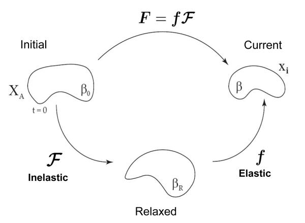
Consider a stress-free body in the reference configuration at t = 0, denoted as the initial configuration β0 in Fig. 1. The body undergoes a combined elastic-inelastic deformation from the initial to current configuration (β) defined by the mapping x = x(X, t). The observable, total deformation, , includes components of growth, remodeling and elastic deformation. We assume F can be expressed as a multiplicative decomposition of the elastic components and growth and remodeling (inelastic) components as done in several preceding works (Rodriguez et al., 1994; Lubarda and Hoger, 2002; Ramasubramanian and Taber, 2008). The total deformation is thereby defined as the product of the inelastic, , and the elastic, f, deformations.
| (1) |
The elastic deformation is considered nearly incompressible, det(f) ≈ 1, and is the deformation used to calculate the elastic stress. The inelastic deformation comprises both volumetric changes representative of growth and shape changes representative of remodeling. This deformation will be prescribed through a constituitive relation. Although the inelastic deformation does not formally contribute to the elastic stress, the geometric incompatibilities from differential growth and remodeling induce elastic residual stresses required to maintain material continuity.
Fig. 1.
Multiplicative decomposition of the deformation gradient. The observable deformation, F, is decomposed into an elastic, f, and inelastic, , deformation. All volume change occurs through as the elastic deformation is assumed to be isochoric, det(f) = 1. All growth and remodeling is described by the inelastic deformation. The initial, relaxed, and current bodies are referred to as β0, βR, and β, respectively.
2.2 Material Law
The material properties of the avian AV cushions have previously been characterized by fitting an isotropic, exponential hyperelastic material law (Eq. 2) to experimental data (Buskohl et al., 2012).
| (2) |
Parameters C and α are the linear and nonlinear material constants, respectively, of the material law, while D is inversely related to the bulk modulus which enforces the incompressibility constraint. I1 is the first invariant of the left Cauchy-Green stretch tensor b = ffT, and J = det(f) is the Jacobian of the elastic deformation. From the strain energy function (Eq. 2), the Cauchy stress is derived as
| (3) |
| (4) |
Using the pipette aspiration technique, Buskohl et al. (2012) quantified the stiffness of HH25, HH29 and HH34 AV cushions and presented the data in terms of strain energy density. The strain energy density was defined as the area under the stress-stretch ratio curve of a uni-axial loaded bar from λ = [1, 2], with closed form expression shown in Eq. 5.
| (5) |
Buskohl et al. (2012) reported significantly stiffer material properties in the plane of the tissue versus that in the trans-planar direction at HH36, indicating the development of material aniostropy. As the pipette data for HH29 cushion was likely underestimating the cushion stiffness, we attempted to compensate for this by increasing the linear stiffness parameter, C = 100 Pa. The nonlinear parameter, α = 0.3, at HH29 was retained, resulting in a strain energy density of Wavg = 41 Pa, (Table 1).
Table 1.
Fluid/Solid Material Parameters
| Item | Value | Units |
|---|---|---|
| Density | 1060 | |
| Viscosity | 0.003 | [Pa – s] |
| R | 0.5 | mm |
| Re | 5 | – |
| α | 0.3 | – |
| C | 100 | Pa |
| D | 2 E-03 | Pa−1 |
| W12 | 41 | Pa |
| a0 | 1 E-02 |
2.3 Growth Law
In this growth model, the Cauchy stress is assumed to be the key driver of the growth and remodeling processes. The deformation rate of the inelastic tensor, , is prescribed through the constituitive relation,
| (6) |
where σ* is the homeostatic stress state and a is the radially dependent growth rate parameter. The concept of a homeostatic, or target stress, has been employed in several other growth models (Rodriguez et al., 1994; Humphrey and Rajagopal, 2003; Ramasubramanian and Taber, 2008). The homeostatic stress provides a non-zero stress state at which no growth occurs. In light of limited experimental data, we assumed the homeostatic stress to be a homogeneous, isotropic compressive stress of magnitude p, (Eq. 7).
| (7) |
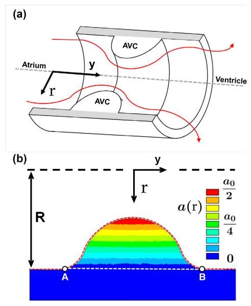
A compressive homeostatic state was chosen because the hemodynamic loads on the AV cushion are compressive. An isotropic stress state was chosen to eliminate a potential directional bias if distortional components were included. The growth rate parameter was assumed to vary linearly in the radial direction of AV canal, promoting more growth near the surface of the cushion. This was motivated by the increased cell density near the cushion surface observed from hematoxylin stained histology sections of HH27 AV valves (Fig. S1). The exact formulation used in finite element (FE) implementation was
where R is the radius of the AV canal (R=0.5 mm), and r the radial position from the axis of symmetry. A color map of the growth rate parameter is presented in Fig. 2b.
Fig. 2.
AV canal model geometry and growth rate gradient. a) Cross-section of the AV canal model geometry with AV cushions (AVC) shown inside. The red lines indicate blood flood from the atrium to the ventricle. b) Color map of growth rate parameter a(r) over the 2D AVC cross-section. R is the radias of the AV canal and r is the radial coordinate as referenced from the axis of symmetry. The dashed red line from A to B denotes the cushion surface normalized from 0 to 1 in future figures. The AVC cross-sectional area is the area bounded by the red and white dashed lines. a0 = 0.01 [Pa t]−1
2.4 FE Implementation of the Fluid/Solid Model
The mechanical environment of the AV cushion is primarily defined by the hemodynamic forces generated through the pump action of the embryonic heart. To approximate these fluid loads, the AV canal and cushion were modeled together through an idealized axisymmetric geometry (Fig. 2a). A cylindrical coordinate system was defined with the axial direction, y, oriented in the direction of flow and the radial direction, r, orthogonal to the axis of symmetry (Fig. 2). The length to diameter ratio of the AV canal was 4 mm to 1 mm and the cushion was a near semi-circular cap of radius 0.25 mm. These dimension are supported by micro-CT images of AV canals (Yalcin et al., 2011) and a previously implemented computational model of AV canal blood flow (Biechler et al., 2010). The surface of the cushion and myocardial wall interface was smoothed to mitigate potential stress concentrations. The blood was simulated as an incompressible, Newtonian fluid, with density and viscosity of 1060 kg/m3 and 0.003 Pa-s, respectively. Although blood is non-Newtonian, the viscosity is nearly constant in the range of shear rates used in our simulation (Al-Roubaie et al., 2011).
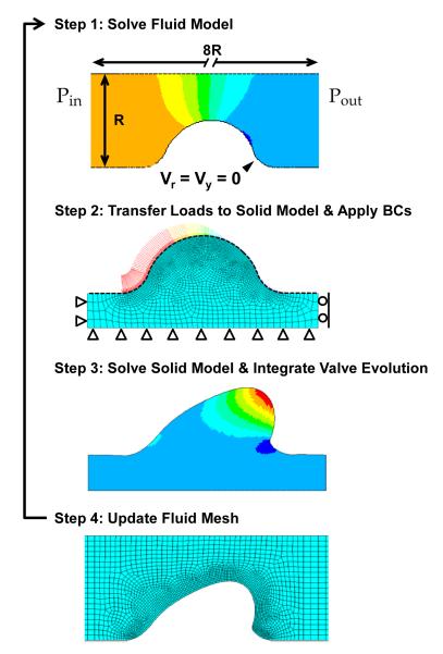
The pressure and velocity profiles were determined using the axisymmetric Navier Stokes equations for the conservation of momentum and the continuity equation. All interior surfaces of the canal, including the cushions, had no slip boundary conditions (Fig. 3 Step 1). The inflow and outflow pressures were selected to match experimental data of the time averaged velocity through the AV orifice (3.08 cm/s ± 0.99 cm/s, Yalcin et al. 2011). The time-averaged velocity was calculated by averaging AV orifice velocities over one cardiac cycle, or heartbeat. This is the mean loading velocity experienced by the cushion, and was considered a reasonable approximation of the loading range which directs cushion growth.
Fig. 3.
Schematic of fluid/solid interaction algorithm and boundary conditions (BC). Each iteration followed this process, Step 1: Simulate the fluid flow in the AV canal with no slip velocity BCs along the fluid/solid interface and a pressure drop, ΔP = Pin - Pout, across the canal. Step 2: Transfer the pressure and wall shear stress loads from the fluid model to the cushion surface using the 1D surface elements (black dashed line). Apply displacement BCs to myocardium as shown. Step 3: Calculate the elastic stress and inelastic deformation for a set time of growth and remodeling, and then remove load. Step 4: Update the fluid mesh using the new relaxed cushion geometry. Repeat Steps 1-4.
The peak velocity blood flow was simulated to compare the AV orifice velocities profiles from the experimental data and our model. This comparison was only used to validate our idealized geometry for the AV canal and cushion. The pressure drop across the AV canal necessary to match the AV orifice velocity for the average and peak flow conditions was 62 and 1200 dynes/cm2, respectively. Reynolds numbers for each condition were Re = 5 and Re = 65 using the AV orifice diameter (0.5mm) as the characteristic length.
The fluid/solid model was decoupled in the FE implementation, and solved through a semi-iterative approach. First the pressure and velocity profiles were determined from the fluid problem. The flow-induced pressure and shear tractions on the AV cushion surface were then transferred to the solid model to simulate the elastic and inelastic deformations. After a set time of inelastic deformation, the fluid simulation was rerun with the evolved geometry, and the fluid forces were updated (see Fig. 3).
The FE simulations were computed in ANSYS v12.1 using four-node quadrilateral elements in both the fluid and solid domains (meshes are shown in Fig. 3). A series of two-node surface elements were used to transfer the normal and shear components of the fluid load onto the solid model (black dashed line in Fig. 3 step 2). A total of 3400 fluid elements and 2400 solid elements were used in the simulations. The exponential material law and the growth law were implemented through the USERMAT subroutine. At every integration point, the USERMAT subroutine would determine the elastic deformation gradient and calculate the Cauchy stress and the spatial elasticity tensor. The growth tensor would also be updated through the following explicit integration scheme,
| (8) |
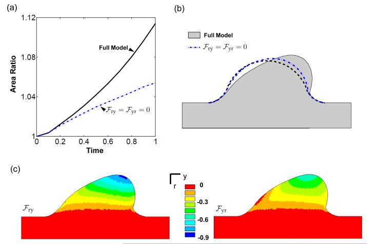
To assess the importance of the shear deformations in capturing the valve morphology, a simulation was performed in which the shear components of were not allowed to evolve. In this case, the update of the growth tensor was
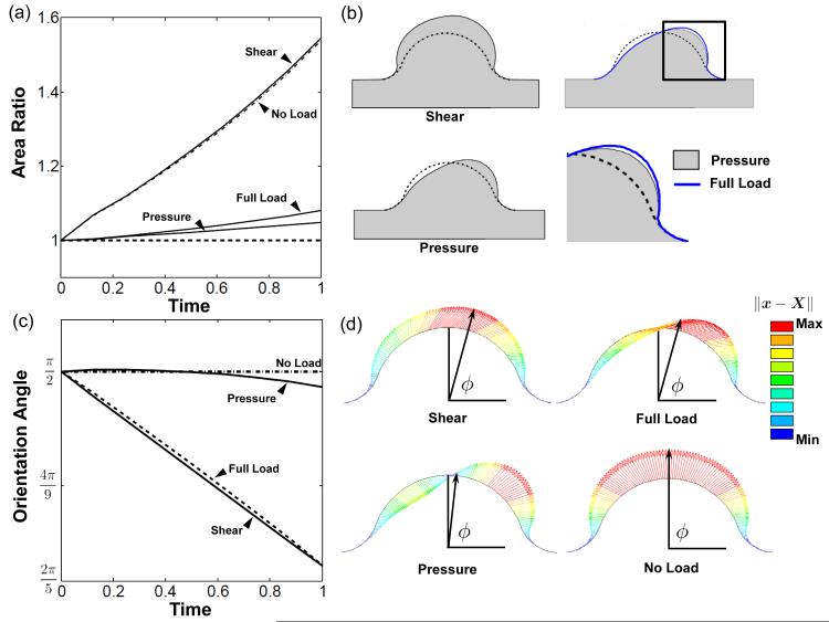
Computations were performed until 0.6 ≤ det() ≤ 2.6. Outside this range convergence difficulties occurred due to the accumulation of large inelastic deformations or large gradients of inelastic deformation. Simulation results were compared by using cross-sectional area, orientation angle, and color maps of computed mechanical outputs. The orientation angle, ϕ, was defined as the angle between the myocardial wall and the line that connects the bottom center of the cushion to the displaced position of the top-center point on the cushion surface (see Fig. 7d).
Fig. 7.
Pressure modulates volume change while shear directs surface remodeling. a) Area ratio plot for simulations with pressure only, shear tractions only, no load, and full load. b) Deformed configuration of each load scenario. The difference between full load and pressure only is shown in enlarged image of cushion leading edge. c) The shear traction directed migration of top center point. The pressure remodeled the cushion by removing and adding volume about the centerline of the cushion, displacing the center point very little. d) Vector plots depicting the displacement of cushion surface nodes and the orientation angle, ϕ. Vector length and color indicate displacement magnitude (∥x – X∥). Note that isotropic growth due to the homeostatic the stress does not affect the orientation angle.
3 Results
Fluid forces apply compressive load to AV cushion
In our simulations, the pressure drop across the AV canal was adjusted to match the experimental average velocity at the AV orifice (3.08 ± 0.99 cm/s) (Yalcin et al., 2011). A pressure drop of 62 dynes/cm2 (0.046 mmHg) generated a parabolic velocity flow profile through the AV orifice with an average velocity of 3.07 cm/s (Fig. S2). The Reynolds number through the AV orifice was Re = 5 which can be considered laminar for tube flow. The flow profile in the AV orifice during peak velocity was previously calculated by using actual HH27 AV canal geometries (36.6 cm/s, Yalcin et al. 2011). To validate our idealized geometry, we simulated peak flow through the orifice (ΔP = 1200 dynes/cm2, Vavg = 36 cm/s, Fig. S2b). The velocity profile resembled a plug flow, and agreed well with the prior study. This indicated that the axisymmetric AV canal and semi-circular cushion geometries were adequate approximations.
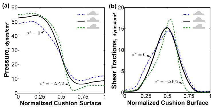
The AV canal pressure rapidly dropped from 52 dynes/ cm2 on flow entrance surface to 7 dynes/cm2 on the flow exit surface of the cushion, mainly due to the narrowing of the valve orifice. The shear tractions were oriented in the direction of flow, and their magnitude was symmetrically distributed about the cushion surface (solid, Fig. 4b). As the cushion evolved, the fluid loads would change based on the evolved cushion geometry. Expansion of the cushion increased the pressure drop across the cushion surface, while retraction decreased the pressure drop (dash and dash-dot respectively, Fig. 4a). A similar trend was seen in the shear traction, with the magnitude of maximum shear increasing with cushion expansion and decreasing with retraction (Fig. 4b). The symmetry of the shear traction profile declined as the initial geometric symmetry of the cushions degenerated. Together, the average hemodynamic loads put the AV cushion in a compressive and sheared state throughout the cardiac cycle.
Fig. 4.
Valve-like morphology generates fluid force profiles that promote further valve elongation and condensation. a) Plot of pressure distribution on the AV cushions at initial loading (solid) and after evolution with σ* = 0 (dash-dot) and (dash). b) The shear traction distribution becomes less symmetric as the cushion evolves asymmetrically. The maximal shear stress occurs at the leading edge of cushion. Normalized cushion surface denoted by red dashed line between point A and B in Fig. 2b
AV cushion dilatation rate is negative under fluid loading
The time derivative of the inelastic Jacobian, or dilatation rate (Eq. 9), determines the rate at which material is introduced or removed during the inelastic deformation.
| (9) |
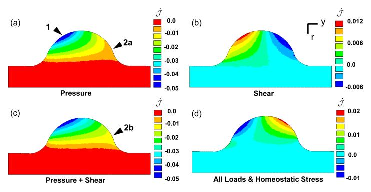
Included in Eq. 9 is the growth rate parameter a(r) which varies in the radial direction from a value of zero at the cushion/myocardium interface to a value of one on the axis of symmetry. The initial dilatation rate of the entire cushion under only the pressure load is negative, with the highest resorption rate at the top of the entrance surface (arrow 1 Fig. 5a). The shear tractions induced a positive dilatation rate on the inflow side and a negative on the exit, but the rate is an order of magnitude less than the pressure-induced dilatation rate. The difference in magnitude of the rates is due to 1) the difference in applied load magnitude, and 2) the nature of shear deformations to intrinsically drive distortion and not dilatation. This is seen in the case of a pure shear deformation, k, which contributes k2 terms to the diagonal components of the stress, where typically k < 1. Though the pressure is the dominant load on the entrance side of the cushion, it is of the same order of magnitude as the shear tractions on the exit side of cushion near the top (Fig. 4). It is in this region that the shear tractions modulate the inelastic dilatation rate, by increasing the resorption rate near the myocardial interface on flow exit side of the cushion (arrows 2a-b Fig. 5 a,c). The hemodynamic loads initially place the cushions into a state of resorption, which is only exacerbated by cushion expansion (dash-dot Fig. 4).
Fig. 5.
Compressive fluid loads stimulate negative dilation of AV cushion. Color maps of after initial loading with a) pressure load only, b) shear tractions only, c) all applied loads, and d) all loads with homogenous homeostatic stress . The resorption rate was highest at the inflow surface of the cushion (arrow 1). The shear tractions increase the rate of resorption on the back side of the cushion at the interface with the myocardium (arrow 2a-b). Compressive homeostatic stress shifts dilatation rate into a positive growth range. Color map in units of [1/t].
We propose the tissue responds to this compressive load by acquiring a preferential, homeostatic, compressive stress state. With limited data on the magnitude and spatial distribution of the homeostatic stress, we assume a homogenous, isotropic stress state with a magnitude proportional to the pressure drop across the AV canal (ΔP). As this pressure largely determines the stress state of the AV cushions, it is plausible that the homeostatic stress state would be sensitive to this load. With the incorporation of this homeostatic stress state, the initial dilatation rate uniformly increases in the cushion, resulting in volumetric expansion on the flow exit side of cushion, while maintaining resorption on flow entrance side (Fig. 5d). The combination of the fluid forces with homeostatic stress provides an initial rate of dilatation conducive to generate AV cushion morphology.
Valve-like morphology simulated with time averaged fluid force and isotropic homoestatic stress
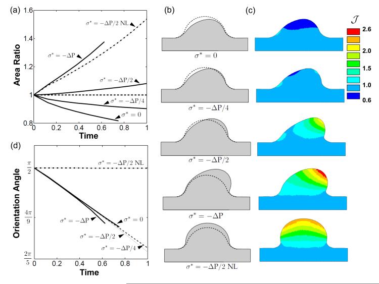
The evolution of the AV cushion under different load conditions was analyzed through comparison of cross-sectional area and the migration of the top-center point of the cushion surface. As anticipated, without a homeostatic stress the AV cushion volume contracted (Fig. 6a), but in a spatially dependent manner. More volume was removed on inflow side of cushion than outflow, and the cushion even expanded in a small region on the inflow side at the cushion/myocardial interface (Fig. 6c). The area ratio increased as the magnitude of the compressive homeostatic stress increased. A net increase in area was seen at magnitudes of –ΔP/2 and ΔP, while –ΔP/4 was still a net decrease. These area changes are evident from the evolved configurations shown in Fig. 6b (t = 0.6).
Fig. 6.
Fluid force distribution and homeostatic stress state generate valve-like morphology. a) Plot of AV cushion cross-sectional area normalized to initial area versus evolution time. Several compressive, isotropic, homeostatic stress states are shown. Note that a nonzero homeostat will stimulate remodeling when no load (NL) is applied. b) Plots of evolved configurations after removal of load for all scenarios. c) Color map of the inelastic Jacobian, , which details the spatial distribution of cushion expansion or resorption. d) The top center cushion surface evolves in the direction of flow as seen by the decrease in orientation angle over time. The orientation angle, ϕ, was defined as the angle between the myocardial wall and the line that connects the bottom center of the cushion to the displaced position of the top-center point on the cushion surface.
With σ* = –ΔP/2I and no fluid load applied (NL), the AV cushion ballooned into the AV canal (Fig. 6b). The cross-sectional area increased significantly, while maintaining a constant orientation angle of π/2. This determined that an isotropic homeostatic stress contributes directly to the volume change of the evolved cushion, and not the orientation. All loaded simulations had the same initial rate of change of the orientation angle, regardless of homeostatic tissue stress value. This indicated that the hemodynamic forces, not the homeostatic stress, directed the cushion shape change. The orientation angle began to diverge between the simulations after t = 0.5, with large homeostatic stress magnitudes generating smaller angles (Fig. 6d). This is a consequence of the elevated hemodynamic loads experienced by cushions with net volume addition.
The combination of the fluid forces with σ* = –ΔP/2I resulted in increased cushion volume and elongated morphology, similar to that of later stage valves. The other homeostatic stress magnitudes tested resulted in either deficient or excessive volume addition, creating retracted or thickened cushions (Fig. 6b). New tissue was primarily introduced at the cushion tip, with tissue resorption occurring on the inflow cushion surface (Fig. 6c). The evolved cushion geometry increases the fluid pressure on the inflow surface and reduces the pressure on the exit surface of the cushion (Fig. 4a), encouraging this fin-like shape. This suggests that cushion growth and remodeling is supported by a positive feedback process, whereby hemodynamic forces created by the asymmetric fin shape promote further condensation and elongation of the cushion.
Differential roles of pressure and shear traction in cushion formation
The hemodynamic loads on the AV cushion are sufficient to remodel a cushion with σ* = –ΔP/2I into a valve-like shape. This elongated and condensed shape is primarily a consequence of the fluid pressure, as evidenced by the pressure-only simulations (Fig. 7). As seen in the dilatation rates (Fig. 5), the pressure stimulates tissue removal on the flow entrance side of cushion, and expansion on the flow exit side. The pressure significantly decreased the rate of volume increase compared to the no load evolution (Fig. 7a). The shear tractions had little effect on cushion volume, although a slight increase was observed at the leading edge of the cushion in the full-load model versus the pressure only model (Fig. 7b). The magnitude of the shear tractions are maximal in this region, and promote distortion and thinning of the cushion leading edge.
The fluid pressure had little effect on orientation angle, while the shear tractions were the dominant stimuli of this metric (Fig. 7c). The pressure directed the valve-like morphology, but did so without significant displacement of the top center cushion surface (Fig. 7d). In this way, volume was selectively removed or added about the center line of the cushion. The top center point significantly migrated under shear loading. This may indicate that shear tractions are still important for the remodeling of the AV cushion surface, even if not important for overall cushion volume change.
Growth and remodeling induces residual stress
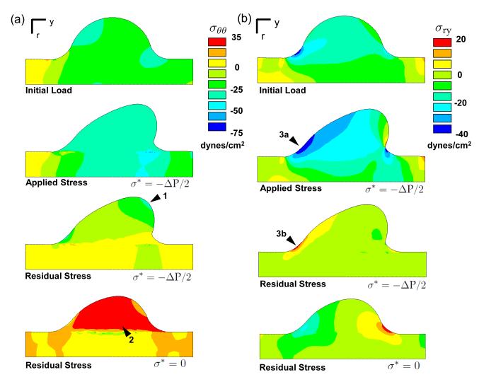
Radial and axial stress concentrations develop during the evolution at the cushion/myocardium interface on the flow exit cushion surface (arrows Fig. S3a-b). Both the pressure and shear tractions contribute to the location and intensity of this stress. After removal of the fluid load, the cushion relaxes to the evolved configuration, which is not stress free. The stresses in this configuration, termed residual stresses, are introduced by differential tissue growth and remodeling during the evolution. The cushion/myocardium interface develops residual stresses because of the difference in growth rate across that boundary, as the myocardium does not grow in this simulation (Fig. 8a, S3). Even in the loaded state, the continuity of the stress field is disrupted along this interface by prior inelastic deformations. The radial and axial residual stresses are small relative to their counterparts in the loaded configuration (Fig. S3). In contrast, the circumferential residual stresses are of the same sign and order of magnitude as the loaded stress state (Fig. 8a). The compressive circumferential residual stress has two causes. First, growth in the radial direction places the tissue closer to the axis of symmetry where it is under higher compressive stress due to the reduced circumference. Second, while this higher compressive stress would normally stimulate compensatory tissue resorption, the homeostatic stress reduces the resorption rate, which means the tissue is still in compression even after load removal. The converse is true in the simulation with no homeostat, where a tensile residual stress accrues in the circumferential direction. The magnitude and sign of the circumferential residual stress appears to be predominantly a consequence of the cushion growing in a tube.
Fig. 8.
Growth and remodeling induces residual stress. a) Circumferential residual stress is influenced by growth in the radial-axial plane. The residual stress is maximal at the cushion leading edge, where the radial position in the AV canal is shortest (arrow 1). It is compressive because 1) circumferential stress is higher than the homeostatic stress which stimulates growth, and 2) the circumferential retractions are insufficient to match the reduced space due to radial growth toward axis of symmetry. With σ* = 0, the applied compressive load stimulated circumferential resorption which resulted in a tensile residual stress (arrow 2). b) The residual shear stress is mainly localized to the cushion/myocardium interface on the inflow surface (arrows 3a-b). The negative applied shear stress results in a positive residual stress due to the accruement of inelastic shear deformation in that region.
The residual shear stress in r-y direction is also of similar magnitude to the loaded shear stress near the cushion/myocardium interface on the inflow side of cushion (arrow Fig. 8b). The applied load induces a negative shear stress in that region, which results in an inelastic shear deformation. When the load is removed, the tissue attempts to return to its original configuration, which creates a positive shear stress in this remodeled region. In this stress-based growth model, the residual stress does influence the evolution of the cushion. Relaxation of the residual stress was investigated by incrementally updating the stress-free reference configuration to the unloaded evolved configuration. The residual stresses were then disregarded at each update. In this relaxed model, the cross-sectional area and cushion morphology began to diverge from the non-relaxed model (Fig. S4). Though the differences were small for the evolution times investigated, these results support the possibility that residual stresses may induce distinct and functional differences at longer times.
Inelastic shear deformations are important for driving valve-like morphogenesis
The morphogenesis of the AV cushion includes not only an increase in tissue volume at this stage, but also significant change in shape. The inelastic shear deformations play a pivotal role in reproducing shape change in this growth model. The shear components of the growth and remodeling tensor are maximal at the tip of the AV cushion (Fig. 9c). The fluid shear tractions and tissue growth rate are also maximal in this region. A simulation was run in which the shear components did not evolve. In this situation the cushion grew in the direction of flow, but did not remodel as efficiently into the elongated and condensed valve shape (Fig. 9b). The cross-sectional area also increased at a slower rate in this simulation (Fig. 9a). This is most likely due to the difference in applied fluid forces between the two remodeled geometries. These results suggest that shear deformations, or shear remodeling, may be important in controlling valve morphology.
Fig. 9.
Inelastic shear deformations are key to recapitulating valve morphology. a) Removal of the inelastic shear components results in reduced cross-sectional area growth compared to the full growth law. b) Without shear components the cushion does evolve in the direction of flow (dash-blue), but has limited shape change. c) Color maps of the and display the large inelastic shear deformations throughout the cushion.
4 Discussion
The hemodynamic environment of the embryonic heart applies morphologically significant mechanical loads to the developing AV valves (review (Santhanakrishnan and Miller, 2011)). Experimental studies both support and contest shear stress as a mechanical stimulus of cushion development. The reduced shear tractions due to occluded blood flow in zebrafish resulted in defective cardiac looping, bulbus formation, and inflow/outflow tract fusion, which occur in hearts without AV cushions (Hove et al., 2003). Another study suggested that shear tractions are secondary effects compared to myocardial function (Bartman et al., 2004). Myocardial force was reduced through myofibrillar ATPase inhibition to the point of stagnant blood flow, but the AV cushions still developed. Our computational model indicated that fluid shear tractions do not significantly change cushion volume, but are instead responsible for cushion surface remodeling. Maximum shear tractions, and consequently inelastic shear deformation, were localized to the leading edge of the cushion (Fig. 4b, 9c). The fluid pressure predominantly directed the valve-like morphology through selective removal and addition of volume, in conjunction with a compressive, homeostatic stress state. Interestingly, the pressure had little effect on the evolution of the top center region of the cushion, while the shear tractions significantly elongated this region (Fig. 7d). Although the fluid shear tractions did not significantly alter cushion volume, their role in stimulating cellular and molecular signaling may be instrumental to the growth process (Groenendijk et al., 2005), but this is not represented in the current model.
Homeostatic reference states, defined in terms of both stress and strain, have become common features of tissue growth models (Humphrey and Rajagopal, 2003; Rodriguez et al., 1994; Taber, 2008). Evidence of a homeostatic stress state has been previously investigated in arteries (Chuong and Fung, 1986; Humphrey and Rajagopal, 2003; Taber and Humphrey, 2001). Opening angles of excised arteries show a non-homogenous residual stress distribution, which promotes a uniform circumferential and axial stress when the artery is loaded (Chuong and Fung, 1986). This suggested the existence of a uniform, preferential stress state maintained by the tissue. Although there is no data on the homeostatic stress state for AV cushions, the compressive fluid forces and the need of a directionally unbiased model motivated the use of a homogenous, isotropic, compressive stress state. This homeostatic stress was essential in generating a net increase in cushion volume needed to reproduce the growth of the cushion. In the present model, cessation of growth or remodeling would occur only if the internal and external pressure of the AV canal were constant and equal to the homeostatic stress of the AV cushion. The loading conditions for this growth equilibrium state are incompatible with fluid flow, indicating that at least remodeling, if not growth, is persistently active. Continuous growth and remodeling would not be appropriate for modeling homeostatis of an adult valve, but is a plausible feature of a morphogenesis model.
The isotropic homeostatic stress functionally represented an active growth process in the AV cushion, which was modulated by the distribution of the stress from the fluid loads. Where the applied stress was more compressive than the homeostatic stress, the tissue retracted; where it was less compressive, volume was added. This type of response is observed in left atrial ligation studies, where the left AV valve thickens due to a decrease in blood inflow and AV canal pressure (Sedmera et al., 1999). In our model this is seen in the ballooning of the cushion that occurs when no loads are applied, but the homeostatic stress is non-zero (Fig. 6). Thickened valves are a common pheno-type seen in gene knockout (KO) mice, such as TGFβ2 (Bartram et al., 2001), periostin (Snider et al., 2008), and collagen 11α1 (Lincoln et al., 2006). While it is possible that genetic aberrations may perhaps modulate the homeostatic stress, resulting in incorrect cushion volume, no method to measure the homeostatic stress in valves is currently known. It may be possible to infer cushion residual stresses, and then relate them to the homeostatic stress, through incision methods similar to those used to study arteries. At the same time, it is important to note that the biological rational of stress-based growth and consequently a stress-based homeostat is still a subject of debate in the morphomechanics community (Ambrosi et al., 2011). Different mechanical or molecular criteria may better define the nature of the tissue homeostatic state.
Several biological details were incorporated in the growth model. Fluid loads were determined from in vivo velocity measurement acquired from ultrasound imaging. The material law parameters were acquired from previous mechanical testing. The model also included a gradient in growth rate, which was motivated by cell distributions seen from AV cushion histology sections. More experimental work is needed to verify whether mass addition and ECM production is spatially dependant in this way. Although significant experimental data was incorporated in the model, additional biological features would enhance the predictability and insight of the simulation. Inclusion of multiple constituents through mixture theory is a step in this direction. Mixture theory approaches have successfully modeled constituent turnover and mechanical feedback responses in models of arteries (Humphrey and Rajagopal, 2003; Rachev and Jr, 2011). Incorporating molecular details into future growth and remodeling similations is essential for defining the relationships between cellular and tissue scale events. This is particular relevant for valve development as there are several gene-specific defective valve phenotypes with both physiologic and clinical significance.
In this study, we have correlated the distribution of the fluid loads and an isotropic homeostatic stress state with valve-like morphology of the AV cushions. Pressure appears to be the key load responsible for cushion growth and remodeling, but shear tractions may serve an important role in surface remodeling. Inelastic shear deformations were shown to be important for acquiring the valve-like evolved configuration. The model also indicated that the mechanical aspects of valvulogenesis may be self-propagating, as the elongated valve shape generated fluid force profiles which promoted further cushion elongation. While this elongated morphology is appropriate for modeling the AV cushion, it may not accurately portray growth and remodeling in other valves of the heart (de Lange et al., 2004; Lincoln et al., 2004). Additional refinements, such as increasing the degree of freedom of the cushion material at myocardium interface and including growth of the AV canal, may be necessary to reproduce the morphology of other leaflets. Novel in vitro and in vivo experiments are needed to establish the nature of the homeostatic state, which could be analyzed with this growth law. This model may also inform researchers on the optimal location or magnitude of mechanical perturbation needed to generate disease state animal models. For instance, the shear stress could be modulated by using blood viscosity modifiers, or the AV canal pressure drop decreased through left atrial ligation. In all, our growth model provides a useful framework on which to investigate morphological aspects of valve development, and motivates further experimental studies toward understanding mechanical signaling in vivo.
Supplementary Material
Acknowledgements
This project was funded by the American Heart Association (0830384N, JTB), National Institutes of Health (HL110328, JTB), The Hartwell Foundation (JTB) and the National Science Foundation (CBET-0955172, JTB; DGE0841291, PRB). The authors would like to thank Jen M. Richards for creating the drawing in Figure 2a.
Contributor Information
Philip R. Buskohl, Department of Mechanical and Aerospace Engineering 306 Weill Hall, Cornell University, Ithaca, NY 14853
James T. Jenkins, School of Civil and Environmental Engineering, Cornell University, Ithaca, NY 14853
Jonathan T. Butcher, Department of Biomedical Engineering, Cornell University, Ithaca, NY 14853
References
- Al-Roubaie S, Jahnsen ED, Mohammed M, Henderson-Toth C, Jones EA. Rheology of embryonic avian blood. Am J Physiol Heart C. 2011;301(6):H2473–81. doi: 10.1152/ajpheart.00475.2011. [DOI] [PubMed] [Google Scholar]
- Ambrosi D, Ateshian GA, Arruda EM, Cowin SC, Dumais J, Goriely A, Holzapfel GA, Humphrey JD, Kemkemer R, Kuhl E, Olberding JE, Taber LA, Garikipati K. Perspectives on biological growth and remodeling. J Mech Phys Solids. 2011;59(4):863–883. doi: 10.1016/j.jmps.2010.12.011. [DOI] [PMC free article] [PubMed] [Google Scholar]
- Ambrosi D, Guillou A. Growth and dissipation in biological tissues. Continuum Mech Therm. 2007;(5):245–251. [Google Scholar]
- Bartman T, Walsh EC, Wen KK, McKane M, Ren J, Alexander J, Rubenstein PA, Stainier DY. Early myocardial function affects endocardial cushion development in zebrafish. PLoS Biol. 2004;2(5):E129. doi: 10.1371/journal.pbio.0020129. [DOI] [PMC free article] [PubMed] [Google Scholar]
- Bartram U, Molin DG, Wisse LJ, Mohamad A, Sanford LP, Doetschman T, Speer CP, Poelmann RE, Gittenberger de Groot AC. Double-outlet right ventricle and overriding tricuspid valve reflect disturbances of looping, myocardialization, endocardial cushion differentiation, and apoptosis in tgf-beta(2)-knockout mice. Circ. 2001;103(22):2745–2752. doi: 10.1161/01.cir.103.22.2745. [DOI] [PubMed] [Google Scholar]
- Beloussov LV, Grabovsky VI. Morphomechanics: goals, basic experiments and models. Int J Dev Biol. 2006;50(2-3):81–92. doi: 10.1387/ijdb.052056lb. [DOI] [PubMed] [Google Scholar]
- Beloussov LV, Luchinskaia NN. Biomechanical feedback in morphogenesis, as exemplified by stretch responses of amphibian embryonic tissues. Biochem Cell Biol. 1995;73(7-8):555–563. doi: 10.1139/o95-061. [DOI] [PubMed] [Google Scholar]
- Biechler SV, Potts JD, Yost MJ, Junor L, Goodwin RL, Weidner JW. Mathematical modeling of flow-generated forces in an in vitro system of cardiac valve development. Ann Biomed Eng. 2010;38(1):109–117. doi: 10.1007/s10439-009-9824-9. [DOI] [PMC free article] [PubMed] [Google Scholar]
- Buskohl PR, Gould RA, Butcher JT. Quantification of embryonic atrioventricular valve biomechanics during morphogenesis. J Biomech. 2012;45(5):895–902. doi: 10.1016/j.jbiomech.2011.11.032. [DOI] [PMC free article] [PubMed] [Google Scholar]
- Butcher JT, Markwald RR. Valvulogenesis: the moving target. Philos T Roy Soc B. 2007;362(1484):1489–1503. doi: 10.1098/rstb.2007.2130. [DOI] [PMC free article] [PubMed] [Google Scholar]
- Butcher JT, McQuinn TC, Sedmera D, Turner D, Markwald RR. Transitions in early embryonic atrioventricular valvular function correspond with changes in cushion biomechanics that are predictable by tissue composition. Circ Res. 2007;100(10):1503–1511. doi: 10.1161/CIRCRESAHA.107.148684. [DOI] [PubMed] [Google Scholar]
- Chuong CJ, Fung YC. On residual stresses in arteries. J Biomech Eng. 1986;108(2):189–192. doi: 10.1115/1.3138600. [DOI] [PubMed] [Google Scholar]
- Cowin SC, Van Buskirk WC. Surface bone remodeling induced by a medullary pin. J Biomech. 1979;12(4):269–276. doi: 10.1016/0021-9290(79)90069-1. [DOI] [PubMed] [Google Scholar]
- de Lange FJ, Moorman AF, Anderson RH, Manner J, Soufan AT, de Gier-de Vries C, Schneider MD, Webb S, van den Hoff MJ, Christoffels VM. Lineage and morphogenetic analysis of the cardiac valves. Circ Res. 2004;95(6):645–654. doi: 10.1161/01.RES.0000141429.13560.cb. [DOI] [PubMed] [Google Scholar]
- Eisenberg LM, Markwald RR. Molecular regulation of atrioventricular valvuloseptal morphogenesis. Circ Res. 1995;77(1):1–6. doi: 10.1161/01.res.77.1.1. [DOI] [PubMed] [Google Scholar]
- Forouhar AS, Liebling M, Hickerson A, Nasiraei-Moghaddam A, Tsai HJ, Hove JR, Fraser SE, Dickinson ME, Gharib M. The embryonic vertebrate heart tube is a dynamic suction pump. Science. 2006;312(5774):751–753. doi: 10.1126/science.1123775. [DOI] [PubMed] [Google Scholar]
- Garikipati K, Arruda EM, Grosh K, Narayanan H, Calve S. A continuum treatment of growth in biological tissue: mass transport coupled with mechanics. J Mech Phys Solids. 2004;52(7):1595–1625. [Google Scholar]
- Gonzalez-Sanchez A, Bader D. In vitro analysis of cardiac progenitor cell differentiation. Dev Biol. 1990;139(1):197–209. doi: 10.1016/0012-1606(90)90288-t. [DOI] [PubMed] [Google Scholar]
- Groenendijk BC, Hierck BP, Vrolijk J, Baiker M, Pourquie MJ, Gittenberger de Groot AC, Poelmann RE. Changes in shear stress-related gene expression after experimentally altered venous return in the chicken embryo. Circ Res. 2005;96(12):1291–1298. doi: 10.1161/01.RES.0000171901.40952.0d. [DOI] [PubMed] [Google Scholar]
- Hinton RB, Lincoln J, Deutsch GH, Osinska H, Manning PB, Benson DW, Yutzey KE. Extracellular matrix remodeling and organization in developing and diseased aortic valves. Circ Res. 2006;98(11):1431–1438. doi: 10.1161/01.RES.0000224114.65109.4e. [DOI] [PubMed] [Google Scholar]
- Hogers B, DeRuiter MC, Gittenberger de Groot AC, Poelmann RE. Unilateral vitelline vein ligation alters intracardiac blood flow patterns and morphogenesis in the chick embryo. Circ Res. 1997;80(4):473–481. doi: 10.1161/01.res.80.4.473. [DOI] [PubMed] [Google Scholar]
- Hove JR, Koster RW, Forouhar AS, Acevedo-Bolton G, Fraser SE, Gharib M. Intracardiac fluid forces are an essential epigenetic factor for embryonic cardiogenesis. Nature. 2003;421(6919):172–177. doi: 10.1038/nature01282. [DOI] [PubMed] [Google Scholar]
- Hu N, Clark EB. Hemodynamics of the stage 12 to stage 29 chick embryo. Circ Res. 1989;65(6):1665–1670. doi: 10.1161/01.res.65.6.1665. [DOI] [PubMed] [Google Scholar]
- Humphrey JD, Rajagopal KR. A constrained mixture model for arterial adaptations to a sustained step change in blood flow. Biomech Model Mechan. 2003;2(2):109–126. doi: 10.1007/s10237-003-0033-4. [DOI] [PubMed] [Google Scholar]
- Kruithof BP, Krawitz SA, Gaussin V. Atrioventricular valve development during late embryonic and postnatal stages involves condensation and extracellular matrix remodeling. Dev Biol. 2007;302(1):208–217. doi: 10.1016/j.ydbio.2006.09.024. [DOI] [PubMed] [Google Scholar]
- Lin IE, Taber LA. A model for stressinduced growth in the developing heart. J Biomech Eng. 1995;117(3):343–349. doi: 10.1115/1.2794190. [DOI] [PubMed] [Google Scholar]
- Lincoln J, Alfieri CM, Yutzey KE. Development of heart valve leaflets and supporting apparatus in chicken and mouse embryos. Dev Dynam. 2004;230(2):239–250. doi: 10.1002/dvdy.20051. [DOI] [PubMed] [Google Scholar]
- Lincoln J, Florer JB, Deutsch GH, Wenstrup RJ, Yutzey KE. Colva1 and colxia1 are required for myocardial morphogenesis and heart valve development. Dev Dynam. 2006;235(12):3295–3305. doi: 10.1002/dvdy.20980. [DOI] [PubMed] [Google Scholar]
- Lubarda VA, Hoger A. On the mechanics of solids with a growing mass. Int J Solids Struct. 2002;39(18):4627–4664. [Google Scholar]
- Miller LA. Fluid dynamics of ventricular filling in the embryonic heart. Cell Biochem Biophys. 2011;61(1):33–45. doi: 10.1007/s12013-011-9157-9. [DOI] [PubMed] [Google Scholar]
- Munoz JJ, Conte V, Miodownik M. Stress-dependent morphogenesis: continuum mechanics and truss systems. Biomech Model Mechan. 2010;9(4):451–467. doi: 10.1007/s10237-009-0187-9. [DOI] [PubMed] [Google Scholar]
- Person AD, Klewer SE, Runyan RB. Cell biology of cardiac cushion development. Int Rev Cytol. 2005;243:287–335. doi: 10.1016/S0074-7696(05)43005-3. [DOI] [PubMed] [Google Scholar]
- Rachev A, Gleason RL., Jr Theoretical study on the effects of pressure-induced remodeling on geometry and mechanical non-homogeneity of conduit arteries. Biomech Model Mechan. 2011;10(1):79–93. doi: 10.1007/s10237-010-0219-5. [DOI] [PMC free article] [PubMed] [Google Scholar]
- Ramasubramanian A, Nerurkar NL, Achtien KH, Filas BA, Voronov DA, Taber LA. On modeling morphogenesis of the looping heart following mechanical perturbations. J Biomech Eng. 2008;130(6):061018. doi: 10.1115/1.2978990. [DOI] [PMC free article] [PubMed] [Google Scholar]
- Ramasubramanian A, Taber LA. Computational modeling of morphogenesis regulated by mechanical feedback. Biomech Model Mechan. 2008;7(2):77–91. doi: 10.1007/s10237-007-0077-y. [DOI] [PMC free article] [PubMed] [Google Scholar]
- Rodriguez EK, Hoger A, McCulloch AD. Stress-dependent finite growth in soft elastic tissues. J Biomech. 1994;27(4):455–467. doi: 10.1016/0021-9290(94)90021-3. [DOI] [PubMed] [Google Scholar]
- Santhanakrishnan A, Miller LA. Fluid dynamics of heart development. Cell Biochem Biophys. 2011;61(1):1–22. doi: 10.1007/s12013-011-9158-8. [DOI] [PubMed] [Google Scholar]
- Schroeder JA, Jackson LF, Lee DC, Camenisch TD. Form and function of developing heart valves: coordination by extracellular matrix and growth factor signaling. J Mol Med. 2003;81(7):392–403. doi: 10.1007/s00109-003-0456-5. [DOI] [PubMed] [Google Scholar]
- Sedmera D, Pexieder T, Rychterova V, Hu N, Clark EB. Remodeling of chick embryonic ventricular myoarchitecture under experimentally changed loading conditions. Anat Rec. 1999;254(2):238–252. doi: 10.1002/(SICI)1097-0185(19990201)254:2<238::AID-AR10>3.0.CO;2-V. [DOI] [PubMed] [Google Scholar]
- Snider P, Hinton RB, Moreno-Rodriguez RA, Wang J, Rogers R, Lindsley A, Li F, Ingram DA, Menick D, Field L, Firulli AB, Molkentin JD, Markwald R, Conway SJ. Periostin is required for maturation and extracellular matrix stabilization of noncardiomyocyte lineages of the heart. Circ Res. 2008;102(7):752–760. doi: 10.1161/CIRCRESAHA.107.159517. [DOI] [PMC free article] [PubMed] [Google Scholar]
- Taber LA. Theoretical study of beloussov’s hyper-restoration hypothesis for mechanical regulation of morphogenesis. Biomech Model Mechan. 2008;7(6):427–441. doi: 10.1007/s10237-007-0106-x. [DOI] [PMC free article] [PubMed] [Google Scholar]
- Taber LA. Towards a unified theory for morphomechanics. Philos T Roy Soc A. 2009;367(1902):3555–3583. doi: 10.1098/rsta.2009.0100. [DOI] [PMC free article] [PubMed] [Google Scholar]
- Taber LA, Humphrey JD. Stress-modulated growth, residual stress, and vascular heterogeneity. J Biomech Eng. 2001;123(6):528–535. doi: 10.1115/1.1412451. [DOI] [PubMed] [Google Scholar]
- Taber LA, Zhang J, Perucchio R. Computational model for the transition from peristaltic to pulsatile flow in the embryonic heart tube. J Biomech Eng. 2007;129(3):441–449. doi: 10.1115/1.2721076. [DOI] [PubMed] [Google Scholar]
- Vermot J, Forouhar AS, Liebling M, Wu D, Plummer D, Gharib M, Fraser SE. Reversing blood flows act through klf2a to ensure normal valvulogenesis in the developing heart. PLoS Biol. 2009;7(11):e1000246. doi: 10.1371/journal.pbio.1000246. [DOI] [PMC free article] [PubMed] [Google Scholar]
- Yalcin HC, Shekhar A, McQuinn TC, Butcher JT. Hemodynamic patterning of the avian atrioventricular valve. Dev Dynam. 2011;240(1):23–35. doi: 10.1002/dvdy.22512. [DOI] [PMC free article] [PubMed] [Google Scholar]
Associated Data
This section collects any data citations, data availability statements, or supplementary materials included in this article.


