Abstract
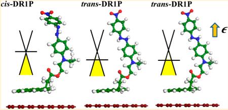
Noncovalent functionalization provides an effective way to modulate the electronic properties of graphene. Recent experimental work has demonstrated that hybrids of dipolar phototransductive molecules tethered to graphene are reversibly tunable in doping. We have studied the electronic structure characteristics of chromophore/graphene hybrids using dispersion-corrected density functional theory. The Dirac point of noncovalently functionalized graphene shifts upward via cis–trans isomerism, which is attributed to a change in the chromophore’s dipole moment. Our calculation results reveal that the experimentally observed reversible doping of graphene is attributed to the change in charge transfer between the light-switchable chromophore and graphene via isomerization. Furthermore, we show that by varying the electric field perpendicular to the supramolecular functionalized graphene, additional tailoring of graphene doping can be accomplished.
INTRODUCTION
Graphene is well-known for its unique properties, including its remarkable thermal conductivity, charge transport, and mechanical strength.1-3 Graphene has a sp2-hybridized planar network of carbons with extended π conjugation that makes it an ideal material for electronics applications.1-6 Although covalent functionalization of graphene provides a way to tailor its electronic properties, the distortion of the sp2 network remains difficult to control.7-25 On the other hand, non-covalent functionalization of graphene is a controlled method whereby the π network is preserved, while the corresponding electronic properties are tuned by varying the dopant.26-28 A controlled graphene doping technique is highly desirable for building stable devices with potential applications as biosensors and field-effect transistors.29,30
Molecules with extended conjugated systems, such as pyrene, have been employed for noncovalent binding to graphene due to the π–π interactions between pyrene and gaphene sp2-hybridized networks;1,31 however, strong binding capability alone is not enough to achieve the desired effect due to pyrene’s ineffectiveness as a dopant for practical applications.32-34 One way to circumvent this issue is to utilize compounds derived from pyrene and dipolar molecules. The resulting pyrene derivative provides an opportunity to bind a strong dopant to graphene while preserving its unique electronic characteristics. Recent experimental work has shown that when tethered to the graphene’s surface, the pyrene azo compound disperse red 1 pyrene (DR1P) is effective at modulating graphene doping via photoisomerization.26 An increase in its dipole moment can be accomplished as the azobenzene-derived chromophore switches from a cis to a trans isomer, leading to distinctive doping behavior.15,26 However, an in-depth understanding of these charge transfer interactions remains unclear.33,34 Here, we report results based on dispersion-corrected density functional theory (DFT) calculations.35 Our results shed further light on the correlation between changes in dipole moment and charge transfer. Moreover, we investigate the effect of applying a perpendicular electric bias to tune graphene’s electronic properties.
COMPUTATIONAL DETAILS
We have performed calculations based on dispersion-corrected DFT to characterize structural and electronic properties. For the exchange-correlation functional, the gradient-corrected (GGA) Perdew–Burke–Ernzerhof (PBE) form was used.35 To account for the interlayer van der Waals interactions, we utilized a dispersion correction that is based on the Tkatchenko–Scheffier (TS) scheme, which exploits the relationship between polarizability and volume.36 The semi-empirial TS dispersion correction takes into account the relative variation in dispersion coefficients of various atomic bondings. It weights the values extracted from the high-quality ab initio database with atomic volumes derived from partitioning the self-consistent electron density.36 The TS scheme has been successfully applied to a variety of systems for a much improved accuracy. Specifically, for graphite, local-density approximation overestimates the binding between the graphene layers, while GGA is very weak in binding.37,38 Inclusion of the dispersion correction yields the correct layer distance of 3.719 Å, which is in good agreement with experiments.37
We have used a 7 × 7 rhombus cell that consistents of 98 carbon atoms and the DR1P molecule. The DR1P molecule has a pyrene group along with an azobenzene group. The DR1P has 35 carbon, 4 nitrogen, 32 hydrogen, and 4 oxygen atoms. Shown in Figure 1 are the optimized structures of cis-DR1P and trans-DR1P, respectively. As seen from Figure 1, the pyrene is nearly parallel to the graphene surface (with a slightly slanted angle of 6.5°). The azobenzene group serves as an optical switch to control the doping of the fractionalized graphene.26 In the cis-DR1P conformation, the azobenzene group bends down, whereas the azobenzene group in the trans-DR1P stretches out. The stretched and bent conformations are characteristic of the light-switch molecule.26 The dipole moment of 9D in the trans conformation of azobenzene reduced to 6D in cis.26
Figure 1.
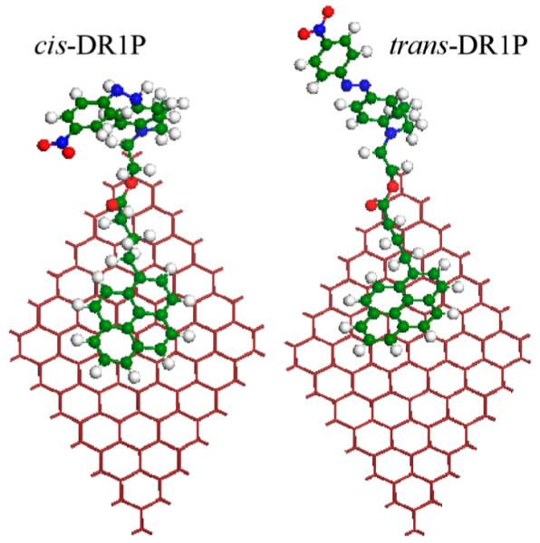
Optimized structures of cis- and trans-DR1P isomers tethered to the graphene’s surface in the left and right panels, respectively. Red, blue, and green spheres represent oxygen, nitrogen, and carbon atoms, respectively.
Furthermore, we have applied electric bias to both cis-DR1P and trans-DR1P. Using first-principles calculations, we found that in an applied electric field, the electrons of the trans-DR1P molecules are polarized. The quantum mechanical analysis for the description of a polarizable, neutral particle in a homogeneous electric field can be applied to an electrostatic potential distribution over the entire molecule.
Periodic-boundary conditions were employed with a super-cell in the x–y plane that was large enough to eliminate interactions between neighboring replicas. A double numerical basis was sufficient for the grid integration of the charge density to converge. All structures were relaxed with forces less than 0.01 eV/Å.33
RESULTS AND DISCUSSION
The binding energy for trans-DR1P and cis-DR1P is −1190.6 and −1160.7 eV, respectively. The trans-DR1P has lower energy than cis-DR1P, and the isomerism can be induced by illumination of UV and white light.26 The effect of doping can be readily clarified by the shift of the Dirac point in the band structure.38 As seen from Figure 2, the Dirac point is located at the Fermi level in pristine graphene as well as in the cis-DR1P/graphene hybrid, whereas the corresponding Dirac point is shifted upward from the Fermi level in the trans-DR1P/graphene hybrid. The bands associated with the two DR1P isomers are characterized as flat bands, in contrast with the dispersed bands of graphene. For the trans-DR1P/graphene hybrid, there are two flat bands that are in close proximity to the Fermi level. Specifically, the two flat bands can be viewed as arising from the hybridization between graphene’s π-band and the highest occupied molecular orbital (HOMO) and HOMO-1, respectively. The relative location of the HOMO-derived and HOMO-1-derived bands of DR1P plays an important role in electron doping. In this case, trans-DR1P provides a pool for electron doping because the HOMO-derived DR1P band is very close to the Fermi level. The strong doping of DR1P is also manifested in the amount of upward shift of the Dirac point. Furthermore, trans-DR1P has p-doping, whereas for cis-DR1P, there is no shift of the Dirac point, implying a much less effort of doping. As seen from the band structure (Figure 2), the HOMO-derived band of trans-DR1P is closer to the Fermi level, and the LUMO-derived band is located far above the Fermi level. The latter implies that the trans-DR1P serves as a charge donor to graphene.37
Figure 2.
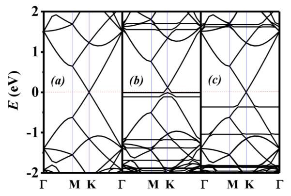
Calculated band structures of (a) pristine graphene, (b) trans-DR1P on graphene, and (c) cis-DR1P on graphene, respectively. Γ = (0, 0), K = (π/3a, 2π/3a), M = (0, π/2a), where a = 17.220 Å. The Fermi level is shifted to 0 eV (red dashed line).
On the other hand, the two corresponding flat bands for the cis-DR1P/graphene hybrid are located relatively far away from the Fermi level and are separated from one another. Hence, the doping of graphene by the cis-DR1P is negligible. It is worth noting that there is no shift of the Dirac point for cis-DR1P-functionalized graphene. Although it is evident that the cis–trans isomerization yields changes in electronic doping, a quantitative characterization of the doping behavior through the shifts of Dirac point is useful.
To further pursue the charge transfer behavior, we illustrate in Figure 3 the isosurfaces associated with the valence band maximum (VBM) and conduction band minimum (CBM) of both cis and trans-DR1P/graphene. For the trans-DR1P/graphene hybrid, the VBM charge density is located on both the pyrene ring and the lower ring of the azobenzene group, whereas that of the cis-DR1P/graphene hybrid is concentrated on the whole azobenzene group only.
Figure 3.
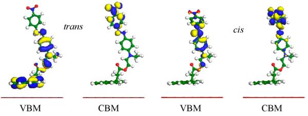
Isosurfaces of the valence band maximum (VBM) and conduction band minimum (CBM) for cis- and trans-DR1P on graphene with 0.2 au isovalue.
This difference in charge confinement is correlated with distinct doping behaviors. Charge transfer plays a major role in graphene doping by the cis and trans chromophores. To characterize charge transfer, we extract the Mulliken charges for both isomers, which are 0.01 and 0.02 e for the cis- and trans-DR1P/graphene hybrids, respectively (see Table 1). Charge transfer is more than twice as high for the trans-DR1P/graphene hybrid compared with the cis hybrid. It is worth noting that there exists intramolecular charge transfer between the pyrene and azobenzene rings, as well. The trans conformation of the azobenzene group allows for long-range charge transfer interactions between the two rings, thereby illustrating its distinct doping character. On the other hand, the corresponding charge transfer in cis-DR1P is much weaker due to its smaller dipole moment. These results are in agreement with experimental findings.26 Specifically, it was found that the trans-DR1P isomer is a stronger hole dopant than cis-DR1P, which when tethered to the graphene’s surface yields an ~18% decrease in doping without further synthesis.
Table 1.
Mulliken Charge of Individual Groups on cis and trans-DR1P/Graphene with Applied Electric Fields
|
cis-DR1P/graphene (e) |
trans-DR1P/graphene (e) |
|||||||
|---|---|---|---|---|---|---|---|---|
| electric field (V/Å) | graphene | pyrene | azo-group | cis-DR1P | graphene | pyrene | azo-group | cis-DR1P |
| 0 | 0.000 | 0.238 | −0.246 | −0.008 | −0.213 | −0.38 | 0.247 | 0.209 |
| 0.05 | 0.001 | 0.222 | −0.226 | 0.00 | 0.809 | 0.372 | −1.180 | −0.808 |
| −0.05 | −0.006 | 0.263 | −0.226 | 0.001 | 0.780 | −1.600 | 0.827 | −0.773 |
Although DR1P/graphene hybrids are tunable through cis–trans photoisomerization, it is desirable to explore additional options to control graphene doping. To this end, we have investigated the effect of applying an electric bias. Shown in Figure 4 is the electronic structure of the trans-DR1P/graphene hybrid when an electric field of 0.05 and −0.05 V/Å is applied. The positive and negative electric biases correspond to the field directions from graphene to DR1P and from DR1P to graphene, respectively. Negative electric bias up-shifts the Dirac point of the structure by a factor of 2 higher than a positive electric bias, which indicates that this system can be further tuned with applied electric bias in addition to photoisomerism. Consequently, the dipole moment of trans-DR1P is altered by the electric field, thereby allowing the graphene sheet to donate electrons to trans-DR1P via the pyrene ring, which is a favorable direction for charge transfer.
Figure 4.
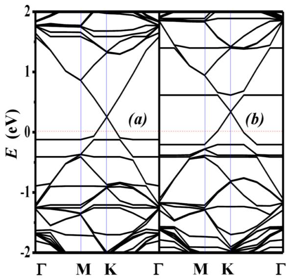
Calculated band structure of trans-DR1P on graphene with electric biases of (a) 0.05 V/Å (from graphene to DR1P) and (b) −0.05 V/Å (from DR1P to graphene), respectively.
The application of an electric bias in either direction enhances hole-doping as characterized by considerable shifts in the Dirac point. The trans-DR1P component undergoes intramolecular charge transfer as well as interlayer charge transfer. Specifically, with an electric field in the direction from graphene to trans-DR1P, the azobenzene ring becomes negatively charged, and the pyrene component shifts to being positively charged. In contrast, a negative electric bias has the opposite effect. Incremental increase in the electric bias leads to increased doping, as characterized by further Dirac point shifts, until a saturation point is eventually reached. This doping effect is more pronounced when a negative electric bias is applied. For cis-DR1P, the corresponding shift in the Dirac point with applied electric bias is not observed. This result contrasts with experimental findings, which report that there is an observed doping of graphene by cis-DR1P.26 It is worth noting that the charge on the azobenzene component of cis-DR1P does not change with electric bias, indicating that its lower dipole moment renders it as an ineffective dopant.
CONCLUSION
In summary, DR1P/graphene hybrids are reversibly tunable with light and an applied electric field due to induced isomerism. Specifically, trans-DR1P was shown to have significant graphene doping capabilities. Electronic structures of both the cis- and trans-DR1P/graphene hybrids have been studied using dispersion-corrected density functional calculations. Our results show that trans-DR1P has a significant effect on hole doping, which is depicted by up-shifts of the Dirac point as compared with virtually no shift of the Dirac point when graphene interacts with cis-DR1P. Isosurface plots of the hybrids’ CBM and VBM, together with Mulliken charge analysis, further confirm the distinct charge transfer hehavior.
Moreover, our results reveal that the electronic features of the trans-DR1P/graphene hybrid can be controlled with the use of an applied electric field, depending on its magnitude and direction. With an electric bias directed from trans-DR1P to graphene, charge transfer flows in a favorable direction and can be used in conjunction with phototransconduction to tune the properties of graphene. The additional control of the electronic properties of graphene doping as a function of electric bias should extend the range of distinctive physical phenomena and applications for nanodevices.
ACKNOWLEDGMENTS
This work was supported by the National Science Foundation (Grant DMR-0934142), Air Force Office of Scientific Research (Grant FA9550-10-1-0254 to H.B.M.S. and X.Q.W.), and the NIH/NIGMS MBRS RISE (Grant R25-GM060414 to C.I.N.).
Footnotes
The authors declare no competing financial interest.
REFERENCES
- (1).Geim AK. Science. 2009;324:1530–1534. doi: 10.1126/science.1158877. [DOI] [PubMed] [Google Scholar]
- (2).Chen JH, Jang C, Xiao S, Ishigami M, Fuhrer MS. Nat. Nanotechnol. 2008;3:206–209. doi: 10.1038/nnano.2008.58. [DOI] [PubMed] [Google Scholar]
- (3).Hecht DS, Hu L, Irvin G. Adv. Mater. 2011;23:1482–1513. doi: 10.1002/adma.201003188. [DOI] [PubMed] [Google Scholar]
- (4).Bae S, Kim H, Lee Y, Xu X, Park J-S, Zheng Y, Balakrishnan J, Lei T, Kim HR, Song YI, Kim Y-J, Kim KS, Özyilmaz B, Ahn J-H, Hong BH, Iijima S. Nat. Nanotechnol. 2010;5:574–578. doi: 10.1038/nnano.2010.132. [DOI] [PubMed] [Google Scholar]
- (5).Kim M, Safron NS, Han E, Arnold MS, Gopalan P. Nano Lett. 2010;10:1125–1131. doi: 10.1021/nl9032318. [DOI] [PubMed] [Google Scholar]
- (6).Bai J, Huang Y. Mater. Sci. Eng., R. 2010;70:341–353. [Google Scholar]
- (7).Simmons JM, In I, Campbell VE, Mark TJ, Léonard F, Gopalan P, Eriksson MA. Phys. Rev. Lett. 2007;98:086802. doi: 10.1103/PhysRevLett.98.086802. [DOI] [PubMed] [Google Scholar]
- (8).Liu H, Liu Y, Zhu DJ. Mater. Chem. 2011;21:3335–3345. [Google Scholar]
- (9).Guo B, Liu Q, Chen E, Zhu H, Fang L, Gong JR. Nano Lett. 2010;10:4975–4980. doi: 10.1021/nl103079j. [DOI] [PubMed] [Google Scholar]
- (10).Wei D, Liu Y, Wang Y, Zhang H, Huang L, Yu G. Nano Lett. 2009;9:1752–1758. doi: 10.1021/nl803279t. [DOI] [PubMed] [Google Scholar]
- (11).Dong X, Fu D, Fang W, Shi Y, Chen P, Li L-J. Small. 2009;5:1422–1426. doi: 10.1002/smll.200801711. [DOI] [PubMed] [Google Scholar]
- (12).Meerholz K, Volodin BL, Sandalphon N, Kippelen B, Peyghambarian NV. Nature. 1994;371:497–500. [Google Scholar]
- (13).Lee M, Katz HE, Erben C, Gill DM, Gopalan P, Heber JD, McGee DJ. Science. 2002;298:1401–1403. doi: 10.1126/science.1077446. [DOI] [PubMed] [Google Scholar]
- (14).Kolpak AM, Grossman JC. Nano Lett. 2011;11:3156–3162. doi: 10.1021/nl201357n. [DOI] [PubMed] [Google Scholar]
- (15).Zhou X, Zifer T, Wong BM, Krafcik KL, Léonard F, Vance AL. Nano Lett. 2009;9:1028–1033. doi: 10.1021/nl8032922. [DOI] [PMC free article] [PubMed] [Google Scholar]
- (16).Guo X, Huang L, O’Brien S, Kim P, Nuckolls C. J. Am. Chem. Soc. 2005;127:15045–15047. doi: 10.1021/ja054335y. [DOI] [PubMed] [Google Scholar]
- (17).Katsonis N, Kudernac T, Walko M, van der Molen SJ, van Wess BJ, Feringa BL. Adv. Mater. 2006;18:1397–1400. [Google Scholar]
- (18).Tsai C-S, Wang J-K, Skodje RT, Lin J-C. J. Am. Chem. Soc. 2005;127:10788–10789. doi: 10.1021/ja052448b. [DOI] [PubMed] [Google Scholar]
- (19).Choi B-Y, Kahng S-J, Kim S, Kim H, Kim HW, Song YJ, Ihm J, Kuk Y. Phys. Rev. Lett. 2006;96:156106. doi: 10.1103/PhysRevLett.96.156106. [DOI] [PubMed] [Google Scholar]
- (20).Loudwig S, Bayley H. J. Am. Chem., Soc. 2006;128:12404–12405. doi: 10.1021/ja0642818. [DOI] [PubMed] [Google Scholar]
- (21).Paoprasert P, Park B, Kim H, Colavita P, Hamers RJ, Evans PG, Gopalan P. Adv. Mater. 2008;20:4180–4184. [Google Scholar]
- (22).Zhang C, Du M-H, Cheng H-P, Zhang X-G, Roitberg AE, Krause JL. Phys. Rev. Lett. 2004;92:158301–158304. doi: 10.1103/PhysRevLett.92.158301. [DOI] [PubMed] [Google Scholar]
- (23).Fan Z-Q, Zhang Z-H, Qiu M, Deng X-Q, Tang G-P. Chin. Phys. Lett. 2012;29:077305. [Google Scholar]
- (24).Ryu S, Liu L, Berciaud S, Yu Y-J, Liu H, Kim P, Flynn GW, Bru LE. Nano Lett. 2010;10:4944–4951. doi: 10.1021/nl1029607. [DOI] [PubMed] [Google Scholar]
- (25).Panchakarla LS, Subrahmanyam KS, Saha SK, Govindaraj A, Krishnamurthy HR, Waghmare UV, Rao CN. Adv. Mater. 2009;21:4726–4730. [Google Scholar]
- (26).Myungwoong K, Safron NS, Huang C, Arnold S, Gopalan P. Nano Lett. 2012;12:182–187. doi: 10.1021/nl2032734. [DOI] [PubMed] [Google Scholar]
- (27).Ferrari AC. Solid State Commun. 2007;143:47–57. [Google Scholar]
- (28).Das A, Pisana S, Chakraborty B, Piscanec S, Saha SK, Waghmare UV, Novoselov KS, Krishnamurthy HR, Geim AK, Ferrari AC, Sood AK. Nat. Nanotechnol. 2008;3:210–15. doi: 10.1038/nnano.2008.67. [DOI] [PubMed] [Google Scholar]
- (29).Adam S, Hwang EH, Galitski VM, Sarma SD. Proc. Natl., Acad. Sci. U.S.A. 2007;104:18392. doi: 10.1073/pnas.0704772104. [DOI] [PMC free article] [PubMed] [Google Scholar]
- (30).Shi Y, Fang W, Zhang K, Zhang W, Li L-J. Small. 2009;5:2005–2011. doi: 10.1002/smll.200900294. [DOI] [PubMed] [Google Scholar]
- (31).Nduwimana A, Wang X-Q. ACS Nano. 2009;3:1995–1999. doi: 10.1021/nn9004268. [DOI] [PubMed] [Google Scholar]
- (32).Morozov SV, Novoselov KS, Katsnelson MI, Schedin F, Elias DC, Jaszczak JA, Geim AK. Phys. Rev. Lett. 2008;100:016602–016605. doi: 10.1103/PhysRevLett.100.016602. [DOI] [PubMed] [Google Scholar]
- (33).Park S, Hu Y, Hwang JO, Lee ES, Casabianca LB, Cai W, Potts JR, Ha HW, Chen S, Junghoon O, Kim SO, Kim YH, Ishii Y, Ruoff RS. Nat. Commun. 2012;3:638. doi: 10.1038/ncomms1643. [DOI] [PubMed] [Google Scholar]
- (34).Hwang JO, Park JS, Choi DS, Kim JY, Lee SH, Lee KE, Kim YH, Song MH, Yoo S, Kim SO. ACS Nano. 2012;6:159–167. doi: 10.1021/nn203176u. [DOI] [PubMed] [Google Scholar]
- (35).Perdew JP, Burke K, Ernzerhof M. Phys. Rev. Lett. 1996;77:3865–3868. doi: 10.1103/PhysRevLett.77.3865. [DOI] [PubMed] [Google Scholar]
- (36).Tkatchenko A, Scheffler M. Phys. Rev. Lett. 2009;102:073005–073008. doi: 10.1103/PhysRevLett.102.073005. [DOI] [PubMed] [Google Scholar]
- (37).Gunasinghe RN, Reuven DG, Suggs K, Wang X-Q. J. Phys. Chem. Lett. 2012;3:3048–3052. doi: 10.1021/jz301304f. [DOI] [PubMed] [Google Scholar]
- (38).Hargrove J, Shashikala HBM, Guerrido L, Ravi N, Wang X-Q. Nanoscale. 2012;4:4443–4446. doi: 10.1039/c2nr30823a. [DOI] [PubMed] [Google Scholar]


