

Abstract
Selective transport through the nuclear pore complex (NPC) requires nucleoporins containing natively unfolded phenylalanine-glycine (FG) domains. Several differing models for their dynamics within the pore have been proposed. We characterize the behavior of the FG nucleoporins in vivo using polarized fluorescence microscopy. Using nucleoporins tagged with green fluorescent protein along their FG domains, we show that some of these proteins are ordered, indicating an overall orientational organization within the NPC. This orientational ordering of the FG domains depends on their specific context within the NPC, but is independent of active transport and cargo load. For most nups, behavior does not depend on the FG motifs. These data support a model whereby local geometry constrains the orientational organization of the FG nups. Intriguingly, homologous yeast and mammalian proteins show conserved behavior, suggesting functional relevance. Our findings have implications for mechanistic models of NPC transport.
Introduction
Transport of molecules into and out of the nucleus requires use of the nuclear pore complex (NPC), which is a selective, macromolecular channel spanning the nuclear envelope (NE) (1). Cargo molecules larger than ∼40 kDa require transport receptors (karyopherins) to cross; molecules smaller than ∼40 kDa can transit the NPC passively by diffusion or via karyopherins.
Imported molecules bind karyopherins in the cytoplasm. In the nucleus, karyopherin-cargo is dissociated by the GTPase Ran, which is loaded with GTP by RCC1 (Prp20p in yeast) (2–4). Export cargo binds karyopherins (either directly or via adaptors) in complex with RanGTP and is transported to the cytoplasm where RanGAP (rna1p in yeast) stimulates GTP hydrolysis, dissociating the complex (5,6).
The NPC contains multiple copies of ∼30 different proteins (nucleoporins) (7). Approximately one-third of these have a folded domain that anchors the protein in the NPC and a natively unstructured domain containing multiple repeats of a phenylalanine-glycine motif (FG nups) (8). The FG motif is required for karyopherin binding, and certain point mutations in the FG binding regions of karyopherinβ/importinβ or NTF2 decrease their ability to translocate cargo (9,10).
Structures obtained by electron microscopy (EM) show unstructured density in the pore lumen, attributed to natively unfolded FG domains (11). Some FG nups are localized in the center of the NPC (central FG nups), while others localize either to the nuclear or cytoplasmic side (peripheral FG nups). It is therefore proposed that the lumen of the NPC is filled with these unstructured domains, creating a barrier to nonspecific transport, while allowing passage of cargo via interaction with the FG repeats.
The amino-acid sequences surrounding the FG repeats vary. Typically, some appear in longer motifs such as FxFG or SxFG (12). The linker portions of the FG domains between the repeats show little conservation of sequence, although they contain a high proportion of disorder-promoting amino acids (13).
The mechanism by which the FG domains facilitate cargo movement through the NPC remains unknown. Existing models predict differing behaviors for the FG nups and their interactions with cargo (14). Some predict that the FG domains are static, crosslinked by their FG repeats (15,16), while others predict dynamic behavior for the FG domains (17). The models differ in their predictions of how cargo interacts with the FG repeats inside the NPC, as some invoke rapid binding and unbinding of cargo from the FG repeats (7,19,20), whereas others propose a single, or a few, binding steps per transit (21). Additionally, it has been proposed that cargo binding causes a conformational change in the FG domain (22,23). The majority of models do not differentiate between FG nups, but some suggest that the FG domains of different nucleoporins may have different properties (24,25).
Many of these models are based on FG domains studied in vitro, or computational modeling. However, the in vivo geometry of the NPC presents a different context than most in vitro assays. Studying FG proteins in their native context in live cells may be crucial for differentiating between the models and determining the mechanism of transport through the NPC.
We used polarized fluorescence microscopy (anisotropy measurements) to study the FG nups in vivo. Fluorescence anisotropy yields information about the orientation, dynamics, and proximity of fluorescent molecules (26). Microscopy provides spatial resolution, allowing us to probe the local environment of a fluorophore in vivo. Anisotropy measurements of green fluorescent protein (GFP)-tagged proteins have been used to determine the order and disorder of different domains of the MHC complex (27), and to show the organization of yeast septins (28). We have previously used anisotropy to observe the order and disorder of different domains of yeast FG nups (29) and to determine the orientation of structural proteins within the NPC (30), an approach that has since been independently validated both by EM structures of the intact complex (31) and by an integrative domain-mapping approach (32).
Our understanding of the structure and dynamics of the FG-nups has been limited by the unstructured domains within these proteins as well as the unknown effects of their packing within the NPC lumen. In this article, we use anisotropy to characterize the behavior of yeast and mammalian FG nups in situ. We show that the FG domains of these proteins have different amounts of orientational order, and these properties are conserved between homologous proteins in yeast and mammals. The FG domains are therefore organized in the NPC. Here, ‘organization’ refers to an overall order in orientation of the FG domains, rather than their position within the complex. We show that the behavior of the FG domains does not depend on cargo load and has a limited dependence on the FG repeats.
Materials and Methods
Strains and constructs
Standard cloning methods were used (33). Details of the cloning strategies used can be found in the Supporting Material. Details of plasmids and oligonucleotides will be provided on request.
Sample preparation
Yeast
Yeast cells were grown in log phase for >24 h in low-fluorescence medium (LFM) (33) at 30°C. Concentrated diploid cells from 1 to 3 mL of suspension culture were resuspended in LFM. A quantity of 1 μL of this suspension was spread onto a glass slide, with a coverslip (No. 1.5, VWR, Radnor, PA). Images were collected at room temperature (RT) with 2000-ms exposure time (anisotropy experiments) or 100-ms exposure time (mCherry-NLS); 50–150 cells were imaged per experiment.
Mammalian cells
HeLa cells were grown in Dulbecco’s Modified Eagle Medium (DMEM; GIBCO, Invitrogen, Carlsbad, CA) containing penicillin/streptomycin and fetal bovine serum (FBS; GIBCO) in 35-mm glass-bottom dishes (No. 1.5; MatTek, Ashland, MA). Cells were transfected with nucleoporin-GFP expression plasmids using Lipofectamine (Invitrogen, Carlsbad, CA) and imaged 18–48 h after transfection in CIM solution (Hanks buffered salt solution, i.e., HBBS; Sigma, St. Louis, MO; 5% fetal bovine serum; and 10 mM n-(2-hydroxyethyl) piperazine-n′-(2-ethanesulfonic acid), i.e., HEPES, pH 7.4) or transport buffer (TB) (20 mM HEPES, 100 mM potassium acetate, 1 mM ethylene glycol tetraacetic acid (EGTA), 2 mM magnesium acetate, and 2 mM dithreitol, pH 7.3). Cells were imaged at 37°C with 2000-ms exposure time (anisotropy experiments) or 1000-ms exposure time (dual-color experiments); 30–60 cells were imaged per experiment.
Microscopy
Images were collected on an IX-70 microscope with a 1.45 NA 60× objective lens (Olympus, Center Valley, PA). Light from a 488-nm argon laser (Spectra Physics, now Newport, Irvine, CA) was passed through a polarizer (Chroma Technology, Bellows Falls, VT) and a half-wave plate (ThorLabs, Newton, NJ). A 535/30ET or a 525/50ET emission filter and a 500LP dichroic filter (Chroma Technology) were used. Emitted light was separated on the basis of polarization by an Optosplit III splitter (Cairn, Kent, UK) containing a polarizer and clean-up polarizers (Chroma Technology), and simultaneously recorded side-by-side with an Orca ER camera (Hamamatsu, Hamamatsu City, Japan). Dual-color experiments used the same setup with laser excitation of 488 nm and 568 nm (Melles Griot, Albuquerque, NM), a 488/568 polychroic (Chroma Technology) dichroic, and an Optosplit III emission splitter with an ET525/50 bandpass filter, a ET632/60 bandpass filter, and a 580-lp dichroic mirror (Cairn). Image acquisition was controlled by MetaMorph imaging software (Molecular Devices, Sunnyvale, CA).
Anisotropy image analysis
All analysis was carried out using the software MATLAB (The MathWorks, Natick, MA) as previously described in Mattheyses et al. (29) and Kampmann et al. (30). For details, see the Supporting Material.
Single cell analyses
For each cell, the anisotropy pattern was normalized to its minimum and maximum and repeated four times for yeast cells (for which the pattern is measured over 360°) and eight times for mammalian cells (for which the pattern is measured over 180°). A Fourier transform was taken of these values. The value of the frequency component corresponding to 180° periodicity was divided by the standard deviation of the values of all higher frequency components, yielding a value that reflects how much greater the value of the ordered frequency component is above the noise of all other frequency components. We refer to this value as the “orderedness score”.
Determination of cell cycle state
Bright-field images of each field of cells were taken. Cells were assigned to eight cell cycle stages based on their bud morphology in bright-field (34) and their nuclear morphology in the fluorescence image.
Imaging chimeric constructs
Because mNup214/98-GFPtip construct displayed fluorescence at the NE but had a high cytoplasmic background, the mNup214/98-GFPtip experiment was done in permeabilized cells.
Dual-color image analysis
Images were analyzed with the software ImageJ (National Institutes of Health, Bethesda, MD). Contributions from the camera background and the media background were subtracted. Individual cells cropped from the red and green channels were aligned using an Image Splitter Analyzer plug-in (Cairn). The mNup62-mCherry image was used to create a NE mask: local background was subtracted using the rolling-ball background-subtract function with a radius of 10; the image was thresholded for the brightest pixels. This mask was applied to the original mNup62-mCherry and kap-β1-GFP images and average fluorescence at the NE was determined. For the timelapse images, the fluorescence intensity of individual cells was normalized before averaging the signal.
Azide treatment of cells
Yeast cells were washed in 1 mL LFM without glucose, spun down, and resuspended in 100 μL LFM containing 20 mM sodium azide, 20 mM deoxyglucose, and no glucose. Cells were grown at 30°C for 20 min before imaging.
Permeabilized cells
Cells were incubated on ice for 5 min, washed in cold TB, and incubated on ice in TB and 70 μg/mL digitonin for 5 min. Cells were then washed twice in cold TB and twice in 37°C TB before imaging.
WGA binding
Modified TB without EGTA was used. Cells were permeabilized using digitonin, and washed once in cold TB. A quantity of 2 mg/mL WGA was added and cells were incubated on ice for 15 min, washed twice in cold TB and twice in 37°C TB.
Ran purification and GTP loading
Ran purification
His-tagged Ran in the pET28 vector (a gift from Dr. Günter Blobel) was transformed into BL21 (DE3) RIL-competent cells (Stratagene, La Jolla, CA). Expression was induced with 0.5 mM isopropyl β-D-1-thiogalactopyranoside (IPTG) and cells were grown for 3 h. Cells were spun at 63,000 rpm for 10 min and the pellet was frozen overnight before lysis in BugBuster solution (Novagen, Madison, WI) and 10 mM imidazole. The lysate was spun at 18,000 rpm for 60 min. The supernatant was added to Ni2+ beads (Qiagen, Germantown, MD), mixed at 4°C for 1 h and washed in 10 mM Tris pH8, 250 mM NaCl, 1 mM MgCl, 20 mM imidazole, and 1 mM β-mercaptoethanol. Protein was eluted from the beads in 10 mM Tris pH8, 250 mM NaCl, 1 mM MgCl, 250 mM imidazole, and 1 mM β-mercaptoethanol. The fractions containing the most protein were combined and purified with a PD-10 salt exchange column (GE Healthcare, Wauwatosa, WI), and eluted into TB.
GTP loading
Ran was loaded in 50 mM HEPES pH 7.3, 10 mM EDTA, 1 mM magnesium acetate, 2.5 mM dithreitol, and 1 mM GTP at RT for 30 min, before 2.5-fold dilution and addition of magnesium acetate to 5 mM. Free nucleotides were removed by gel filtration on a PD-10 column.
Addition of Ran to cells
Dual-color experiments
Cells were permeabilized and washed in TB. A quantity of 0.5 mL of 37°C TB was added to the cells. Cells transfected with both mNup62-mCherry and kapβ1-GFP were identified before the addition of 0.5 mL of 0.3 mg/mL RanGTP. Images were taken before, and 10 min after, RanGTP addition. For the timelapse, images were taken every 5 s for 10 min after RanGTP addition.
Anisotropy experiments
Cells were permeabilized and washed in TB. A quantity of 0.5 mL RanGTP (0.3 mg/mL) was added and cells were incubated at 37°C for 5 min. A quantity of 0.5 mL TB at 37°C was added and the cells were imaged. For control cells, 0.5 mL TB was added instead of RanGTP.
Results
Anisotropy assay for order in the nuclear pore complex
To monitor the degree of ordering of different nucleoporin domains in vivo, we introduced a GFP tag at different positions within nups and measured the GFP anisotropy by a customized fluorescence anisotropy microscopy approach. The sample is excited with polarized light, and the fluorescence emission collected in channels parallel (I||) and perpendicular (I⊥) to the polarization of the exciting light. From pixel intensities in these two channels, anisotropy r = (I|| − I⊥)/ (I|| + 2 × I⊥) is calculated. Anisotropy is affected by movement of the chromophore and its orientation relative to the polarization of the light (see Fig. S1 in the Supporting Material). The nucleocytoplasmic axis of each NPC is perpendicular to the plane of the NE. Therefore, individual NPCs are oriented at different angles relative to the excitation polarization depending on NE orientation. This allows for parallel measurements of many NPC orientations to be made in a single cell.
The presence or absence of periodic changes in anisotropy indicates whether a molecule is ordered relative to the NPC (29). For molecules that are ordered with respect to the NPC, the anisotropy will change as a function of the NE orientation. Anisotropy is independent of the orientation of the NE plane for disordered molecules. However, because GFP is not joined to the protein by a rigid linker, the orientation of the GFP dipole cannot be related back to the protein orientation.
While the presence of a periodic anisotropy pattern as a function of NE orientation indicates that the GFP must be somewhat ordered, two factors contribute to the amplitude of this curve: the orientation and dynamics of the GFP. We have previously described the shapes of these curves (30): Type I, a pattern with maximal anisotropy values when the excitation polarization is parallel to the nucleocytoplasmic axis (0°), and minimal anisotropy values when it is at 90°; and Type III, a pattern of the opposite phase. The difference in phase between these patterns indicates differences in orientation of the GFP dipole within the NPC. Mobile GFPs emit light that is more depolarized. However, mobile GFP, when it is spatially limited in the range of orientations it is able to explore, leads to periodic curves of lower amplitude.
Each FG domain shows a unique behavior
We have previously shown that the folded and FG domains of yeast nucleoporin 57 (yNup57) have different degrees of orientational order (29). GFP fused to the folded domain of yNup57 has a Type I pattern, characteristic of an ordered protein. GFP at the tip of the yNup57 FG domain has an anisotropy curve of lower amplitude, although the period remains the same. Similarly, GFP at the tip of the yNup116 FG domain has a low amplitude curve. However, the anisotropy of GFP at the tip of yNup159 is independent of the NE orientation, indicating that it is totally disordered. In this study, we examine the anisotropy of GFP at the tip of a fourth yeast nup, yNup1. Like yNup159, the yNup1-GFPtip anisotropy is independent of the NE orientation, indicating disorder.
To determine whether these results are consistent across species, we measured the anisotropy of five mammalian FG nup-GFP fusions in HeLa cells: mNup214-GFPtip; mNup54-GFPtip; mNup98-GFPtip; mNup153-GFPtip; and mNup62-GFPtip (see Fig. S2). These proteins have a range of behaviors. mNup54-GFPtip and mNup98-GFPtip are somewhat ordered, and have a Type I pattern. mNup62-GFPtip and mNup153-GFPtip are less ordered, and mNup214-GFP is disordered (Fig. 1, a–i).
Figure 1.

Anisotropy of FG nups with GFP at the tip. Anisotropy is plotted as a function of NE orientation. A modulated curve is indicative of a more ordered GFP; a higher amplitude (r0°–r90°) means more order. Homologous proteins are shown side-by-side. (a) mNup214-GFPtip, n = 34 cells. (b) mNup54-GFPtip, n = 39 cells. (c) mNup98-GFPtip, n = 32 cells. (d) mNup153-GFPtip, n = 32 cells. (e) mNup62-GFPtip, n = 46 cells. (f) yNup159-GFPtip, n = 123 cells. (g) yNup57-GFP-tip, n = 78 cells. (h) yNup116-GFPtip, n = 87 cells. (i) yNup1-GFPtip, n = 207 cells. (j) Amplitudes (r0°–r90°) of mammalian (dark-shaded) and yeast (light-shaded) anisotropy curves. All plots are mean ± SE.
We subtracted the anisotropy value measured at 90° from the value at 0° to determine the curve amplitude (Fig. 1 j); more ordered nups will have a higher amplitude. Although the amplitudes of the mammalian anisotropy curves are consistently higher than those of the yeast curves, this can be explained by physical differences: the smaller yeast nucleus (radius ≅ 1000 nm vs. radius ≅ 4000 nm in mammalian nuclei) has more NE curvature in the focal plane (depth ≅ 600 nm), which blurs the anisotropy pattern and decreases the measured amplitude. Additionally, the orientation of the membrane can be assigned with more precision for a larger NE.
In yeast, yNup57-GFP has the greatest amplitude of the nups tested, followed by yNup116, then yNup159, and last yNup1. In mammalian cells, mNup54-GFPtip has the greatest amplitude, then mNup98-GFPtip, followed by mNup62-GFPtip and mNup153-GFPtip, and last mNup214-GFPtip. Although some proteins are ordered and some disordered, within the ordered proteins there are different amounts of ordering; each FG domain has a distinct behavior. The order of an FG nup does not correlate with the length of the FG domain. For example, mNup98-GFPtip has less order than mNup54-GFPtip and more order than mNup62-GFPtip, but has a larger FG domain than both proteins (mNup98 = 504 amino acids; mNup54 = 114 amino acids; and mNup62 = 285 amino acids). The order does not correlate to the type of FG repeat present. For example, mNup214 and mNup54 both contain only FG repeats and no SxFG or FxFG repeats, but mNup54 is the most ordered of the mammalian nups studied while mNup214 is the least ordered.
The order of the FG domains increases from tip to base
Previously, we had tagged yeast yNup116 both at the tip of the FG domain and at the boundary between the FG domain and the coiled-coil domain (yNup116-GFPboundary) (29). yNup116-GFPboundary had an anisotropy curve with a higher amplitude than yNup116-GFPtip, suggesting that the base of the FG domain is more ordered than the tip. In this study, we characterize the order of the FG nups along their length.
We created constructs with the GFP tag in one of four positions: at the tip of the FG domain (-GFPtip); in the middle of the FG repeats of the FG domain (-GFPmiddle); at the boundary between the FG domain and the folded domain (-GFPboundary); and at the opposite side of the folded domain to the FG domain (-GFPfolded) (Fig. 2 a). We endogenously tagged the yeast proteins yNup159, yNsp1, yNup57, yNup116, and yNup1 and expressed mNup214, mNup62, mNup54, mNup98, and mNup153 in HeLa cells (see Fig. S2). The anisotropy of these constructs was determined as a function of NE orientation (Fig. 2, b and c).
Figure 2.
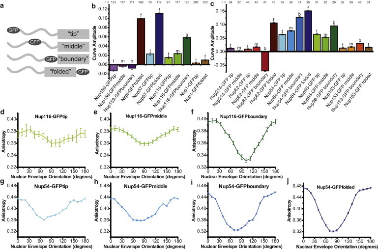
Anisotropy of Nup-GFP constructs with GFP placed at different positions along the FG domain. (a) Schematic of GFP placement relative to the FG domain. (b and c) Amplitude (r0°–r90°) of anisotropy curves: (b) Yeast and (c) mammalian constructs. Numbers of cells analyzed are shown above each bar. Homologous proteins share the same shade. Numbers of cells analyzed is shown above each bar. (d–j) Example of proteins increasing in order from tip to base of the FG domain for Yeast Nup116: (d) yNup116-GFPtip; (e) yNup116-GFPmiddle; and (f) yNup116-GFPboundary. For Mammalian Nup54: (g) mNup54-GFPtip; (h) mNup54-GFPmiddle; (i) mNup54-GFPboundary; and (j) mNup54-GFPfolded. All plots mean ± SE.
For yNup116, mNup98, yNup57, mNup54, yNsp1, and mNup62 the NE anisotropy is periodic and increased in amplitude as GFP is placed further from the tip of the FG domain (i.e., tip < middle < boundary < folded) (Fig. 2, d–j). Thus, order increases along the length of the FG domain, from tip to base.
The mNup62-GFPboundary has a Type III anisotropy curve, orienting the GFP dipole more perpendicular to the nucleocytoplasmic axis. In all other constructs, the GFP dipole is oriented more parallel to the nucleocytoplasmic axis. The GFPs at the tip and boundary of the mNup62 FG domain have opposite orientations; the orientation of the tip of the FG domain is not determined by the orientation of the base.
The absolute amplitudes of the curves vary between the proteins. For the mammalian constructs, mNup54 has the highest amplitude pattern at each position, followed by mNup98, and then mNup62. Similarly, among the yeast proteins the amplitude of the yNup57 curves is higher than that of the yNup116 and yNsp1 curves when comparing GFP placed at the same position.
The pattern of tip < middle < boundary < folded does not hold true for all the proteins. The yNup159 constructs and the mNup214 constructs show no periodicity (Fig. 1, a and f, and Fig. 2, b and c), consistent with disorder. Both yNup1constructs have similar amplitudes to each other, as do all four mNup153 constructs. yNup1 and mNup153 are the only proteins in which the boundary GFP adjacent to the coiled-coil domain does not display more order than GFP at the tip of the FG domain. Thus, the N-terminus of these proteins may be mobile or randomly oriented. These less-ordered FG nups are peripheral FG domains, whereas the ordered FG domains are in the central channel.
These patterns represent an average over many cells. We also examined the patterns present in individual yeast and mammalian cells. Some cells had strongly periodic anisotropy patterns while others were disordered. The amount of order of nups in an individual cell was not correlated to its intensity or its position in the cell cycle. The overall average order therefore arises from a spectrum of patterns present in individual cells (see Fig. S3).
Homologous FG Nups show similar amounts of order in vivo
The absolute amplitudes of the curves differ between mammalian and yeast cells, but the relative behavior of homologous proteins is similar. Nups that have increasing order from the tip to the base of the FG domain are homologous pairs (mammalian/yeast): mNup98/yNup116, mNup54/yNup57, and mNup62/yNsp1. In both organisms, mNup54/yNup57 is more ordered than mNup98/yNup116, and the folded domain of mNup54/yNup57 has a higher amplitude than that of mNup62/yNsp1. The proteins that have low amplitudes are also homologs of each other: mNup21/yNup159 and mNup153/yNup1. This indicates that order of the individual FG nups may be evolutionarily conserved, despite the low degree of sequence similarity between yeast and mammalian FG domains. This supports the idea that the observed patterns reflect functionally relevant aspects of the NPC.
FG domain behavior is dependent on position within the pore
The ordered FG nups are centrally located; the disordered FG nups are peripherally located. We tested whether behavior of the FG domains depends on their position within the NPC. We fused GFPtip-tagged FG domains from mNup98, mNup62, or mNup54 to the amino terminal side of the cytoplasmically localized mNup214 folded domain (Fig. 3). Similar domain swap experiments in yeast show that the coiled-coil domain determines the localization of the chimera (35).
Figure 3.

Moving the FG domains to a different position within the NPC causes changes in order. Anisotropy is plotted as a function of NE orientation. Schematics of the constructs are shown above graphs. (Top row) Central FG nup domains joined to the cytoplasmic Nup214 folded domain. (a) Native behavior of mNup214-GFPtip at the cytoplasmic face (purple). (b) Wild-type mNup54-GFPtip in center (blue); chimeric mNup214 coiled-coil/mNup54FG-GFPtip at the cytoplasmic face (light blue). (c) Wild-type mNup62-GFPtip in center (maroon); chimeric mNup214 coiled-coil/mNup62FG-GFPtip at the cytoplasmic face (red). (d) Wild-type mNup98-GFPtip in center (green); chimeric mNup214 coiled-coil/mNup98FG-GFPtip at the cytoplasmic face (dark green). (Middle row) Swapping FG and folded domains within a central subcomplex. (e) Native behaviors of mNup54-GFPtip (blue); mNup62-GFPtip (maroon). (f) Chimeras: mNup54 coiled-coil/mNup62FG-GFPtip (light blue); mNup62 coiled-coil/mNup54FG-GFPtip (red). (g) Native behaviors of mNup54-GFPboundary (blue); mNup62-GFPboundary (maroon). (h) Chimeras: mNup54 coiled-coil/mNup62FG-GFPboundary (light blue); mNup62 coiled-coil/mNup54FG-GFPboundary (red). (Bottom row) FG domains anchored at the plasma membrane by a palmitoyl moiety (yellow). (i) GFP-palmitoyl (black). (j) GFP-Nup54FG-palmitoyl (blue). (k) GFP-Nup62FG-palmitoyl (maroon). All plots are mean ± SE. The number of cells analyzed is indicated on each plot.
The anisotropy of mNup214-GFPtip had no dependence on NE orientation (Fig. 3 a). When the FG domains of mNup54 and mNup98 are fused to the mNup214 folded domain, GFP at the tip of the FG domain was disordered. A decrease in amplitude of mNup214/62-GFPtip relative to that of mNup62-GFPtip was difficult to detect because of the low amplitude of the mNup62-GFPtip curve (Fig. 3, b–d).
Domains that are ordered in the center of the NPC are disordered at the periphery. This result shows that the behavior of an FG nup depends on its position within the NPC. As a negative control, FG domains were artificially localized to the plasma membrane, by the addition of a C-terminal palmitoylation sequence (36), thus removing them from context of the NPC. The anisotropy of these constructs was quantified (Fig. 3, h–j) and was independent of plasma membrane orientation for the Nup54 or Nup62 FG domains. In contrast, GFP-palmitoyl alone, which is structured, was held in a defined orientation to the plasma membrane. Thus, in a cytoplasmic context, the FG domains are natively disordered, confirming that their order within the NPC is dependent on geometric constraints and/or interactions within the pore lumen. This also demonstrates that GFP tagging of the FG domain does not impose an ordered conformation on the unstructured FG domain.
FG domain behavior is influenced by local context
The order of the central FG domains may be due to only their location within the NPC, or could be influenced by local interactions. We tested this by switching the FG domains of mNup54 and mNup62, which are associated in vivo as part of the Nup62 subcomplex, but have anisotropy patterns of different amplitudes (Fig. 3 e). We created four fusion proteins: mNup54/mNup62-GFPtip; mNup62/mNup54-GFPtip; mNup54/mNup62-GFPboundary; and mNup62/mNup54-GFPboundary, where the nomenclature is “folded domain/FG domain-GFPposition”.
In all of the chimeric constructs, the anisotropy pattern was intermediate between that of mNup54 and mNup62 (Fig. 3, f–h). mNup54/62-FGtip and mNup62/54-FGtip had patterns of lower amplitude than mNup54tip and higher absolute amplitude than mNup62tip. mNup54/62-FGboundary and mNup62/54-FGboundary had a Type-I pattern (more similar to that of mNup54-GFPboundary) with a lower absolute amplitude than either that of mNup54-GFPboundary or mNup62-GFPboundary. Therefore, the degree to which the FG domain is ordered depends on the specific context around it. The pattern of the GFP at the boundary between the FG and folded domains is not simply a result of interactions between the GFP and the coiled-coil domain itself, but may be influenced by the upstream behavior of the FG domain.
The FG repeats have a limited role in FG domain behavior
Mutation of the FG repeats to AG disrupts cargo binding and FG-FG interactions in vitro (24). We investigated the effect of these mutations in vivo. FG to AG mutations had no effect on the anisotropy of the mNup62 constructs (Fig. 4); mNup62 organization is therefore not dependent on the mNup62 FG repeats.
Figure 4.
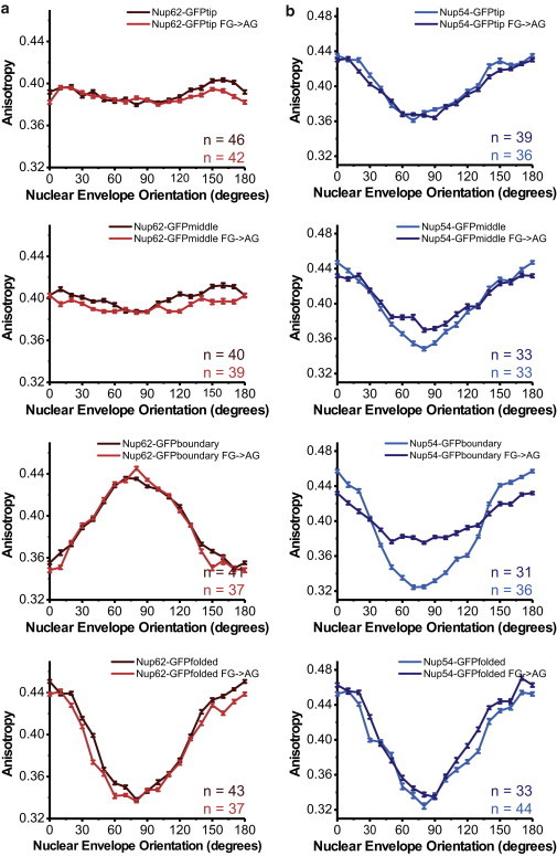
Contribution of FG repeats to ordering. Anisotropy is plotted as a function of NE orientation for wild-type and mutant FG→AG constructs. (a) mNup62-GFP constructs (top to bottom): tip, middle, boundary, folded; WT (maroon, gray in print) and FG→AG mutant (red, gray in print). (b) mNup54-GFP constructs (top to bottom): tip, middle, boundary, folded; WT (blue, gray in print) and FG→AG mutant (dark blue, dark gray in print). All plots are mean ± SE. The number of cells analyzed is indicated on each plot.
There was no effect of altering the FG repeats to AG on the anisotropy pattern of mNup54-GFPtip or mNup54-GFPfolded. The anisotropy patterns of mNup54-GFPmiddle and mNup54-GFPboundary decreased in amplitude but were still periodic, with a Type-I pattern (Fig. 4 b). The order is partially affected but not completely lost, indicating some organization of some sections of mNup54 depends on the FG repeats.
When the FG repeats of mNup98 were mutated to AG, the protein was not at the NE but instead localized to the cytoplasm (see Fig. S4). The FG domain of mNup98 is required for its localization (37); these data show that the FG repeats are at least partially necessary for Nup98 targeting (see Fig. S4).
Anisotropy measurements can detect protein binding
The FG domains of mNup62, mNup98, mNup214, mNup153, and mNup54 are modified by O-linked glycosyl groups, which bind the lectin wheat germ agglutinin (WGA); this allows cargo binding but prevents transport (38,39). It is hypothesized that this is due to crosslinking and immobilization of the FG nups.
To test whether WGA binding affects ordering of the FG domains, cells were permeabilized (see Fig. S5) and WGA was added. WGA caused no changes in the anisotropy of mNup54 and mNup62 constructs with GFP at the tip, middle, or folded domain. However, the anisotropy patterns of mNup54-GFPboundary and mNup62-GFPboundary decreased in amplitude, indicating an increase in disorder (Fig. 5). Therefore, the effects of protein binding to pore components can be detected in this assay. The glycosylation sites in mNup62 are predicted to lie in-between the FG repeats and the folded domain; WGA binding may only affect protein structure close to the glycosylation sites.
Figure 5.

Ligand binding can be detected in anisotropy measurements. (a) Schematic of mNup54 (left) and mNup62 (right) with putative glycosylated regions (yellow diamonds). Position of the FG repeats relative to the glycosylated region is shown. (b and c) Anisotropy plotted against NE orientation. Each plot shows a nucleoporin-GFP mock- and WGA-treated. (b) mNup54-GFP constructs (top to bottom): tip, middle, boundary, folded. Mock treatment (dark blue, light gray in print); WGA treatment (light blue, gray in print). (c) mNup62-GFP constructs (top to bottom): tip, middle, boundary, folded. Mock treatment (maroon, light gray in print); WGA treatment (red, gray in print). All plots are mean ± SE.
WGA had no effect on the anisotropy of the mNup98, mNup214, and mNup153 constructs (see Fig. S5). If the glycosyl groups within these domains are not located close to GFP, perturbations caused by WGA might not be transmitted to the rest of the domain and would not be detectable as a change in anisotropy.
FG domain behavior is independent of active transport
To determine whether active transport of cargo affects FG nup behavior, we stopped active transport in yeast by disrupting the RanGTP gradient using azide and deoxyglucose treatment (40). Transport was assayed with mCherry-NLS (Fig. 6 a).
Figure 6.

Active transport and cargo binding have no effect on anisotropy. (a) Azide and deoxyglucose transport block monitored by mCherry-NLS. Accumulation of fluorescence in the nucleus is indicative of active transport. (b) Average ratio of anisotropy values for azide-treated/control yeast cells ± SD. (c) Standard deviation of average anisotropy ratio for azide-treated/control yeast cells. Smaller standard deviations indicate more similar values between the two conditions at all orientation points on the anisotropy curves. (d) Characteristic examples of Kapβ-GFP unbinding in control cells (top three panels) and RanGTP-treated cells (bottom three panels). Nup62-mCherry is a marker for the NE and a control for fluorescence loss caused by photobleaching. Data from multiple cells was averaged and is shown in panel e. (e) Normalized average NE fluorescence ± SD for kapβ-GFP and mNup62-mCherry in RanGTP-treated and control cells. (f) Average % NE fluorescence remaining ± SD 10 min after mock treatment or RanGTP. (g) Average ratio of anisotropy values for RanGTP-treated/control HeLa cells ± SD. (h) Standard deviation of average anisotropy ratio for RanGTP-treated/control HeLa cells.
The anisotropies of yNup57-GFPtip, yNup57-GFPfolded, yNup116-GFPtip, yNup116-GFPmiddle, yNup116-GFPboundary, yNup159-GFPtip, yNup159-GFPmiddle, and yNup159-GFPboundary were not affected by transport block (Fig. 6, b and c, and see Fig. S6); FG domain ordering is not dependent on active transport. This is consistent with no effect of permeabilization on anisotropy in mammalian cells, as permeabilization also disrupts the Ran gradient (see Fig. S5).
Cargo binding has no effect on FG nup behavior
Although transport is stopped upon depletion of RanGTP, cargo may still be bound, which could affect FG domain behavior. To test this we expressed karyopherinβ1-GFP (kapβ1-GFP) with Nup62-mCherry as a NE marker. Kapβ1 is used as a proxy for cargo load as it transports a wide range of molecules into the nucleus. In control cells, kapβ1-GFP is present in the cytoplasm and enriched at the NE. The cytoplasmic kapβ1-GFP signal is lost in permeabilized cells but NE fluorescence remains longer than 30 min, showing cargo bound at the NPC. To unbind the cargo, we added RanGTP. Most kapβ1-GFP unbound in the first 5 min after RanGTP addition (Fig. 6, e and f). 10 min after RanGTP addition (0.3 mg/mL) the GFP signal at the NE had decreased to 43% compared to 80% in control cells (Fig. 6 d). However, there was no effect of kapβ1-GFP dissociation on the anisotropy of the mNup54, mNup62, mNup98, mNup214, or mNup153 constructs (Fig. 6, g and h, and see Fig. S6). Reducing the bound kapβ1 by more than 50% has no effect on the organization and behavior of the FG nucleoporins.
Discussion
Each FG domain has a unique behavior in vivo, and many adopt specific orientational order. Importantly, the relative amount of order is conserved between homologous yeast and mammalian FG nups. Thus, the behavior of individual nucleoporins within the NPC may have relevance for function. These observations will be critical in interpreting models and furthering understanding of nuclear transport.
FG domains are unfolded but ordered
In vitro FG domains are in an unfolded conformation (41), and linker regions between FG repeats are poorly conserved, suggesting that they are not important for formation of secondary structural elements (13). This is consistent with our observation that different portions of the FG domain can behave independently of one another, consistent with a lack of fixed structure. However, we show that unstructured domains are organized within the NPC in an oriented manner.
We do not think the GFP tag is affecting the orientational behavior of the FG domains. The identity of the FG nup tagged has a strong impact on behavior, suggesting that the measurements reflect differences between the FG domains themselves. Additionally, tests with an alternative fluorescent marker are consistent with the results observed for GFP (see Fig. S1).
FG domains in the context of the NPC
Packing a high density of unfolded protein domains within the pore lumen may cause alignment in a preferred orientation, explaining the central FG domain order. The peripheral FG domains are disordered, consistent with their less constrained geometry. The organization of these domains is not intrinsic but depends on positioning and interactions within the NPC.
The GFP dipoles at the tips and middles of the ordered FG domains are oriented in the same direction, more parallel than perpendicular to the nucleocytoplasmic axis. The orientation of GFP relative to the FG domain is unknown; if all GFP molecules are oriented in the same way to the FG domains, this suggests that the FG domains may all be oriented in the same direction.
For central FG domains, we observe an increase in order from tip to base, consistent with an anchored filament. If extended, many FG domains are longer than the channel width, and would have to be extended along the nucleo-cytoplasmic axis. Such extended FG domains have been observed in EM (42); FG domains in an extended conformation aligned along the nucleocytoplasmic axis was recently proposed for mNup54 and mNup62 (43).
Behavior of individual FG domains
The anisotropy patterns are a spatio-temporal average of many GFP molecules. It is critical to note that the fluorescence lifetime of GFP is ∼3 ns, transport events are 1–2 ms, and our exposure times are 2000 ms. We are measuring protein properties during several thousand transport events, therefore preferred orientations of an overall population of FG nups are measured. Because of these differences in timescale, changes in orientation of an individual protein during a single transport event cannot be detected (see Note in the Supporting Material). The anisotropy pattern alone is not enough to distinguish between static and dynamic organization for averaged data. The observed low amplitude curves for GFP at the tip or middle of the FG domains (Fig. 2, b and c) could arise if every GFP molecule is held statically in certain specific orientations (30), but a more likely explanation is that low amplitude patterns result from many GFP molecules in a range of orientations. This would be compatible with the idea that FG domains are mobile, but spend more time in one orientation than the other, leading to an ordered pattern on average. Thus, the FG nups may be dynamic with a particular orientation or conformation preferred.
Implications for models for nucleocytoplasmic transport
These data are compatible with many previous observations, but rule out some aspects of the existing models. The order of the central FG domains suggests limitations to the space they are exploring, in contrast to models where FG domains are completely free to move according to entropy (7). However, the FG domains still could be mobile. Particular FG domains are ordered even if their ability to make FG-FG interactions is disrupted by mutating FG motifs, which suggests that order is not coming from participation of the FG domain in a saturated polymer gel (the hydrophobic gel model) (15).
Many models for transport treat the FG domains as interchangeable components of a homogenous network; our data show that they have distinct behaviors in situ. Interestingly, a recent study in which the Stokes radii of purified FG domains were determined showed that some domains are collapsed coils, while others are extended (25). Interestingly, Nup57, which has the most ordered tip of the yeast nups, is predicted to adopt a collapsed coil proximal to the pore wall, whereas Nup159, for which we measure less order at the tip, is predicted to adopt an extended conformation. However, the relationship does not hold up in every case, because in solution Nup1 is predicted to have a cohesive, collapsed coil at the N-terminus, but does not show an ordered pattern in vivo. This shows the importance of in situ context for FG domain behavior. The study also suggests that FG domains interact differently depending on their nonFG amino acid content; this is in keeping with our observation that FG repeats are not the primary determinant of FG domain order.
Rounds of cargo binding and unbinding to the FG nups are invoked in several models of nucleocytoplasmic transport. We observed import cargo at the NE for >30 min after permeabilization, and a requirement for RanGTP for unbinding. This is probably incompatible with cargo rapidly binding and unbinding, as one would expect cargo to be lost by unbinding and diffusion away from the NPC in this scenario. Single-molecule studies have suggested that Ran acts exclusively to unbind cargo at the nuclear face (44), which is compatible with a Brownian ratchet model for transport (21). In contrast to in vitro observations that FG domains form an extended polymer brush that collapses when cargo binds, we detected no gross conformational change in vivo when import cargo was purged from the NPC.
Conclusion
Nematic ordering of the FG domains
A speculative cartoon, to aid visualizations for ordering within the NPC, is presented in Fig. 7. The behavior of each FG domain is uniquely determined by its biophysical properties and interactions with its surroundings (Fig. 7 a). Although individual domains adopt many conformations, geometric constraints require the majority of central FG domains to align, orienting them with respect to the NPC (Fig. 7 b). For some proteins, such as mNup54, this overall organization is reinforced by interactions via the FG repeats.
Figure 7.

Speculative model for order of FG domains within the NPC. Different FG domains are shown as different colored ribbons. (a) Each FG domain has a unique order within the NPC depending on its properties and interactions. FG domains of the central nups increase in order from tip to base (gray arrows). (b) Dense packing of the central FG domains within NPC lumen results in their overall alignment. This alignment is characterized by overall orientational, but not positional, ordering. Individual FG domains can adopt multiple conformations but average orientation (black arrow) is maintained. (c) Peripheral FG domains have more freedom in the space they can explore. These domains are disordered on average. (d) Speculative model for Brownian ratchet cargo transport mechanism. Dense packing of the FG domains (gray ribbons) sterically prevents nonspecific molecules from entering (orange). Cargo bound to a karyopherin (purple) can recognize and bind FG repeats (1), allowing it to enter. The FG domain to which it is bound (green) changes conformation and moves across the NPC lumen (2). Cargo is released by RanGTP binding inside the nucleus (3).
Ordering of the central FG domains is nematic, characterized by orientational order along the nucleocytoplasmic axis without implications for positional order. Other biological examples of nematic order are fatty acid tails organized in a membrane, and viral DNA packed into the capsid. In contrast, at the periphery of the NPC, the FG domains are less constrained in the space they can explore, and are disordered (Fig. 7 c).
Dense packing of FG domains into the lumen of the pore provides a mechanism for cargo specificity by sterically blocking nonspecific cargo from the NPC while molecules that bind FG repeats can enter (Fig. 7 d). Import cargo remains bound to the FG domain until it encounters RanGTP, supporting a Brownian ratchet model for transport (21).
To our knowledge, these experiments are the first extensive measurements of FG domain behavior in situ in both mammalian and yeast cells, and reveal an unexpected degree of order within the NPC. This order of the FG domains is best understood in the constraints of the local geometry of the central channel of the NPC, and has important implications for the mechanism of cargo transport through the NPC.
Acknowledgments
We thank Günter Blobel, Elias Coutavas, and Susan Wente for plasmids, Sozanne Solmaz and Marina Fix for assistance with Ran purification, and Joe Osmundson for critical discussion of the manuscript.
This research was supported by National Institutes of Health grant No. GM087977 to S.M.S.
Footnotes
Alexa L. Mattheyses’s present address is Department of Cell Biology, Emory University School of Medicine, Atlanta, GA.
Martin Kampmann’s present address is Department of Cellular and Molecular Pharmacology, University of California at San Francisco, San Francisco, CA.
Claire E. Atkinson's present address is Department of Biochemistry and Molecular Biology, University of Chicago, Chicago, IL.
This is an Open Access article distributed under the terms of the Creative Commons-Attribution Noncommercial License (http://creativecommons.org/licenses/by-nc/2.0/), which permits unrestricted noncommercial use, distribution, and reproduction in any medium, provided the original work is properly cited.
Supporting Material
References
- 1.Ryan K.J., Wente S.R. The nuclear pore complex: a protein machine bridging the nucleus and cytoplasm. Curr. Opin. Cell Biol. 2000;12:361–371. doi: 10.1016/s0955-0674(00)00101-0. [DOI] [PubMed] [Google Scholar]
- 2.Melchior F., Paschal B., Gerace L. Inhibition of nuclear protein import by nonhydrolyzable analogues of GTP and identification of the small GTPase Ran/TC4 as an essential transport factor. J. Cell Biol. 1993;123:1649–1659. doi: 10.1083/jcb.123.6.1649. [DOI] [PMC free article] [PubMed] [Google Scholar]
- 3.Moore M.S., Blobel G. The GTP-binding protein Ran/TC4 is required for protein import into the nucleus. Nature. 1993;365:661–663. doi: 10.1038/365661a0. [DOI] [PubMed] [Google Scholar]
- 4.Bischoff F.R., Ponstingl H. Catalysis of guanine nucleotide exchange on Ran by the mitotic regulator RCC1. Nature. 1991;354:80–82. doi: 10.1038/354080a0. [DOI] [PubMed] [Google Scholar]
- 5.Moroianu J., Blobel G. Protein export from the nucleus requires the GTPase Ran and GTP hydrolysis. Proc. Natl. Acad. Sci. USA. 1995;92:4318–4322. doi: 10.1073/pnas.92.10.4318. [DOI] [PMC free article] [PubMed] [Google Scholar]
- 6.Bischoff F.R., Klebe C., Ponstingl H. RanGAP1 induces GTPase activity of nuclear Ras-related Ran. Proc. Natl. Acad. Sci. USA. 1994;91:2587–2591. doi: 10.1073/pnas.91.7.2587. [DOI] [PMC free article] [PubMed] [Google Scholar]
- 7.Rout M.P., Aitchison J.D., Chait B.T. Virtual gating and nuclear transport: the hole picture. Trends Cell Biol. 2003;13:622–628. doi: 10.1016/j.tcb.2003.10.007. [DOI] [PubMed] [Google Scholar]
- 8.Wente S.R., Rout M.P., Blobel G. A new family of yeast nuclear pore complex proteins. J. Cell Biol. 1992;119:705–723. doi: 10.1083/jcb.119.4.705. [DOI] [PMC free article] [PubMed] [Google Scholar]
- 9.Bayliss R., Ribbeck K., Stewart M. Interaction between NTF2 and xFxFG-containing nucleoporins is required to mediate nuclear import of RanGDP. J. Mol. Biol. 1999;293:579–593. doi: 10.1006/jmbi.1999.3166. [DOI] [PubMed] [Google Scholar]
- 10.Bayliss R., Littlewood T., Stewart M. Structural basis for the interaction between FxFG nucleoporin repeats and importin-β in nuclear trafficking. Cell. 2000;102:99–108. doi: 10.1016/s0092-8674(00)00014-3. [DOI] [PubMed] [Google Scholar]
- 11.Feldherr C.M., Akin D. The location of the transport gate in the nuclear pore complex. J. Cell Sci. 1997;110:3065–3070. doi: 10.1242/jcs.110.24.3065. [DOI] [PubMed] [Google Scholar]
- 12.Terry L.J., Wente S.R. Flexible gates: dynamic topologies and functions for FG nucleoporins in nucleocytoplasmic transport. Eukaryot. Cell. 2009;8:1814–1827. doi: 10.1128/EC.00225-09. [DOI] [PMC free article] [PubMed] [Google Scholar]
- 13.Denning D.P., Rexach M.F. Rapid evolution exposes the boundaries of domain structure and function in natively unfolded FG nucleoporins. Mol. Cell. Proteomics. 2007;6:272–282. doi: 10.1074/mcp.M600309-MCP200. [DOI] [PubMed] [Google Scholar]
- 14.Peters R. Translocation through the nuclear pore: kaps pave the way. Bioessays. 2009;31:466–477. doi: 10.1002/bies.200800159. [DOI] [PubMed] [Google Scholar]
- 15.Frey S., Görlich D. A saturated FG-repeat hydrogel can reproduce the permeability properties of nuclear pore complexes. Cell. 2007;130:512–523. doi: 10.1016/j.cell.2007.06.024. [DOI] [PubMed] [Google Scholar]
- 16.Frey S., Görlich D. FG/FxFG as well as GLFG repeats form a selective permeability barrier with self-healing properties. EMBO J. 2009;28:2554–2567. doi: 10.1038/emboj.2009.199. [DOI] [PMC free article] [PubMed] [Google Scholar]
- 17.Peters R. Translocation through the nuclear pore complex: selectivity and speed by reduction-of-dimensionality. Traffic. 2005;6:421–427. doi: 10.1111/j.1600-0854.2005.00287.x. [DOI] [PubMed] [Google Scholar]
- 18.Reference deleted in proof.
- 19.Timney B.L., Tetenbaum-Novatt J., Rout M.P. Simple kinetic relationships and nonspecific competition govern nuclear import rates in vivo. J. Cell Biol. 2006;175:579–593. doi: 10.1083/jcb.200608141. [DOI] [PMC free article] [PubMed] [Google Scholar]
- 20.Jovanovic-Talisman T., Tetenbaum-Novatt J., Chait B.T. Artificial nanopores that mimic the transport selectivity of the nuclear pore complex. Nature. 2009;457:1023–1027. doi: 10.1038/nature07600. [DOI] [PMC free article] [PubMed] [Google Scholar]
- 21.Mincer J.S., Simon S.M. Simulations of nuclear pore transport yield mechanistic insights and quantitative predictions. Proc. Natl. Acad. Sci. USA. 2011;108:E351–E358. doi: 10.1073/pnas.1104521108. [DOI] [PMC free article] [PubMed] [Google Scholar]
- 22.Lim R.Y.H., Huang N.-P., Aebi U. Flexible phenylalanine-glycine nucleoporins as entropic barriers to nucleocytoplasmic transport. Proc. Natl. Acad. Sci. USA. 2006;103:9512–9517. doi: 10.1073/pnas.0603521103. [DOI] [PMC free article] [PubMed] [Google Scholar]
- 23.Lim R.Y.H., Fahrenkrog B., Aebi U. Nanomechanical basis of selective gating by the nuclear pore complex. Science. 2007;318:640–643. doi: 10.1126/science.1145980. [DOI] [PubMed] [Google Scholar]
- 24.Patel S.S., Belmont B.J., Rexach M.F. Natively unfolded nucleoporins gate protein diffusion across the nuclear pore complex. Cell. 2007;129:83–96. doi: 10.1016/j.cell.2007.01.044. [DOI] [PubMed] [Google Scholar]
- 25.Yamada J., Phillips J.L., Rexach M.F. A bimodal distribution of two distinct categories of intrinsically disordered structures with separate functions in FG nucleoporins. Mol. Cell. Proteomics. 2010;9:2205–2224. doi: 10.1074/mcp.M000035-MCP201. [DOI] [PMC free article] [PubMed] [Google Scholar]
- 26.Axelrod D. Carbocyanine dye orientation in red cell membrane studied by microscopic fluorescence polarization. Biophys. J. 1979;26:557–573. doi: 10.1016/S0006-3495(79)85271-6. [DOI] [PMC free article] [PubMed] [Google Scholar]
- 27.Rocheleau J.V., Edidin M., Piston D.W. Intrasequence GFP in class I MHC molecules, a rigid probe for fluorescence anisotropy measurements of the membrane environment. Biophys. J. 2003;84:4078–4086. doi: 10.1016/S0006-3495(03)75133-9. [DOI] [PMC free article] [PubMed] [Google Scholar]
- 28.Vrabioiu A.M., Mitchison T.J. Symmetry of septin hourglass and ring structures. J. Mol. Biol. 2007;372:37–49. doi: 10.1016/j.jmb.2007.05.100. [DOI] [PubMed] [Google Scholar]
- 29.Mattheyses A.L., Kampmann M., Simon S.M. Fluorescence anisotropy reveals order and disorder of protein domains in the nuclear pore complex. Biophys. J. 2010;99:1706–1717. doi: 10.1016/j.bpj.2010.06.075. [DOI] [PMC free article] [PubMed] [Google Scholar]
- 30.Kampmann M., Atkinson C.E., Simon S.M. Mapping the orientation of nuclear pore proteins in living cells with polarized fluorescence microscopy. Nat. Struct. Mol. Biol. 2011;18:643–649. doi: 10.1038/nsmb.2056. [DOI] [PMC free article] [PubMed] [Google Scholar]
- 31.Maimon T., Elad N., Medalia O. The human nuclear pore complex as revealed by cryo-electron tomography. Structure. 2012;20:998–1006. doi: 10.1016/j.str.2012.03.025. [DOI] [PubMed] [Google Scholar]
- 32.Fernandez-Martinez J., Phillips J., Rout M.P. Structure-function mapping of a heptameric module in the nuclear pore complex. J. Cell Biol. 2012;196:419–434. doi: 10.1083/jcb.201109008. [DOI] [PMC free article] [PubMed] [Google Scholar]
- 33.Thorn K. Optimized cassettes for fluorescent protein tagging in Saccharomyces cerevisiae. Yeast. 2004;21:661–670. doi: 10.1002/yea.1130. [DOI] [PubMed] [Google Scholar]
- 34.Herskowitz I. Life cycle of the budding yeast Saccharomyces cerevisiae. Microbiol. Rev. 1988;52:536–553. doi: 10.1128/mr.52.4.536-553.1988. [DOI] [PMC free article] [PubMed] [Google Scholar]
- 35.Zeitler B., Weis K. The FG-repeat asymmetry of the nuclear pore complex is dispensable for bulk nucleocytoplasmic transport in vivo. J. Cell Biol. 2004;167:583–590. doi: 10.1083/jcb.200407156. [DOI] [PMC free article] [PubMed] [Google Scholar]
- 36.El-Husseini A.-D., Craven S.E., Bredt D.S. Polarized targeting of peripheral membrane proteins in neurons. J. Biol. Chem. 2001;276:44984–44992. doi: 10.1074/jbc.M103049200. [DOI] [PubMed] [Google Scholar]
- 37.Griffis E.R., Altan N., Powers M.A. Nup98 is a mobile nucleoporin with transcription-dependent dynamics. Mol. Biol. Cell. 2002;13:1282–1297. doi: 10.1091/mbc.01-11-0538. [DOI] [PMC free article] [PubMed] [Google Scholar]
- 38.Finlay D.R., Newmeyer D.D., Forbes D.J. Inhibition of in vitro nuclear transport by a lectin that binds to nuclear pores. J. Cell Biol. 1987;104:189–200. doi: 10.1083/jcb.104.2.189. [DOI] [PMC free article] [PubMed] [Google Scholar]
- 39.Newmeyer D.D., Forbes D.J. Nuclear import can be separated into distinct steps in vitro: nuclear pore binding and translocation. Cell. 1988;52:641–653. doi: 10.1016/0092-8674(88)90402-3. [DOI] [PubMed] [Google Scholar]
- 40.Shulga N., Roberts P., Goldfarb D.S. In vivo nuclear transport kinetics in Saccharomyces cerevisiae: a role for heat shock protein 70 during targeting and translocation. J. Cell Biol. 1996;135:329–339. doi: 10.1083/jcb.135.2.329. [DOI] [PMC free article] [PubMed] [Google Scholar]
- 41.Denning D.P., Patel S.S., Rexach M. Disorder in the nuclear pore complex: the FG repeat regions of nucleoporins are natively unfolded. Proc. Natl. Acad. Sci. USA. 2003;100:2450–2455. doi: 10.1073/pnas.0437902100. [DOI] [PMC free article] [PubMed] [Google Scholar]
- 42.Chatel G., Desai S.H., Fahrenkrog B. Domain topology of nucleoporin Nup98 within the nuclear pore complex. J. Struct. Biol. 2012;177:81–89. doi: 10.1016/j.jsb.2011.11.004. [DOI] [PMC free article] [PubMed] [Google Scholar]
- 43.Solmaz S.R., Chauhan R., Melčák I. Molecular architecture of the transport channel of the nuclear pore complex. Cell. 2011;147:590–602. doi: 10.1016/j.cell.2011.09.034. [DOI] [PMC free article] [PubMed] [Google Scholar]
- 44.Lowe A.R., Siegel J.J., Liphardt J.T. Selectivity mechanism of the nuclear pore complex characterized by single cargo tracking. Nature. 2010;467:600–603. doi: 10.1038/nature09285. [DOI] [PMC free article] [PubMed] [Google Scholar]
- 45.Coppin C.M., Leavis P.C. Quantitation of liquid-crystalline ordering in F-actin solutions. Biophys. J. 1992;63:794–807. doi: 10.1016/S0006-3495(92)81647-8. [DOI] [PMC free article] [PubMed] [Google Scholar]
- 46.Oskolkov N.N., Linse P., Khokhlov A.R. Nematic ordering of polymers in confined geometry applied to DNA packaging in viral capsids. J. Phys. Chem. B. 2011;115:422–432. doi: 10.1021/jp108461z. [DOI] [PubMed] [Google Scholar]
Associated Data
This section collects any data citations, data availability statements, or supplementary materials included in this article.