Abstract
Introduction
This paper shows the influence of a measurement method of features in the diagnosis of Hashimoto’s disease. Sensitivity of the algorithm to changes in the parameters of the ROI, namely shift, resizing and rotation, has been presented. The obtained results were also compared to the methods known from the literature in which decision trees or average gray level thresholding are used.
Material
In the study, 288 images obtained from patients with Hashimoto’s disease and 236 images from healthy subjects have been analyzed. For each person, an ultrasound examination of the left and right thyroid lobe in transverse and longitudinal sections has been performed.
Method
With the use of the developed algorithm, a discriminant analysis has been conducted for the following five options: linear, diaglinear, quadratic, diagquadratic and mahalanobis. The left and right thyroid lobes have been analyzed both together and separately in transverse and longitudinal sections. In addition, the algorithm enabled to analyze specificity and sensitivity as well as the impact of sensitivity of ROI shift, repositioning and rotation on the measured features.
Results and summary
The analysis has shown that the highest accuracy was obtained for the longitudinal section (LD) with the method of linear, yielding sensitivity = 76%, specificity = 95% and accuracy ACC = 84%. The conducted sensitivity assessment confirms that changes in the position and size of the ROI have little effect on sensitivity and specificity. The analysis of all cases, that is, images of the left and right thyroid lobes in transverse and longitudinal sections, has shown specificity ranging from 60% to 95% and sensitivity from 62% to 89%. Additionally, it was shown that the value of ACC for the method using decision trees as a classifier is equal to 84% for the analyzed data. Thresholding of average brightness of the ROI gave ACC equal to 76%.
Keywords: Image processing, Hashimoto, Thyroid, Ultrasonograms
Introduction
The measurement of thyroid echogenicity is currently one of the most common and standardly performed measurements in ultrasound diagnosis. Measurements of this type have evolved over the years in accordance with progress and increase in the quality of ultrasound equipment. In the beginning [1-4], qualitative evaluation methods related to the areas of analysis and methods of description were explained. At that time, it was proved that normal thyroid echogenicity is higher than that of sternocleidomastoid and subhyoid muscles. Later, this approach was extended and the salivary gland was included in the analysis [5]. With advances in computer technology and capabilities of digital recording and analysis, first papers on quantitative measurements [6-9] appeared. Those measurements were related to the use of basic methods of image analysis and processing in the diagnosis of, for example, Hashimoto’s disease [10,11]. Due to imperfections introduced by the measurement method (scanning ultrasound pictures), this methodology has not been adopted in clinical practice. Scanning as well as other processes of non-digital image analysis introduce a significant error of the method and are not repeatable. The next stage were the methods of digital images analysis which ensured repeatability of measurement. They are mainly presented in Mailloux’s papers from the years 1984 to 1986 [12-14]. Those papers concern the application of texture analysis in ultrasound images. Nowadays, there are modern methods of analysis of ultrasound images. Although they are virtually limitless, there is still no clear method of disk image analysis that would give reproducible and unambiguous results. Many authors now attempt to use morphological and statistical methods in the analysis of texture of the thyroid lobe. In those methods, both the analysis of histograms, which gives partially correct results, as well as more advanced methods of texture analysis are used. These are, for example, methods [15,16] which are based on the analysis of the areas indicated by the operator. The areas are analyzed by Co-occurrence Matrices. Then, Haralick’s coefficients are determined. The analysis of the Radon Domain [17] or Fuzzifying the Local Binary Patterns [18,19] are further examples of the afore-mentioned methods. In recent works, an approach based on Support Vector Machines [20-22] can also be found. The results obtained using the Bayes classifier [23] or Gaussian mixture model [24] are interesting as well. In the literature, there are also other approaches to texture analysis, such as neural networks [25,26] other [27-33] or dissertation [34]. The methods of image analysis presented in those works need to be profiled to a specific application every time they are used. However, valuable evidence related to the measurement method and rough interpretation of ultrasound images of the thyroid arise from those works. For example, it was found that it is best to set the instrument to 10 MHz to achieve accuracy of results; the cut-off point is -69dB for Hashimoto’s disease [35,36]. The authors of papers [37,38] showed advanced methods of texture analysis of thyroid lobe images. Those methods were shaped to the diagnosis of Hashimoto’s disease. In paper [39], it was proved that only three of the ten features measured in an image are enough for a correct assessment of Hashimoto’s disease. These three features will be the basis of analysis in this paper.
Material
In this paper, the examined group were:
― 59 healthy subjects aged 18 to 60,
― 73 patients with Hashimoto’s disease
The images were obtained with GE Logiq P5 ultrasound machine. The frequency of the transmitter was set to 10 MHz, and harmonic imaging option was turned off. All the images were recorded in DICOM format. During the test, the patient remained in the supine position and the doctor applied ultrasound heads to the right and left side of the thyroid.
For each subject, four ultrasound images were taken. Those were images of the right and left lobe of the thyroid in both transverse and longitudinal section. Due to thick errors caused by improperly performed acquisition, 288 images from patients with Hashimoto’s disease and 236 images from healthy subjects were further analyzed. The examined group was divided in equal proportions into learning, validation and test groups. Each ultrasound image was analyzed in great detail and, then, an expert physician selected for analysis a rectangular region (ROI) which covered the thyroid lobe in individual sections. Each time, the ROI included the greatest possible and most representative area of the patient’s thyroid lobe.
Method
Preliminary image analysis
LGRAY input images were obtained from GE ultrasound machine with a resolution of MG×NG=614×816 pixels. The first stage of image preprocessing was filtration done with the use of a median filter whose mask size is Mh×Nh=3×3. The filtered images LMED were further used in subsequent stages of image analysis and processing. In the images (taken in transverse and longitudinal sections of the right and left thyroid lobe), an expert physician selected a rectangular area of analysis. Papers [37] and [38] describe an automated way of selecting this area of the thyroid, but only in transverse sections. The basis for its operation is a clearly visible artery calibrating the recognition system. The manually marked area of the thyroid lobe LS with a resolution of Ms×Ns was analyzed. The results of the analysis are shown below.
The measured image features
The analysis of the thyroid lobe as texture in paper [39] proved that only 3 out of 10 different features are reliable in the assessment of Hashimoto’s disease. These features are: smoothness- w(1), minimum brightness after removing noise- w(2) and the percentage number of areas 8×8 in the square-tree decomposition- w(3). The ways to calculate individual values of the features are discussed in detail below:
w(1) – smoothness
| (1) |
where wSTD
| (2) |
Smoothness defined by the formula (1) is relatively easy to interpret because it is a standardized measure based on a standard deviation of the mean.
w(2) – the minimum value of brightness in the image Ls after removing all the pixels whose number for a given brightness is less than 20% of the largest number of brightness pixels, i.e.:
| (3) |
where
| (4) |
for i=1,2,3,…,254,255.
| (5) |
where
| (6) |
| (7) |
On the basis of pre-tests and preliminary analyses, a noise threshold of 0.2 was set. The value of i* formulated in this way constitutes another feature, i.e. w(2).
w(3) – percentage of instances of areas 8×8 obtained for the 10% threshold as a result of a square-tree decomposition.
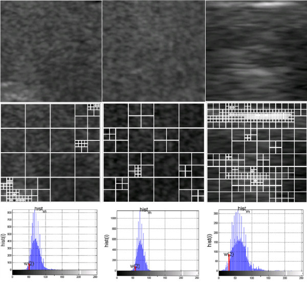
A square-tree decomposition [39,40] enables to determine some statistical characteristics of the image. In this case, these are areas of 8×8 resulting from a division of the image Ls. Their number is a measure of the feature w(3). The thyroid image LS with a resolution of Ms×Ns is divided into “i” rectangular areas Li with a resolution of Mi×Ni for the "i" coefficient value in the range 1<=i<=I. These areas can also have different sizes, i.e. 1×1, and the largest - Ms×Ns pixels. However, for the adopted definition of the feature w(3) and the analyses carried out in [21], only the areas of 8×8 pixels are relevant. The 10% brightness threshold, which is the criterion of division into other smaller areas, was chosen on the basis of preliminary measurements and analyses of Ls image content [21]. An example of a division is shown in Figure 1. The values of the feature w(3) are calculated as a percentage relative to the whole image.
Figure 1.
Examples of textures of the thyroid lobes with images showing the square-tree division and a histogram with the value of the feature w(2). For the presented images, there are values of the features w(1), w(2), w(3) - for the first column w(1)=0.0025, w(2)=51, w(3)=26.17, for the second column w(1)=0.0013, w(2)=58, w(3)=33.98 and for the third column w(1)=0.0081, w(2)=33, w(3)=15.67.
The features w(1) to w(3) are the basis for further analysis.
Results
A qualitative assessment of the measurement of echogenicity and its impact on the results obtained in the classification of Hashimoto’s disease was conducted using a statistical approach [41,42]. A discriminant analysis was used for the following five options:
linear- linear discriminant analysis,
diaglinear- linear discriminant analysis but with a diagonal covariance matrix estimate (naive Bayes classifiers),
quadratic- quadratic discriminant analysis,
diagquadratic- quadratic discriminant analysis but with a diagonal covariance matrix estimate (naive Bayes classifiers),
mahalanobis- using the distance Mahalanobis with stratified covariance estimates.
It was assumed that the discriminatory variables w(1), w(2), w(3) represent a three-dimensional normal distribution (although previous studies carried out with the use of multivariate discriminant functions confirm the correctness of the classification, even in violation of this assumption). Divisibility of the variables is retained. This divisibility is reflected in the systematic difference in mean values between groups. Also the equality of covariance matrices is preserved. Empirical studies show that the assumption of equal group covariance matrices can be omitted.
These specific types of discriminant analysis were used to classify patients from healthy subjects. Assuming the classification results in terms of the following results: TP- true positive, TN- true negative, FP- false positive, FN- false negative, sensitivity was defined as TPR = TP / (TP + FN) and specificity as SPC = TN / (FP + TN). In addition, the analysis was performed for the following groups of data:
LO– images of the left transverse section of the thyroid,
RO– images of the right transverse section of the thyroid,
LRO– images of the left and right transverse sections of the thyroid,
RD– images of the right longitudinal section of the thyroid,
LD– images of the left longitudinal section of the thyroid,
RLD– images of the right and left longitudinal section of the thyroid,
RLOD– images of the right and left transverse and longitudinal sections of the thyroid.
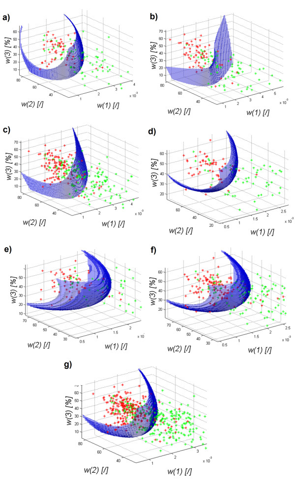
The results obtained for the discriminant analysis - quadratic discriminant analysis – are shown in Figure 2a) to g).
Figure 2.
The graph of the decision function for classification (quadratic) of healthy subjects (red) from patients (green) depending on the features w (1), w (2) and w(3) for the images of the: a) left transverse section of the thyroid LO, b) right transverse section of the thyroid RO, c) left and right transverse sections of the thyroid LRO, d) left longitudinal section of the thyroid LD, e) right longitudinal section of the thyroid RD, f) left and right longitudinal sections of the thyroid RLD, g) left and right transverse and longitudinal sections of the thyroid LROD. The decision function was selected automatically and the classification gave the following results: graph a) specificity at 0.9 and sensitivity at 0.62, graph b) specificity at 0.87 and sensitivity at 0.74, graph c) specificity at 0.89 and sensitivity at 0.64, graph d) specificity was at 0.89 and sensitivity at 0.77, graph e) specificity was at 0.92 and sensitivity at 0.62, graph f) specificity of 0.89 and sensitivity of 0.7 and graph g) specificity is at 0.89 and sensitivity at 0.65.
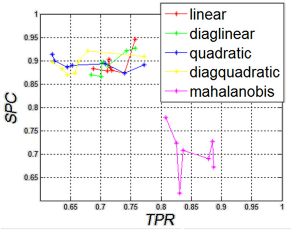
The results in Figure 2a) to g) show that regardless of the origin of the analyzed images of the thyroid (left, right lobe), and regardless of the section (transverse, longitudinal), the shape of the decision function formed between classes is not basic. The results of specificity (SPC) and sensitivity (TPR) for different types of classification are presented in Figure 3, which shows that Mahalanobis type slightly stands out. For all cases, the shapes of a decision function for classification are similar. It means that combining various sections, for example, LO with RO, LD with RD, etc., is justified and may increase the value of SPC and TPR. The values for the best classifier can be seen in Table 1 - specificity and Table 2- sensitivity.
Figure 3.
The graph of specificity ( SPC ) as a function of sensitivity ( TPR ) for different types of classification. As the graph shows, the results obtained for the linear diaglinear, quadratic and diagquadratic classifications are similar. Differences in sensitivity and specificity are clearly visible for the mahalanobis type. As shown later on, the calculated value of accuracy does not indicate clearly this type of classification as the best one.
Table 1.
Table showing the dependence of the results of specificity from the types of classification and the analyzed areas
| LO | RO | LRO | LD | RD | LRD | LROD | |
|---|---|---|---|---|---|---|---|
| linear |
0.883 |
0.873 |
0.878 |
0.945 |
0.879 |
0.902 |
0.885 |
| diaglinear |
0.866 |
0.888 |
0.869 |
0.927 |
0.896 |
0.920 |
0.894 |
| quadric |
0.900 |
0.873 |
0.886 |
0.890 |
0.913 |
0.893 |
0.889 |
| diagquadric |
0.883 |
0.873 |
0.869 |
0.909 |
0.896 |
0.920 |
0.898 |
| mahalanobis | 0.616 | 0.777 | 0.723 | 0.727 | 0.672 | 0.690 | 0.707 |
Table 2.
Table showing the dependence of the results of sensitivity from the types of classification and the analyzed areas
| LO | RO | LRO | LD | RD | LRD | LROD | |
|---|---|---|---|---|---|---|---|
| linear |
0.688 |
0.739 |
0.711 |
0.757 |
0.718 |
0.714 |
0.715 |
| diaglinear |
0.701 |
0.712 |
0.684 |
0.757 |
0.704 |
0.742 |
0.701 |
| quadric |
0.623 |
0.739 |
0.644 |
0.771 |
0.619 |
0.707 |
0.652 |
| diagquadric |
0.636 |
0.657 |
0.644 |
0.771 |
0.619 |
0.678 |
0.663 |
| mahalanobis | 0.831 | 0.808 | 0.825 | 0.885 | 0.887 | 0.878 | 0.836 |
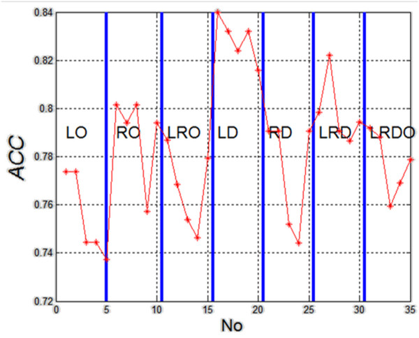
The results of specificity and sensitivity shown in Table 1 and Table 2 clearly indicate the linear method of classification of the left lobe in longitudinal section (LD). It can be also supported by making the calculation of accuracy (ACC= (TP + TN) / (TP + TN + FP + FN) ) for 35 cases (5 different types of classification and seven different configurations of the analyzed areas). The results are shown in Figure 4.
Figure 4.
The graph of accuracy (ACC) for subsequent analyzed cases (5 different types of classification and seven different configurations of the analyzed areas). The graph is divided into methods of measurement. For each measurement method, classification was carried out in succession with five methods: linear, diaglinear, quadric, diagquadric, mahalanobis. The graph shows clearly that the type of the ROI, and not the type of classification, significantly affects the results. In this case, these are the images of the right longitudinal section of the thyroid (LD).
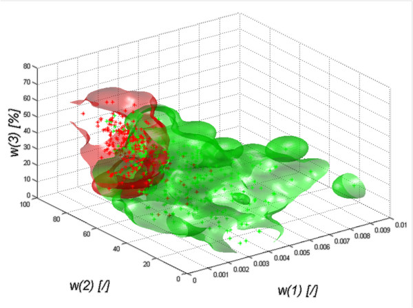
The presented results (Figure 4) unambiguously confirm the greatest diagnostic usefulness of ROI analysis of the left lobe in longitudinal section. The graph of classification objects (mahalanobis) depending on the features w(1), w(2) and w(3) is shown in Figure 5. Therefore, considerations of the impact of the method of marking the ROI, which will be presented later in the article, become interesting. ROI shifting and resizing indicated by an expert can influence greatly not only the features w(1), w(2) and w(3) but also specificity (SPC) and sensitivity (TPR), which will be presented in the following sections.
Figure 5.
The graph of classification objects (quadratic) of healthy subjects (red) from patients (green) depending on the features w(1), w(2) and w(3). The graph shows a visual distinction (classification) between healthy subjects and patients. The graph also shows a common area which is included in both data groups (those of patients and healthy subjects). The presented graph is one of the possibilities to create a closed area covering the cases of healthy subjects and patients in the axes of the three features w(1), w(2) and w(3).
Sensitivity to the change of parameters
The measured area (ROI), image Ls, underwent affine transformations in order to determine the dependence between the analyzed features w(1), w(2), w(3) and the size of the analyzed area as well as its position and rotation. The sensitivity analysis of these changes will be considered in subsequent sections.
This analysis was considered in two aspects:
- sensitivity of features w(1), w(2) and w(3) to affine transformations of the ROI,
- sensitivity of classification results to affine transformations of the ROI.
The analysis of changes in the value of w(1), w(2) and w(3) is important in this case because it points to their direct link with affine transformations (rotation, resizing and repositioning of the ROI). A direct comparison enables to assess the correctness of the formulation of features and their sensitivity to, for example, image rotation. This, in turn, enables to indicate which feature (and to what extent) depends on the position of the ultrasound head. It is also a condition to modify the formulation of a given feature so that it is only slightly dependent on the rotation.
Regardless of these results, the quality of the classification results for affine transformations -derived on the basis of all the features w(1), w(2) and w(3) – was assessed. The results demonstrate sensitivity of the algorithm which is considered as a measurement (diagnostic) method.
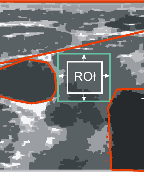
Sensitivity assessment of the algorithm will be carried out for the changes in the position, size and rotation of the ROI. A range of changes in these parameters is limited by (Figure 6):
Figure 6.
The schematic diagram of the thyroid ultrasound image showing a typical distribution of the ROI (white) marked by a specialist physician and the distribution of adjacent organs (red). Acceptable ranges of variation in the ROI shift, size and rotation are highlighted in green. On this basis, and analyzing all the images, restrictions on ranges of variation in the ROI position and size were specified.
- organs immediately adjacent to the thyroid lobe,
- image borders - moved or enlarged ROI may not exceed the limits of the image,
- ROI cannot be smaller than 10×10 pixels - this limitation is recognized in the definition of the coefficients w(1), w(2) and w(3).
Therefore, rounded values of the changes in the ROI position in the range of ±20 pixels of the ROI and its size of 10×10 to 90×90 were adopted. These values do not result in a breach of any of the above restrictions on the ROI for any of the analyzed images.
The only correct position and size of the ROI are determined by a specialist physician. Results and their impact on the value of accuracy will be observed (calculated) during ROI shifting, resizing or rotating.
The algorithm sensitivity to the resize of the marked area
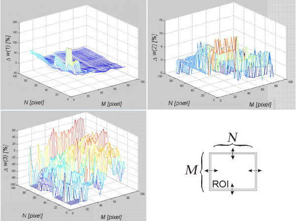
The measurement of the algorithm sensitivity to the change of size, resolution of the image Ls and, thus, the selected area was carried out on a healthy subject’s left thyroid lobe in transverse section (LD). For all the analyzed cases, the size of Ls images ranged from 24 to 81 rows and 20 to 92 columns. On this basis and considering specificity of obtaining the feature w(3) (the number of instances of the areas of size 8×8), the range of variation of the ROI was set. The selected area Ls was modified by changing its size from M×N=10×10 pixels to 90×90 pixels whereas the size of a properly selected area was 50×50 pixels. The change of size concerned independently modification of the number of rows and columns by 1 pixel. The minimum value of the ROI (10×10) resulted from the limitations of the algorithm operation in the case of the feature w(3). The maximum value (90×90) was limited by the edge of the image for the utmost part of the area. A USG specialist marked the area of 50×50 pixels which is the base size. For each modified area, the percentage changes (appropriate error as a percentage) of the features w(1), w(2), w(3) were measured. The graphs (Figure 7) show the obtained results.
Figure 7.
Assessment of the algorithm sensitivity, w(1), w(2) and w(3) to the change of the number of rows and columns of the analyzed are in the range from M×N=10×10 to 90×90. The graphs show the changes in individual features in response to changes in the size of the selected ROI. The graphs indicate that the features w(1) and w(2) are very sensitive to the size of the ROI. The smaller the ROI is, the bigger the measurement error of the values w(1) and w(2) gets. The feature w(3) is less dependent on the size of the ROI.
The graphs (Figure 7) indicate that the feature w(3) is most sensitive to the change in the size of Ls. A small change in the number of rows and columns of the covered range indicated by the doctor influences considerably the value of the feature w(3). These changes concern tens of percent for the decrease or increase of the area by a few pixels. Changes to the feature w(1) are much milder and amount to several percent. When the area Ls increases, the value of the feature w(1) slightly changes. Only a significant reduction in the area Ls increases the error for the measurement of the feature w(1) up to 100%. Sensitivity of the feature w(3) to a change of the size of the area Ls looks completely different. The value of the feature varies by only a few percent in the full measured range. Discrete changes, visible on the graph, are due to the definition of the feature w(3) which is based on a histogram. Changes in the value of w(3) result from a change in the shape of the histogram. Therefore, the number of pixels of a given brightness and its proportion in relation to different brightness have to change. For the image Ls, it means that the texture changes. For this reason, changes in the size of the area Ls only slightly affect changes in the value of w(3).
The algorithm sensitivity to the change of the marked area position
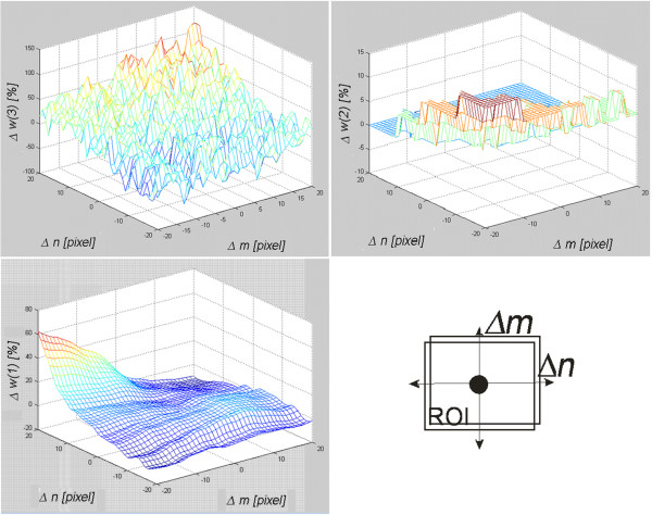
The measurement of the algorithm sensitivity to the change of the Ls position in the thyroid ultrasound image was carried out by pushing the area marked by the expert in the range of ±20 pixels in the axes of rows (m) and columns (n). The range of ±20 pixels resulted from the variability in the content of the image for which the shift of more than 20 pixels resulted in an analysis of a neighboring organ. The ultrasound image was from a healthy subject and it was a transverse section of the thyroid left lobe. The results for the measured features w(1), w(2) and w(3) are shown in Figure 8.
Figure 8.
Assessment of the algorithm sensitivity, w(1), w(2) and w(3) to the change of the analyzed area position in the range of ±20 pixels in rows (m) and columns (n). The graphs indicate that the shift of the ROI in the range of −20 pixels in both axes increases the value of the feature w(2) by about 10%. For the same shift, the values of the feature w(1) and w(3) do not change. The feature w(3) increases its error to the value of 60% but only for the shift of -20 pixels in one axis and +20 pixels in the other.
It can be observed that values of the features w(1), w(2) and w(3) behave differently when the position of the Ls in the axes of rows and columns is changed. For the extreme positions, i.e. Δm=20, Δn=20 of the feature w(1), Δm=−20, Δn=−20 of the feature w(2) and Δm=−20, Δn=20 of the feature w(3), maximum values are achievable. Thus, a significant shift (more than 20 pixels) of the area Ls affects the results to a considerable extent. Globally, the feature w(3) is least sensitive to shifts of the area Ls.
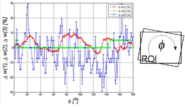
The algorithm sensitivity to rotation around its own axis
Sensitivity to rotation of the analyzed area Ls is the last measured sensitivity to the change of parameters (of the features w(1), w(2) and w(3)). The analyzed area was rotated around an axis situated in the center of the area Ls in the angular range ϕ=0 to 180o by every 1o using a bilinear interpolation method. As in the previous measurements, the analyzed area concerned the thyroid texture in a healthy patient’s ultrasound image in the left transverse section. The results are shown in Figure 9.
Figure 9.
Assessment of the algorithm sensitivity, w(1), w(2) and w(3), to the rotation of the analyzed area in the angular range ofϕ=0 to 180oby every 1o. The rotation of the ROI affects the features w(1) and w(3) to the greatest extent. The change in the value of the error of the feature w(1) is cyclic and its frequency of changes is several times larger than the rotation.
The graph in Figure 9 shows that sensitivity to the rotation of the analyzed area is the highest for the feature w(3). The value of the feature w(2) changes slightly whereas the value of the feature w(1) changes oscillating. These oscillations result from the modification (due to rotation) of the Ls image content into new areas which contribute significantly to the value of STD and, therefore, to the value of the feature w(1).
In summary, the presented algorithm is least sensitive to the rotation of the area Ls and the feature w(2) is least sensitive to affine transformations (rotation, repositioning and resizing).
Assessment of the classification method sensitivity to affine transformations of the ROI
Assessment of sensitivity presented in the previous sections is determined on the basis of the results obtained from the individual features w(1), w(2) and w(3). These results are meaningful when the features are considered separately. However, in the case of the presented algorithm for classification, they form a coherent whole equally influencing the decision function. Therefore, it becomes legitimate to analyze sensitivity of the classification method to the presented affine transformations – ROI shifting and resizing (Ls). Ls image rotation will not be analyzed because, as it has been proved in previous sections, its influence on the results is negligibly small.
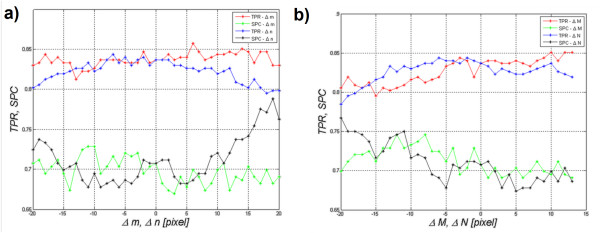
The figure below (Figure 10a)) shows the impact of a shift in the area Ls in the range of ±20 pixels in the axes of rows or columns on the values of SPC and TPR (Δm=±20 or Δn=±20). Figure 10b), on the other hand, shows the impact of changes in the size of the ROI on the obtained results (SPC and TPR). Since the ROI sizes are different for different ultrasound images, values of the changes M×N are given as differences with respect to the original size in the range of ±20 pixels, i.e.: Δm=±20 or Δn=±20. Reducing the area did not result, in any case, in the ROI smaller than 5×5 pixels. Moreover, at a magnification, the ROI did not exceed the limits of an ultrasound image.
Figure 10.
Assessment of the algorithm sensitivity (specificity (SPC), sensitivity (TPR)) to changes in: a) ROI position in the axes of rows and columns (Δm, Δn) in the range of ±20 pixels and b) ROI size in the axes of rows and columns (ΔM, ΔN) in the range of ±20 pixels. The presented graph a) suggests many conclusions concerning the impact of the change in the position of the ROI on sensitivity and specificity. For example, the ROI shift in the range of ±10 pixels in the row or column axis slightly affects the values of specificity and sensitivity (changes at below 0.05). The figure b) shows that an increase in the size of the ROI by 13 pixels in rows or by 7, 8 pixels in rows and columns causes a significant increase in specificity and sensitivity by approximately 0.03. The analysis of this graph a) and the graph b) indicates that the areas were properly marked by an expert. In another case, the maximum values of sensitivity and specificity for the shift 0 and the change of size 0 of the marked ROI were not visible.
The graph in Figure 10a) shows that changes in ROI position in the range of ±20 pixels affect specificity and sensitivity to a lesser extent. When analyzing both Figure 10a) and b), some interesting properties and characteristics of the measurements can be noticed:
-ROI shift in the range of ±10 pixels in the row or column axis slightly affects the results of specificity and sensitivity (changes of less than 0.05),
-for a shift to the left or to the top by 10 pixels, SPC increases by approximately 0.03,
-an increase in the size of the ROI by 13 pixels in rows or by 7 to 8 pixels in rows and columns causes a significant increase in specificity and sensitivity by approximately 0.03.
In conclusion, the choice of the area conducted by the expert and the algorithm are very good. ROI shifts in the range of ±10 pixels in the row or column axis as well as a decrease or increase in the ROI do not significantly affect the results. Therefore, the algorithm is resistant to fluctuations of the ROI (of both position and size) and its rotation (as demonstrated in the previous section).
Comparison with other results
In the literature described in the introduction [1-39], authors present several original methods of ultrasound image analysis. These methods are very interesting from the point of view of an ultrasound operator as they increase the accuracy and efficiency of diagnosis. Verification of sensitivity of the presented algorithms to changes in parametres, such as position, size and rotation of the ROI, is also an important feature for operators. This sensitivity analysis is important from the point of view of medical practice and interindividual variation. These elements may significantly influence the obtained results which testify to the quality of the algorithm. It may be that the advantage of one approach over the other forces highly accurate and precise indication of the ROI.
Comparing the described algorithm with other algorithms, a few common features may be found:
-the histogram analysis of our algorithm fulfills a similar function as a classical analysis of the histogram described in paper [10]. However, in that paper only one feature is taken into account, namely w(2) which is the minimum brightness, but after the removal of noise. Noise is defined as pixels whose sum is less than 20% of the calculated maximum amount of pixels.
-the analysis of the features of our algorithm is similar to the analysis of another set of features (entropy, sum variance and mean value) presented in paper [22]. Accuracy obtained there reaches 93.6%. However, the example given does not apply to Hashimoto’s disease.
-comparison of methods of Co-occurrence matrix with the Radon transform and Muzzolini’s spatial features is shown in paper [19]. However, the results shown do not relate directly to Hashimoto’s disease and do not analyze the impact of changes in the position of ROI on the obtained results.
-simple analysis of the areas associated with Hashimoto’s disease is shown in paper [42]. The results were obtained depending on the analysis method; sensitivity in the range of 71% to 88% and specificity in the range of 67% to 91%. These results are comparable with the results obtained with our algorithm, i.e. sensitivity 76% and specificity 95%. It should be noted that in the quoted paper [42], ROI areas were carefully selected by experts and some of the artifacts were manually eliminated.
In addition, the results of sensitivity, specificity and accuracy obtained from this discriminant analysis were compared in detail with other known methods [10,12,39]. Calculations were performed for the same group of 73 patients with Hashimoto’s disease and 59 healthy subjects. The images concerned only the left thyroid lobe in cross section (LD).
The following results were obtained:
Method 1: a classification method based on thresholding of mean values of brightness levels [10]– sensitivity 92% and specificity 40%. ACC=76%,
Method 2: a method that uses decision trees described in paper [39] - sensitivity 88% and specificity 76% ACC=84% for a pruned decision tree,
Method 3: a discriminatory classification method proposed in this paper - sensitivity 76% and specificity 95%. ACC=84%.
The exact differences between the three methods are described in detail below.
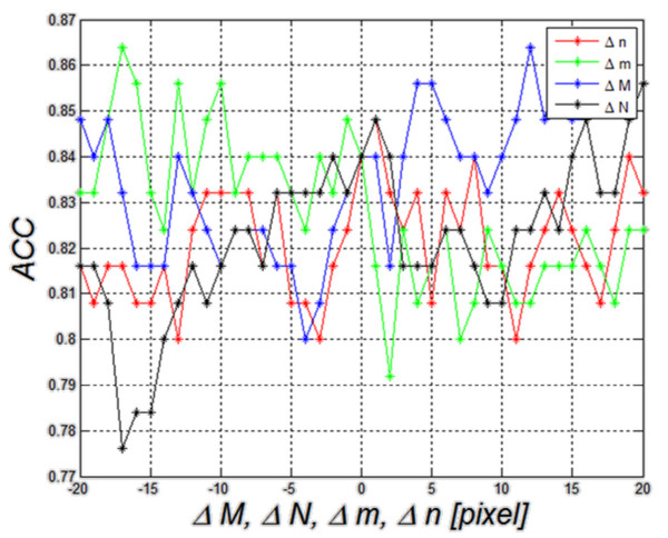
Method 3. The last results of changes in accuracy as a function of Δm are shown in Figure 13 and they concern the third method described in this paper. Changes Δm, Δn, ΔM, ΔN within the same limits (±20 pixels) affect the result of accuracy by approximately ±5%. The resulting range of accuracy variation (5%) is the smallest of all the compared methods.
Figure 13.
Graph of changes in ACC as a function of Δm, Δn, ΔM and ΔN for linear dyscryminat analisys– this is the third described method (method 3). The graph shows that the value of ACC is 84% for Δm=Δn=ΔM=ΔN=0. The other values of ACC change in the range of about 5% for ROI shifts and size changes. The direction of these changes is different and it is difficult to clearly link it to ROI shift and resize.
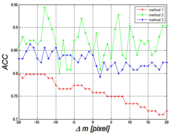
In order to better compare the three methods (method 1, 2 and 3), they are shown jointly in Figure 14. The worst results of ACC (ACC=76%) are obtained for the method of thresholding (method 1) of echogenicity average levels (Figure 14). Changes in ACC for changes Δm=±20 pixels range from 71% to 80%. When decision trees are used as a classifier (method 2), ACC variation range comprised between 80% and 95%. It was the best possible result obtained for the changes Δm. For Δm=0, it was 84%. Much smaller changes in ACC for fluctuations of Δm can be observed in the discriminant method (method 3). For this method, changes in ACC are much smaller in the full range of Δm variation and they range from 79% to 87% of ACC. For Δm=0, ACC is 84%. Discriminant analysis is characterized by minor changes in accuracy for different positions of the ROI as compared to the method 2 that uses decision trees.
Figure 14.
Graph of changes in ACC as a function of Δm for the three compared methods: method 1- thresholding, method 2- decision trees and method 3- discriminant analysis. The worst results of classification of patients with Hashimoto’s disease (ACC=77%) were obtained for the method of thresholding of echogenicity average levels (red). Comparable results for Δm=0 were obtained for decision trees and discriminant analysis. Here discriminant analysis is characterized by smaller changes in accuracy for different positions of the ROI.
Therefore, in the assessment of Hashimoto’s disease, more than one feature needs to be taken into account. Moreover, DICOM files should be analyzed directly and one of the two of the compared classifiers should be used (discriminant analysis or decision trees- method 3 and 2). Not only the absolute values of ACC but also the dynamics of their changes for small ROI displacements should be taken into account when analyzing the changes in results caused by ROI displacements.
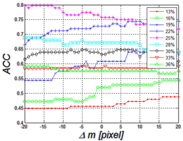
Method 1. The first method is based on thresholding of echogenicity mean value (described in detail in [10] ). When applied to these data, it enables to obtain a result of ACC equal to 76% for the gray level threshold set to 25% of luminance (Figure 11). The range of average gray levels in the ROI for the analyzed cases was between 10% and 39% of saturation. Therefore, the graph shown in Figure 11 was carried out for different values of the threshold changed in the range of 13% to 36% in increments of 2.9% (assuming a step which is the tenth part of the range of 39%-10%). It can be observed that for the threshold value of 25%, shift of the ROI in the range of ±20 pixels affects significantly the value of accuracy– ACC changes by 7%. For the other threshold settings, the value of changes of Δm remains at a similar level, not exceeding 10%. In no sequence, a maximum for the value of Δm=0 is visible. Changes in the accuracy for different Δm do not have a well-defined direction of growth. Thus, it can be ultimately assumed that in the method of thresholding of echogenicity average level, ROI repositioning affects the result of accuracy to the extent of less than 10%.
Figure 11.
Graph of changes in theACCvalue as a function of Δmfor five different threshold settings for the first compared method (method 1). These results are related to the impact of ROI repositioning on the value of ACC. Threshold values are mean values of echogenicity in the ROI. The best results were obtained with a threshold of 25%. For this value, changes in ACC are less than 10%.
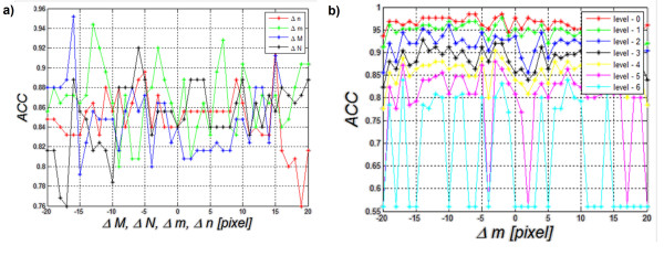
Method 2: Another method uses decision trees (described in detail in [39] ). When applied to the collected data, it enables to obtain accuracy at 84%. In this case, accuracy variation was evaluated as a function of changes in ROI size and shift (Δm, Δn, ΔM, ΔN). The results for the pruned decision tree are shown in Figure 12a). The best tree is the one that has a residual variance that is no more than one standard error above the minimum value along the cross-validation line. Figure 12a) shows that changes in accuracy for changes in the values Δm, Δn, ΔM and ΔN are similar to the ones observed for echogenicity thresholding method and change by about 10%. The results also show a range of changes in the value of accuracy for each shift or resize of the ROI. The greater changes in the size or shift of the ROI are, the higher accuracy rate of change becomes. For example, for ΔM revised from the value of −16 to −15 pixels, the change in ACC reaches 16% (95%-79%). For ΔM as well as Δm, Δn and ΔN close to zero, ACC changes are smaller and reach the values of 5, 10%.
Figure 12.
Graph of changes inACCas a function of Δm, Δn, ΔMand ΔNwhen decision trees are used as a classifier a) and graph of changes inACCas a function of Δmfor each level of the decision tree cutting b)- this is the second compared method (method 2). Changes (graph a) in the position and size of the ROI affect to an increasing extent the dynamics of changes in ACC. For the basic setting Δm=Δn=ΔM=ΔN=0, ACC is equal to 84%. The further from the basic setting 0 pixels, the higher the dynamics of changes in ACC becomes. The value of the level 0 (graph b) means no tree pruning. Trees are pruned based on an optimal pruning scheme that first pruned branches give less improvement in error cost. For most of the created decision trees, changes in ACC are in the range of 5%. When decision trees are cut too much, they lose their ability of correct classification. Such a situation is visible in the chart below (level 6) where ACC changes from 85% to 55%.
Narrowing the analysis to observation of accuracy changes only as a function of Δm, the impact of pruning the decision tree on the results is shown in Figure 12b). The degree of cutting the decision tree is dependent on the level ranging from 0 to 6 where level = 0 means no tree pruning. Trees are pruned based on an optimal pruning scheme that first pruned branches give less improvement in error cost. It can be seen that accuracy values vary depending on the degree of cutting the decision tree. Δm changes affect the value of accuracy by 5% for the first level values. When the decision tree is pruned too much, it loses its ability of classification and the error of accuracy reaches 30%.
Summary
This paper presents the influence of a measurement method of echogenicity in the diagnosis of Hashimoto’s disease, with a particular reference to the assessment of the algorithm sensitivity to a change in the ROI position. Classification was performed using a discriminant analysis for the following five options: linear, diaglinear, quadratic, diagquadratic and mahalanobis. Transverse and longitudinal sections of the thyroid right and left sides were analyzed. The analysis showed that the highest accuracy was obtained for the longitudinal section (LD) with the linear method, obtaining sensitivity = 76%, specificity = 95% and ACC = 84%. The impact of changes in the location of the ROI on the results was shown in one example and, separately, for all the analyzed cases. A change in the ROI position has the greatest impact on the value of features w(1) and w(3). The feature w(3) showed the greatest dependence on both the ROI position and also change of its size in the measured range of ±20 pixels. The percentage changes in the feature w(3) in the measured range Δm=±20 pixels and Δn =±20 pixels exceed 100%, while the changes of the feature w(2) amount to 5, 10%. The change in the value of w(1) is between 50% and 60%. The analysis of the results (mainly in Figure 9), confirms low dependence (below 30%) of any feature w(1), w(2) or w(3) on the ROI rotation in the range of 0 to 180o. A significant variation in the features w(3), w(2) or w(1) is not meaningful in relation to changes in sensitivity and specificity for the analyzed group of patients. Sensitivity assessment studies confirm that changes in the ROI position and size have little effect on sensitivity and specificity. SPC changes from 60% to 74% and TPR from 75% to 83% in the analysis of all cases of RLOD. Comparing the obtained results with other methods (method 1,2) known from the literature is also interesting. In the case of the classification method which uses decision trees [39] - method 2, the dynamics of ACC changes was at 15% (from 80% to 95%) for the full ROI displacement by Δm=±20. In the case of the method of thresholding (method 1) of echogenicity average levels, ACC was 76% for Δm=0 and the variation range of ACC was from 71% to 80% for Δm=±20 pixels.
Competing interests
The authors declare that they have no competing interests.
Authors’ contributions
RK and AK suggested the algorithm for analysing and processing images, implemented it and analysed the ultrasound images. JM conducted the study, participated in the collection of literature and supervised the base at the time of collecting material. AW also conducted the study and prepared material for analysis. WZ came up with the concept of image analysis in Hashimoto’s disease, collected and analyzed literature, conducted studies, correlated the images with the results and participated in the analysis. ZW and WW coordinated the work of the whole team and consulted all the stages of the project. All authors have read and approved the final manuscript.
Contributor Information
Robert Koprowski, Email: robert.koprowski@us.edu.pl.
Anna Korzyńska, Email: anna.korzynska@ibib.waw.pl.
Zygmunt Wróbel, Email: zygmunt.wrobel@us.edu.pl.
Witold Zieleźnik, Email: witold.zieleznik@gmail.com.
Agnieszka Witkowska, Email: witkowskaaga@op.pl.
Justyna Małyszek, Email: jmalyszek@gmail.com.
Waldemar Wójcik, Email: waldemar.wojcik@pollub.pl.
Acknowledgements
The study carried out under KBN N518 047 32/3670 grant “Automatic analysis of a thyroid image as a tool used to make changes in the thyroid more objective”.
References
- Marwaha RK, Tandon N, Kanwar R, Ganie MA, Bhattacharya V, Reddy DH, Gopalakrishnan S, Aggarwal R, Grewal K, Ganguly SK, Mani K. Evaluation of the role of ultrasonography in diagnosis of autoimmune thyroiditis in goitrous children. Indian Pediatric. 2008;45(4):279–284. [PubMed] [Google Scholar]
- Marcocci C, Vitti P, Cetani F, Catalano F, Concetti R, Pinchera A. Thyroid ultrasonography helps to identify patients with diffuse lymphocytic thyroiditis who are prone to develop hypothyroidism. Clin Endocrinol Metab. 1991;72:209–213. doi: 10.1210/jcem-72-1-209. [DOI] [PubMed] [Google Scholar]
- Hayashi N, Tamaki N. Sonography of Hashimoto’s thyroiditis. J Clin Ultrasound. 1986;14:123–126. doi: 10.1002/jcu.1870140208. [DOI] [PubMed] [Google Scholar]
- Gutekunst R, Hafermann W, Mansky T, Scriba PC. Ultrasonography related to clinical and laboratory findings in lymphocytic thyroiditis. Acta Endocrinol. 1989;121:129–135. doi: 10.1530/acta.0.1210129. [DOI] [PubMed] [Google Scholar]
- Raber W, Gessl A, Nowotny P, Vierhapper H. Thyroid ultrasound versus antithyroid peroxidase antibody determination: a cohort study of four hundred fifty-one subjects. Thyroid. 2002;12(8):725–731. doi: 10.1089/105072502760258712. [DOI] [PubMed] [Google Scholar]
- Loy M, Cianchetti ME, Cardia F, Melis A, Boi F, Mariotti S. Correlation of computerized gray-scale sonographic findings with thyroid function and thyroid autoimmune activity in patients with Hashimoto’s thyroiditis. J Clin Ultrasound. 2004;32(3):136–140. doi: 10.1002/jcu.20008. [DOI] [PubMed] [Google Scholar]
- Mailloux G, Bertrand M, Stampfler R, Ethier S. Computer analysis of echographic textures in Hashimoto disease of the thyroid. J Clin Ultrasound. 1986;14(7):521–527. doi: 10.1002/jcu.1870140705. [DOI] [PubMed] [Google Scholar]
- Baldini M, Orsatti A, Bonfanti MT, Castagnone D, Cantalamessa L. Relationship between the Sonographic Appearance of the Thyroid and the Clinical Course and Autoimmune Activity of Graves’ Disease. J Clin Ultrasound. 2005;33(8):381–385. doi: 10.1002/jcu.20157. [DOI] [PubMed] [Google Scholar]
- Schiemann U, Gellner R, Riemann B, Schierbaum G, Menzel J, Domschke W, Hengst K. Standardized grey scale ultrasonography in Graves’ disease: correlation toautoimmune activity. Eur J Endocrinol. 1999;141(4):332–336. doi: 10.1530/eje.0.1410332. [DOI] [PubMed] [Google Scholar]
- Mazzotii G, Sorvillo F, Iorio S, Carbone A, Romeo A, Piscopo M, Capuano S, Capuano E, Amato G, Carella C. Grey-scale analysis allows a quantitative evaluation of thyroid echogenicity in the patients with Hashimoto’s thyroiditis. Clin Endocrinol. 2003;59:223–229. doi: 10.1046/j.1365-2265.2003.01829.x. [DOI] [PubMed] [Google Scholar]
- Uwe S, Avenhaus W, Konturek J, Gellner R, Hengst K, Gross M. Relationship of clinical features and laboratory parameters to thyroid echogenicity measured by standardized grey scale ultrasonography in patients with Hashimoto’s thyroiditis. Med Sci Monit. 2003;9(4):49–53. [PubMed] [Google Scholar]
- Mailloux G, Bertrand M, Stampfler R, Ethier S. Computer analysis of echographic textures in Hashimoto disease of the thyroid. JCU J Clin Ultrasound. 1986;14(7):521–527. doi: 10.1002/jcu.1870140705. [DOI] [PubMed] [Google Scholar]
- Mailloux GE, Bertrand M, Stampfler R, Ethier S. Texture analysis of ultrasound B-mode images by segmentation. Ultrason Imaging. 1984;6(3):262–277. doi: 10.1016/0161-7346(84)90012-9. [DOI] [PubMed] [Google Scholar]
- Mailloux GE, Bertrand M, Stampfler R, Ethier S. Local histogram information content of ultrasound B-mode echographic texture. Ultrasound Med Biol. 1985;11(5):743–750. doi: 10.1016/0301-5629(85)90108-5. [DOI] [PubMed] [Google Scholar]
- Smutek D, Sara R, Sucharda P, Tjahjadi T, Svec M. Image texture analysis of sonograms in chronic inflammations of thyroid gland. Ultrasound Med Biol. 2003;29(11):1531–1543. doi: 10.1016/S0301-5629(03)01049-4. [DOI] [PubMed] [Google Scholar]
- Bastanfard M, Jalaeian B, Jafari S. Analysis of Sonogram Images of Thyroid Gland, Based on Wavelet Transform. World Academy of Science, Engineering and Technology; 2007. pp. 27–39. [Google Scholar]
- Savelonas MA, Iakovidis DK, Dimitropoulos N, Maroulis D. Computational Characterization of Thyroid Tissue in the Radon Domain. IEEE Int Symp Comput-Based Med Syst. 2007;33:189–192. [Google Scholar]
- Dimitris KI, Eystratios GK, Maroulis D. Fuzzy Local Binary Patterns for Ultrasound Texture Characterization. Image Anal and Recognit Lecture Notes in Computer Sci. 2008;5112:750–759. doi: 10.1007/978-3-540-69812-8_74. [DOI] [Google Scholar]
- Dimitris KI, Eystratios GK, Dimitris M. Fusion of fuzzy statistical distributions for classification of thyroid ultrasound patterns. Artif Intell Med. 2010;50(1):33–41. doi: 10.1016/j.artmed.2010.04.004. [DOI] [PubMed] [Google Scholar]
- Keramidas EG, Maroulis D, Iakovidis DK. A Thyroid Nodule Detection System for Analysis of Ultrasound Images and Videos. Springer Science+Business Media, J Med Syst. 2012;36(3):1271–1281. doi: 10.1007/s10916-010-9588-7. [DOI] [PubMed] [Google Scholar]
- Kotropoulos C, Pitas I. Segmentation of ultrasonic images using Support Vector Machines. Pattern Recognit Lett. 2003;24(4–5):715–727. [Google Scholar]
- Tsantis S, Glotsos D, Spyridonos P, Kalatzis G, Dimitropoulos N, Nikiforidis G, Cavouras D. Improving diagnostic accuracy in the classification of thyroid cancer by combining quantitative information extracted from both ultrasound and cytological images, 1st International Conference “From Scientific Computing to Computational Engineering” 1st IC-SCCE 8–10. © IC-SCCE, Athens; 2004. pp. 087–088. [Google Scholar]
- Šára R, Smutek D, Sucharda P, Svacina S. Systematic construction of texture features for Hashimoto’s lymphocytic thyroiditis recognition from sonographic images. AIME. 2001;2101:339–348. [Google Scholar]
- Tesa L, Smutek D. Ultrasonography diagnostics using gaussian mixture model. Jozef Stefan Institute, Izola, Slovenia; 2005. (6th International PhD Workshop on Systems and Control). [Google Scholar]
- Sujana H, Swarnamani S, Suresh S. Application of artificial neural networks for the classification of liver lesions by image texture parameters. Ultrasound Med Biol. 1996;22(9):1177–1181. doi: 10.1016/S0301-5629(96)00144-5. [DOI] [PubMed] [Google Scholar]
- Cavouras D. et al. Computer image analysis of ultrasound images for discriminating and grading liver parenchyma disease employing a hierarchical decision tree scheme and the multilayer perceptron neural network classifier. In Med Inform Eur. 1997;2:522–526. [PubMed] [Google Scholar]
- Bidi ABH. Image texture analysis of transvaginal ultrasound in monitoring ovarian cancer. Cardiff School of Engineering, Cardiff University; 2011. (A thesis submitted to the Cardiff University in candidature for the degree of Doctor of Philosophy, Institute of Medical Engineering and Medical Physics). [Google Scholar]
- Chan K. Adaptation of ultrasound image texture characterization parameters. In Proc of the 20th Ann Int Conf of the IEEE Eng in Med and Biol Soc. 1998;2:804–807. [Google Scholar]
- Keramidas EG, Iakovidis D, Maroulis D, Karkanis SA. Efficient and effective ultrasound image analysis scheme for thyroid nodule detection. Lect Notes Comput Sci. 2007;4633:1052–1060. doi: 10.1007/978-3-540-74260-9_93. [DOI] [Google Scholar]
- Hirning T. et al. Quantification and classification of echographic findings in the thyroid gland by computerized B-mode texture analysis. Eur J Radiol. 1989;9(4):244–247. [PubMed] [Google Scholar]
- Svec M, Sara R, Smutek D. Sensitivity Analysis for Reproducibility of Ultrasound Image Classification. Czech Technical University; 2003. (Research Report CTU–CMP–2003–22, Center for Machine Perception). [Google Scholar]
- Gul K, Dirikoc A, Kiyak G, Ersoy PE, Ugras NS, Ersoy R, Cakir B. The Association Between Thyroid Carcinoma and Hashimoto’s Thyroiditis, The Ultrasonographic and Histopathologic Characteristics of Malignant Nodules. Thyroid. 2010;20(8):873–878. doi: 10.1089/thy.2009.0118. [DOI] [PubMed] [Google Scholar]
- Korzyńska A, Hoppe A, Strojny W, Wertheim D. Investigation of a combined texture and contour method for segmentation of light microscopy cell images. Proceedings of The Second IASTED International Conference on, Biomedical Engineering; 2004. pp. 234–239. [Google Scholar]
- Toufik EA. Automatic classification of the thyroid gland diseases by a histogram. Czech Technical University, Prague, Czech Republic; 2001. (Master’s thesis, Faculty of Electrical Engineering). [Google Scholar]
- Zieleźnik W, Witkowska A, Małyszek-Tumidajewicz J, Koprowski R, Stępień B, Owczarek A, Koprowski R, Wójcik W. The new method of analysis thyroid echogenicity in the patients with Hashimoto’s disease. sent to Thyroid. 2012.
- Zieleźnik W, Małyszek‐Tumidajewicz J, Stęchły T, Stępień B, Wójcik W, Owczarek. The analysis of thyroid ultrasound echogenicity in the patients with hashimoto’s disease. Eur Thyroid J. 2011;5:160. [Google Scholar]
- Koprowski R, Wróbel Z, Zieleźnik W. Automatic ultrasound image analysis in Hashimoto’s disease. Lect Notes in Comput Sci - Adv in Pattern Recognit. 2010;6256:98–106. doi: 10.1007/978-3-642-15992-3_11. [DOI] [Google Scholar]
- Koprowski R, Wróbel Z, Zieleźnik W. Analysis of thyroid ultrasonogram in Hashimoto’s disease, The 2010 International Congress on Computer Applications and Computational Science. IRAST, Singapore; 2010. pp. 448–451. [Google Scholar]
- Koprowski R, Wróbel Z, Zieleźnik W, Małyszek J, Witkowska A, Wójcik W. Relevance of features derived from ultrasound images of the thyroid in the diagnosis of Hashimoto’s disease. Biomed Eng Online. 2012;11:48. doi: 10.1186/1475-925X-11-48. [DOI] [PMC free article] [PubMed] [Google Scholar]
- Gonzalez RC, Woods RE. Digital Image Processing Using Matlab. Printed in United States of America, Prentice Hall; 2008. [Google Scholar]
- McLachlan GJ. Discriminant Analysis and Statistical Pattern Recognition. Wiley; 2004. [Google Scholar]
- Banaka I, Kaltsas G, Antoniou S, Kanakis G, Zilos A, Baltas CS, Thomas D. Prognostic value of vascularity index for the diagnosis of autoimmune thyroid disease. JBR–BTR. 2011;94:185–190. doi: 10.5334/jbr-btr.582. [DOI] [PubMed] [Google Scholar]


