Abstract
Objective:
Despite new developments in the management of osteoporotic fractures, complications like screw cutout are still found in the fixation of proximal femur fractures even with biomechanically proven better implants like proximal femoral nail antirotation (PFNA). The purpose of this cadaveric study was to investigate the biomechanical stability of this device in relation to two common positions (center-center and inferior-center) of the helical blade in the femoral head in unstable trochanteric fractures.
Materials and Methods:
Eight pairs of human cadaveric femurs were used; in one group [center-center (C-C) group], the helical blade of PFNA was fixed randomly in central position both in anteroposterior and lateral view, whereas in the other group it was fixed in inferior one-third position in anteroposterior and in central position in lateral view [inferior-center (I-C) group]. Unstable intertrochanteric fracture was created and each specimen was loaded cyclically till load to failure
Results:
Angular and rotational displacements were significantly higher within the C-C group compared to the I-C group in both unloaded and loaded condition. Loading to failure was higher in the I-C group compared to the C-C group. No statistical significance was found for this parameter. Correlations between tip apex distance, cyclic loading which lead to femoral head displacement, and ultimate load to failure showed a significant positive relationship.
Conclusion:
The I-C group was superior to the C-C group and provided better biomechanical stability for angular and rotational displacement. This study would be a stimulus for further experimental studies with larger number specimens and complex loading protocols at multicentres.
Keywords: Biomechanical study, cadaveric study, unstable trochanteric fracture, helical blade position, PFNA
INTRODUCTION
Unstable intertrochanteric femoral fractures are common in the elderly, and the incidence of these fractures is continuously increasing worldwide.1 Biomechanically, intramedullary devices are superior to traditional extramedullary devices for these fractures. Among the intramedullary devices, proximal femur nailing antirotation (PFNA) (Synthes Inc., Bettlach, Switzerland) is one of the devices in the treatment of unstable intertrochanteric femoral fractures.2 This device combines the biomechanically favorable characteristics of an intramedullary nail with a minimally invasive surgical technique.3 This device has helical-shaped blade which have been biomechanically proven to have significantly higher cutout resistance in these fractures.4 Despite new developments in the management of age-related osteoporotic fractures, serious clinical complications such as screw cut out are still found in the fixation of proximal femur fractures. Cutout rate of the PFNA of up to 3.6% is documented in the literature.5 Apart from patient-dependent factors like osteoporosis, surgeon dependent factors like suboptimal positioning of the device plays a major role in the failure of fixation.1,6–8
The cutout of the lag screw is related to various factors; however, there is general agreement that cutout failure is mainly due to malpositioning of the lag screw in the femoral head.8–10 There is no single opinion regarding optimal position of the lag screw in the femoral head. Center-center,11–13 posterior-inferior,14,15 or inferior-center16–18 placement of the lag screw was recommended by different studies. Moreover, there are no studies so far which evaluated the performance of the newer device PFNA in relation to different positions of the helical blade in the femoral head.
The aim of our study was to investigate the biomechanical stability of this device in relation to center-center versus the inferior-center position of the helical blade in the cadaveric femoral head in unstable trochanteric femoral fractures. We hypothesized there is no significant difference between the two blade positions with respect to angular (varus) and rotational displacement after cyclic loading and ultimate load to failure.
MATERIALS AND METHODS
Specimens
Eight paired (n = 16 femurs) fresh frozen human cadaver femora were harvested after obtaining consent from the local ethics committee. The mean age, weight, and height were 74 ± 4.8 years (68–87 years), 61.3 ± 10.4 kg (45–78 kg), and 169.9 ± 8.15 cm (155–180 cm), respectively. For each specimen, anthropometric measurements were performed. Radiographs of each bone were taken to ensure the absence of deformity, prior fracture, and any pathological condition using high-resolution X-ray with 45 Kv and an exposure time of 5 minutes.
Bone mineral density
In vivo conditions were simulated for the measurement of bone mineral density. A 15 × 17 × 30 cm acrylic container was used. The femur was submerged in this container and fixed at about 15° of internal rotation and the container was filled with water to a height and width of 15 cm so as to simulate soft tissues on radiography. Bone mineral density was measured using dual energy X-ray absorptiometry (DEXA) method with the Lunar Prodigy scanner (GE medical system, Milwaukee, WI, USA).Though the bone mineral density does not reflect the pattern of architecture of the bone, it is an independent reliable predictor of the average construct failure and provides reproducible, comparable results.
Preparation and osteotomy
The specimens were stored overnight at 4°C. All soft tissues were stripped off the bones. To ensure proper fixation and initial orientation of the fracture fragments, the implants were mounted to the unfractured specimens. After removal of the devices, the bones were clamped in a cutting template and the osteotomy was created using a hand saw. The first cut was an oblique one at an angle of 40° to the femoral shaft. The second cut was then performed to simulate posteromedial comminution by removing the lesser trochanter with a 40° wedge. The lateral wedge was then cut perpendicular from the tip of the greater trochanter to a length of 20 mm until reaching the osteotomy [Figure 1].19
Figure 1.
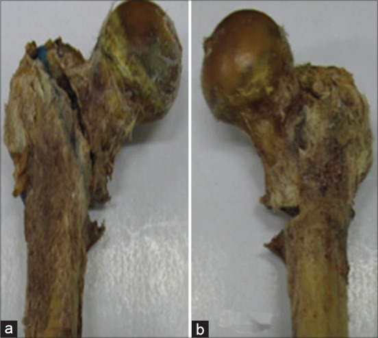
Osteotomy of cadaveric proximal femur as proposed by Krischak et al. showing an unstable trochanteric fracture in (a) anterior view and (b) posterior view
Operative procedure
One specimen from each matched pair was randomly selected for instrumentation. The PFNA II (PFNA II, Asian version, Synthes, USA) had the helical blade fixed in central position both in anteroposterior and lateral view in one group (C-C group), whereas the other group was fixed with the helical blade in inferior one-third position in anteroposterior and in central position in lateral view (I-C group) under fluoroscopic guidance. The radiographs were taken to ensure the correct placement of the tip of the helical blade at subchondral area and the measurement of the tip apex distances (TAD) was recorded [Figures 2a–d]. Specimens were shortened at the shaft to a total length of 19 cm, plotted in a specially designed frame at 25° adduction in the coronal plane and neutral in the sagittal plane to simulate one-legged stance.20 Then the specimens were stored at –20°C until mechanical testing was performed.
Figure 2.
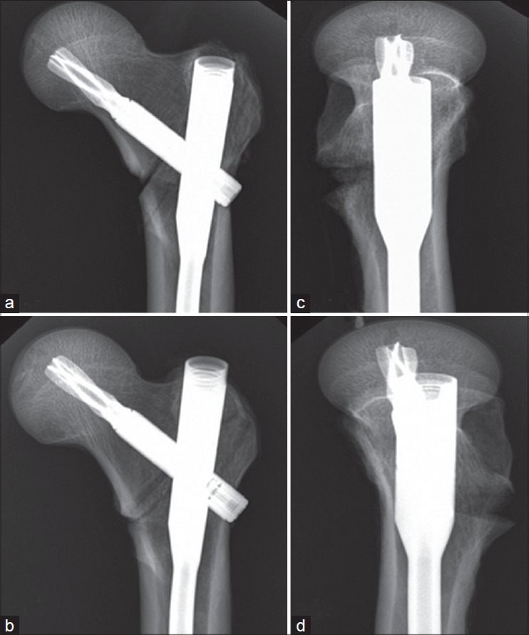
Anteroposterior and lateral radiograph of PFNA fixation in I-C group (a and b) and C-C group (c and d), respectively
Mechanical testing
Specimens were again stored at 4°C overnight and then at room temperature for at least three hours before testing. The uniaxial Bionix 858 Material Testing System (MTS, Minneapolis, Minn.) machine was used for the mechanical testing. The three metal markers which were not located collinearly, were attached closely to the blade tip inserted in the femoral head [Figure 3a]. The prepared experimental model was positioned so that it could move within the three-dimensional (3-D) space defined by the calibration frame [Figure 3b]. The motion of the femoral head in terms of angular displacement in varus direction and rotational displacement was evaluated by the optical 3-D motion tracking system (stereophotogrammetry).21 The calibration was performed to establish the laboratory co-ordinate system and to set up the calibration volume. Two image co-ordinates (x, y), which were photographed for the control point of the calibration frame, were calculated by direct linear transformation (DLT) algorithm [Figure 4].22 Each specimen was initially loaded with 750 N and allowed to come to equilibrium (120 s) before displacement measurements. The specimen was then unloaded and allowed to reach equilibrium before the measurements were repeated to determine if permanent displacement of the fracture fragments had occurred. Next, each specimen was cyclically loaded, with 750 N vertical loads applied at a rate of 3 Hz for 10, 100, 1000, and 10,000 cycles. Each specimen was allowed to reach equilibrium (120 s) after each cyclic interval, and displacement measurements both loaded and unloaded were taken.23 Finally, each specimen was axially loaded to failure recorded in load displacement curve. Failure was defined as an acute 10% or more reduction in the amount of load borne by the bone/implant construct or as a visible collapse of the device that was always evident as the first and irreversible negative slope of the load displacement curve. The cycles of loading that included implant failure were not used for the analysis of angular displacement, but only for recording load to failure.24,25
Figure 3.
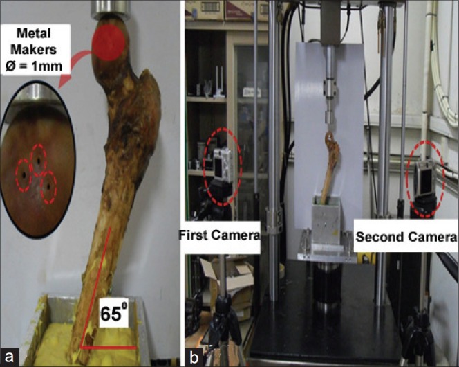
Biomechanical experimental model for three-dimensional motion analysis of the femoral head: (a) Attachment of metal markers and fixation of jig for the experimental model and (b) establishment of experimental environment for stereophotogrammetry
Figure 4.
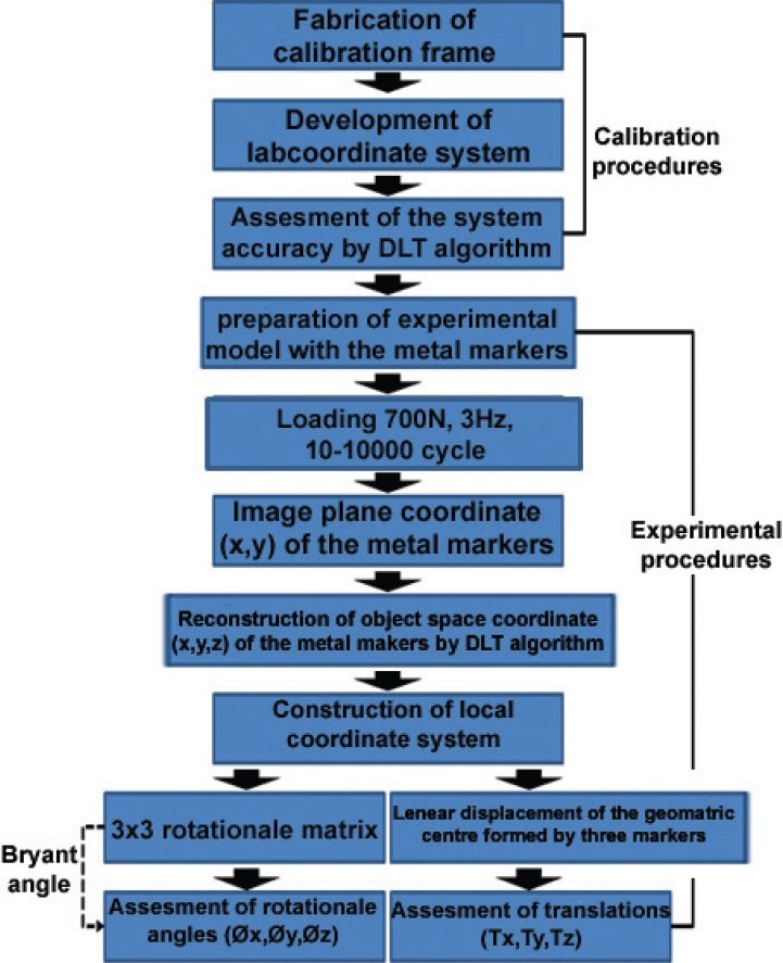
Flow diagram for the assessment of three-dimensional motion of the femoral head using stereophotogrammetry
Statistical analysis
Descriptive analysis was performed using the SPSS®, version 13.0 (SPSS Inc., Chicago, IL, USA) for Windows by calculating the mean and standard deviation for the specimens of both groups of implant. Data analysis between the groups was done using analysis of variance (ANOVA) to evaluate the relationship between fragment displacement and load-to-failure data for the two treatment groups, and fragment displacement and the number of loading cycles. Pearson correlations were performed between bone mineral density, TAD, and load to failure. A P value of <0.05 was considered to be statistically significant for all analyses.23
RESULTS
Anthropometric measurements
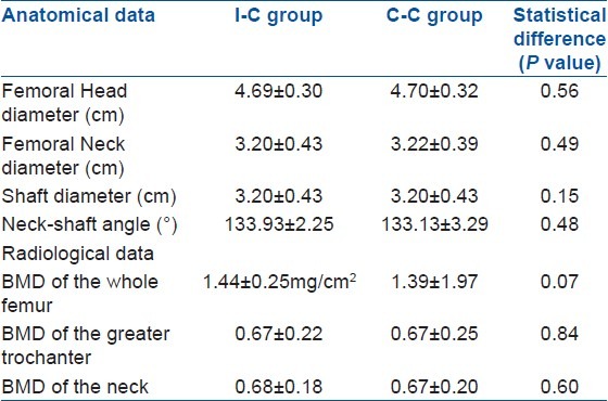
There were no statistically significant differences between the two groups for the total length of the femoral neck, diameters of the femoral neck and head, and the neck angle to the shaft [Table 1].
Table 1.
Anatomical, radiological data of specimens of I-C (inferior-central) and C-C (central-central) group
Bone mineral density
No statistically significant differences were found between the two groups. The mean value of bone mineral density of the whole proximal femur was 1.39 ± 1.57 mg/cm2 (range: 0.587–1.403 mg/cm2) in the C-C group and 1.44 ± 0.25mg/cm2 (range: 0.46–1.3 mg/cm2) in the I-C group [Table 1].
Mechanical testing
The femoral head fragment got displaced in all specimens in the same direction (varus and external rotation). The mean TAD was 22.56 mm (range: 14.84 to 30.28 mm) in the I-C group and 18.14 mm (range: 12.37 to 24.17 mm) in the C-C group. Angular displacements in the varus direction were significantly higher within the C-C group compared to the I-C group after initial loading with 750 N (P < 0.026) and after each cyclic loading (P < 0.016, P < 0.04, P < 0.038, and P < 0.039, respectively) [Table 2]. There were significantly more permanent angular displacements in the varus direction in the C-C group compared with the I-C group implant after each cyclic loading (P < 0.046, P < 0.024, P < 0.036, and P < 0.034, respectively). Rotational displacements (external rotation) were slightly higher in the C-C group compared to the I-C group in both unloaded and loaded condition after 1,000 and 10,000 cycles.(P < 0.020, P < 0.04 for unloaded and P < 0.042 and P < 0.048 for loaded states, respectively) [Table 2]. There were significantly more permanent rotational displacements (external rotation) in the C-C group compared with the I-C group after 1,000 and 10,000 cycles. (P < 0.016, P < 0.03 for unloaded and P < 0.035 and P < 0.049 for loaded states, respectively). No trends of angular displacements in the anterior direction were seen in each specimen. Loading to failure was higher in the I-C group (4462.5 ± 1750.3 N) compared to the C-C group (4175.9 ± 1652.2 N). No statistical significance was found for this parameter [Figure 3]. Regression analysis of data showed a nonlinear relationship between femoral head displacement and the number of axial loading cycles. The majority of the fracture fragment displacements occurred after the initial load, with continuation of displacements as the number of loading cycles increased, but at a decreasing rate of displacement. Correlations between bone mineral density and femoral head displacement showed a significant inverse relationship (correlation coefficient: - 0.32) with the most osteopenic specimens having the maximum displacements and the lowest loads to failure. Correlations between TAD, cyclic loading which leads to femoral head displacement, and ultimate load to failure showed a significant positive relationship [Table 3].
Table 2.
Mean fracture fragment displacement for loaded and unloaded states

Table 3.
Statiscal data (mean± standard deviation degree) and their correlation

DISCUSSION
The cause of fixation of failure of intramedullary devices in unstable intertrochanteric fractures is divided into two major groups.26–28 First, patient-related factors like osteoporotic bone is one of the main reasons for failure of fixation in the aging population.29 Second, the most important preventable factors are surgical techniques like suboptimal positioning of the implant. On reviewing the literature, we found that various studies were done for deciding the correct position of the dynamic hip screw in the femoral head. However, till today, there is no clear consensus about that. To the best of our knowledge, so far, no study has been performed about the PFNA device in terms of optimal position of the helical blade in the femoral head. In the present study, the biomechanical comparison of the stability of a PFNA device in terms of two positions of the helical blade in the femoral head revealed significantly more stability in the I-C group than the C-C group. Load to failure was higher in the I-C group compared to the C-C group, but a statistically significant difference was not found.
In unstable fractures, the lesser trochanter and part of calcar femorale are missing from the mechanical load transmission system and because of the lack of bony support over the medial aspect of femur, the proximal fragment easily collapses (varus) and internally rotates under the physiologic loads.30 The inferior placements of helical blades in the frontal plane and centrally in the sagittal plane inherently support the comminuted posteromedial cortex and allow compaction of fracture suface, shortening the lever arm, decreasing the bending moment, thus avoiding cutout of screw from the femoral head. The inferior placements of the helical blade achieve the medial-most position in the subchondral area, and thus, the stress-bearing surface area of the helical blade increases. In this way, the inferiorly placed helical blade withstands more force than the centrally placed helical blade for angular displacement in varus position and load to failure.31 The central location of a helical blade on the anteroposterior view has no resultant force to affect the femoral head for internal or external rotation. However, inferior location of a helical blade has the ability to rotate the femoral head externally. Consequently, the inferior insertion of a helical blade can withstand the deforming force which is responsible for rotational displacement and achieves a better result.16,31
The inferior central placements of the screw helps in better control of the proximal fragment because the pattern of bone architecture which is formed by the decussation of compression and tensile trabeculae provide strong anchorage.14 Although this peripheral placement of the helical blade increases the TAD, the TAD is not related with cutout failure.32 In our study, the mean TAD in the I-C group was more than the C-C group and TAD had a positive linear correlation with cyclic loading which leads to fracture displacement and ultimate load to failure.16,31–33
This study has several limitations. In general, like other cadaveric studies, results should not be applied to complex in vivo loading situations without consideration. First, the osteotomy was performed using a hand saw producing flat bony interfaces, whereas fractures in patients usually have irregular surfaces. However, the flat surfaces of the fracture fragments at the osteotomy site did allow us to assess the true fixation stability by the implant alone rather than the stability contributed by the interdigitating well reduced fracture fragments. Moreover, all the soft tissue was removed from bone for standardization which is not the case in real patients. This study was carried out on cadaveric femurs which were normal in architecture. Hence, the significant morphological changes resulting from fracture healing like bone callus formation, remodeling, subtle malreduction, and femoral neck shortening could not be studied. The number of specimens was small. This study requires large number of specimens for better relevant evaluation of statistical data. In this study, we chose a relatively simple reproducible loading protocol, though we acknowledge that physiologic loading during activity is more complex because of various forces acting on the proximal femur.
In conclusion, this is the first biomechanical study of a PFNA device in terms of two common positions of a helical blade in the femoral head. Our in vitro study result suggests that the inferior position of the helical blade in the frontal plane and central position in the sagittal plane is superior to the C-C position and provides better biomechanical stability for angular and rotational displacement in unstable intertrochanteric fractures. We see this study as a stimulus for further experimental studies with larger specimens and complex loading protocols.
Footnotes
Source of Support: Nil
Conflict of Interest: None.
REFERENCES
- 1.Burge R, Dawson-Hughes B, Solomon DH, Wong JB, King A, Tosteson A. Incidence and economic burden of osteoporosis-related fractures in the United States, 2005-2025. J Bone Miner Res. 2007;22:465–75. doi: 10.1359/jbmr.061113. [DOI] [PubMed] [Google Scholar]
- 2.Penzkofer J, Mendel T, Bauer C, Brehme K. Treatment results of pertrochanteric and subtrochanteric femoral fractures: A retrospective comparison of PFN and PFNA. Unfallchirurg. 2009;112:699–705. doi: 10.1007/s00113-009-1642-x. [DOI] [PubMed] [Google Scholar]
- 3.Mahomed N, Harrington I, Kellam J, Maistrelli G, Hearn T, Vroemen J. Biomechanical analysis of the Gamma nail and sliding hip screw. Clin Orthop Relat Res. 1994;304:280–8. [PubMed] [Google Scholar]
- 4.Kold S, Bechtold JE, Mouzin O, Elmengaard B, Chen X, Soballe K. Fixation of revision implants is improved by a surgical technique to crack the sclerotic bone rim. Clin Orthop Relat Res. 2005;432:160–6. doi: 10.1097/01.blo.0000149815.78598.ea. [DOI] [PubMed] [Google Scholar]
- 5.Mereddy P, Kamath S, Ramakrishnan M, Malik H, Donnachie N. The AO/ASIF proximal femoral nail antirotation (PFNA): A new design for the treatment of unstable proximal femoral fractures. Injury. 2009;40:428–32. doi: 10.1016/j.injury.2008.10.014. [DOI] [PubMed] [Google Scholar]
- 6.Audige L, Hanson B, Swiontkowski MF. Implant-related complications in the treatment of unstable intertrochanteric fractures: Meta-analysis of dynamic screw-plate versus dynamic screw-intramedullary nail devices. Int Orthop. 2003;27:197–203. doi: 10.1007/s00264-003-0457-6. [DOI] [PMC free article] [PubMed] [Google Scholar]
- 7.Bonnaire F, Weber A, Bosl O, Eckhardt C, Schwieger K, Linke B. “Cutting out” in pertrochanteric fractures-problem of osteoporosis? Unfallchirurg. 2007;110:425–32. doi: 10.1007/s00113-007-1248-0. [DOI] [PubMed] [Google Scholar]
- 8.Baumgaertner MR, Curtin SL, Lindskog DM, Keggi JM. The value of the tip-apex distance in predicting failure of fixation of peritrochanteric fractures of the hip. J Bone Joint Surg Am. 1995;77:1058–64. doi: 10.2106/00004623-199507000-00012. [DOI] [PubMed] [Google Scholar]
- 9.Davis TR, Sher JL, Horsman A, Simpson M, Porter BB, Checketts RG. Intertrochanteric femoral fractures. Mechanical failure after internal fixation. J Bone Joint Surg Br. 1990;72:26–31. doi: 10.1302/0301-620X.72B1.2298790. [DOI] [PubMed] [Google Scholar]
- 10.Parker MJ. Cutting-out of the dynamic hip screw related to its position. J Bone Joint Surg Br. 1992;74:625. doi: 10.1302/0301-620X.74B4.1624529. [DOI] [PubMed] [Google Scholar]
- 11.Den Hartog BD, Bartal E, Cooke F. Treatment of the unstable intertrochanteric fracture. Effect of the placement of the screw, its angle of insertion, and osteotomy. J Bone Joint Surg Am. 1991;73:726–33. [PubMed] [Google Scholar]
- 12.Galanakis IA, Steriopoulos KA, Dretakis EK. Correct placement of the screw or nail in trochanteric fractures. Effect of the initial placement in the migration. Clin Orthop Relat Res. 1995;313:206–13. [PubMed] [Google Scholar]
- 13.Lindskog DM, Baumgaertner MR. Unstable intertrochanteric hip fractures in the elderly. J Am Acad Orthop Surg. 2004;12:179–90. doi: 10.5435/00124635-200405000-00006. [DOI] [PubMed] [Google Scholar]
- 14.Kaufer H. Mechanics of the treatment of hip injuries. Clin Orthop Relat Res. 1980;146:53–61. [PubMed] [Google Scholar]
- 15.Laskin RS, Gruber MA, Zimmerman AJ. Intertrochanteric fractures of the hip in the elderly: A retrospective analysis of 236 cases. Clin Orthop Relat Res. 1979;141:188–95. [PubMed] [Google Scholar]
- 16.Wu CC, Shih CH. Biomechanical analysis of the dynamic hip screw in the treatment of intertrochanteric fractures. Arch Orthop Trauma Surg. 1991;110:307–10. doi: 10.1007/BF00443464. [DOI] [PubMed] [Google Scholar]
- 17.Thomas AP. Dynamic hip screws that fail. Injury. 1991;22:45–6. doi: 10.1016/0020-1383(91)90161-7. [DOI] [PubMed] [Google Scholar]
- 18.Leung KS, So WS, Shen WY, Hui PW. Gamma nails and dynamic hip screws for peritrochanteric fractures. A randomised prospective study in elderly patients. J Bone Joint Surg Br. 1992;74:345–51. doi: 10.1302/0301-620X.74B3.1587874. [DOI] [PubMed] [Google Scholar]
- 19.Krischak GD, Augat P, Beck A, Arand M, Baier B, Blakytny R, et al. Biomechanical comparison of two side plate fixation techniques in an unstable intertrochanteric osteotomy model: Sliding hip screw and percutaneous compression plate. Clin Biomech (Bristol, Avon) 2007;22:1112–8. doi: 10.1016/j.clinbiomech.2007.07.016. [DOI] [PubMed] [Google Scholar]
- 20.Bergmann G, Deuretzbacher G, Heller M, Graichen F, Rohlmann A, Strauss J, et al. Hip contact forces and gait patterns from routine activities. J Biomech. 2001;34:859–71. doi: 10.1016/s0021-9290(01)00040-9. [DOI] [PubMed] [Google Scholar]
- 21.Pourcelot P, Audigie F, Degueurce C, Geiger D, Denoix JM. A method to synchronise cameras using the direct linear transformation technique. J Biomech. 2000;33:1751–4. doi: 10.1016/s0021-9290(00)00132-9. [DOI] [PubMed] [Google Scholar]
- 22.Cole GK, Nigg BM, Ronsky JL, Yeadon MR. Application of the joint coordinate system to 3-dimensional joint attitude and movement representation - a standardization proposal. J Biomech Eng. 1993;115:344–9. doi: 10.1115/1.2895496. [DOI] [PubMed] [Google Scholar]
- 23.Strauss E, Frank J, Lee J, Kummer FJ, Tejwani N. Helical blade versus sliding hip screw for treatment of unstable intertrochanteric hip fractures: A biomechanical evaluation. Injury. 2006;37:984–9. doi: 10.1016/j.injury.2006.06.008. [DOI] [PubMed] [Google Scholar]
- 24.Apel DM, Patwardhan A, Pinzur MS, Dobozi WR. Axial loading studies of unstable intertrochanteric fractures of the femur. Clin Orthop Relat Res. 1989;246:156–64. [PubMed] [Google Scholar]
- 25.Roderer G, Moll S, Gebhard F, Claes L, Krischak G. Side plate fixation vs.intramedullary nailing in an unstable medial femoral neck fracture model: A comparative biomechanical study. Clin Biomech (Bristol, Avon) 2011;26:141–6. doi: 10.1016/j.clinbiomech.2010.09.020. [DOI] [PubMed] [Google Scholar]
- 26.Larsson S, Friberg S, Hansson LI. Trochanteric fractures. Influence of reduction and implant position on impaction and complications. Clin Orthop Relat Res. 1990;259:130–9. [PubMed] [Google Scholar]
- 27.Swiontkowski MF, Harrington RM, Keller TS, Van Patten PK. Torsion and bending analysis of internal fixation techniques for femoral neck fractures: The role of implant design and bone density. J Orthop Res. 1987;5:433–44. doi: 10.1002/jor.1100050316. [DOI] [PubMed] [Google Scholar]
- 28.Madsen JE, Naess L, Aune AK, Alho A, Ekeland A, Stromsoe K. Dynamic hip screw with trochanteric stabilizing plate in the treatment of unstable proximal femoral fractures: A comparative study with the Gamma nail and compression hip screw. J Orthop Trauma. 1998;12:241–8. doi: 10.1097/00005131-199805000-00005. [DOI] [PubMed] [Google Scholar]
- 29.Barrios C, Brostrom LA, Stark A, Walheim G. Healing complications after internal fixation of trochanteric hip fractures: The prognostic value of osteoporosis. J Orthop Trauma. 1993;7:438–42. doi: 10.1097/00005131-199310000-00006. [DOI] [PubMed] [Google Scholar]
- 30.Zafiropoulos G, Pratt DJ. Fractured Gamma nail. Injury. 1994;25:331–6. doi: 10.1016/0020-1383(94)90248-8. [DOI] [PubMed] [Google Scholar]
- 31.Wu CC, Shih CH, Lee MY, Tai CL. Biomechanical analysis of location of lag screw of a dynamic hip screw in treatment of unstable intertrochanteric fracture. J Trauma. 1996;41:699–702. doi: 10.1097/00005373-199610000-00017. [DOI] [PubMed] [Google Scholar]
- 32.Guven M, Yavuz U, Kadioglu B, Akman B, Kilinçoğlu V, Unay K, et al. Importance of screw position in intertrochanteric femoral fractures treated by dynamic hip screw. Orthop Traumatol Surg Res. 2010;96:21–7. doi: 10.1016/j.rcot.2009.11.004. [DOI] [PubMed] [Google Scholar]
- 33.Jacobs RR, McClain O, Armstrong HJ. Internal fixation of intertrochanteric hip fractures: A clinical and biomechanical study. Clin Orthop Relat Res. 1980;146:62–70. [PubMed] [Google Scholar]


