Abstract
A new and simple method for fabrication of nanofiber scaffolds with gradations in fiber organization is reported. The nanofiber organization, achieved by deposition of random fibers on the uniaxially-aligned nanofiber mat in a gradient manner, directed morphological changes of applied adipose-derived stem cells. These morphological changes and resultant biochemical changes can help mimic the structural orientation of complex biomechanical structures like the collagen fiber structure at the tendon-to-bone insertion site. In addition, chemical gradients can be established through nanoencapsulation in this novel scaffold allowing for enhanced biomedical applications.
Keywords: Electrospinning, Gradient, Nanofibers, Organization, Tendon-to-Bone
Introduction
Surfaces with morphology and/or chemical composition that vary over a certain length may result in a gradual change in physical and/or chemical properties.[1] Such surfaces may represent a unique platform for the high-throughput investigations in many areas ranging from fundamental to industrial applications. Notable examples include the use of gradients for studying wettability effects, protein adsorption and cell response. One previous study demonstrated that rat calvarial osteoblasts proliferated much faster on the surface with higher roughness and the projection area of osteoblasts increase considerably as the roughness decreased on the aluminum surface with gradation in roughness.[2,3] A separate study demonstrated that on a surface with silica particle-density gradients, the same type of cells displayed a dramatic decrease in proliferation at locations with higher particle coverage and spreading and formation of a strong actin network was hindered at locations with maximum particle density while cells spread well and developed a well-organized actin network in the absence of particles.[4,5]
However, the morphological gradients reported previously were mostly related to surface roughness.[6–10] In some practical biomedical application, other types of morphological gradients may be required.[11] It is known that tendons are attached to bones across a specialized transitional tissue with varying structures (i.e., collagen fibers are less oriented at the insertion compared to the tendon) and compositions (i.e., the relative mineral concentration vs. distance across the insertion site shows an approximately linear increase across the interface.).[12–15] Efforts have been devoted to the development of scaffolds which could mimic the structure (i.e., collagen fiber orientation) and/or composition (i.e., mineral content) of tendon-to-bone insertions for the repair of rotator cuff injury. A number of studies demonstrated the fabrication of scaffolds with a gradient of mineral content for mimicking the composition and mechanical function of the interface between soft tissue to hard tissue (i.e., tendon-to-bone, ligament-to-bone, and cartilage-to-bone).[16–18] However, few studies have centered on the creation of scaffolds capable of exhibiting the unique structural organization of collagen fibers seen at the native tendon-to-bone insertion site except that a recent study attempted to fabricate “aligned-to-random” nanofiber scaffolds by making use of a specially-designed collector during electrospinning for mimicking the structure of the tendon-to-bone insertion site.[19] But some issues still remain in this study: the nanofiber scaffold has no gradual transitions from aligned portion to random portion; and there is apparent difference of the thicknesses between the two portions, which could easily cause breaking at the interface upon exerting a force. Therefore, so far no such a scaffold can fully recreate the gradients in structure found at the uninjured tendon-to-bone attachment.
In this work, we report a new and simple method for fabrication of nanofiber scaffolds with gradations in fiber organization by depositing random fibers on the uniaxially-aligned nanofiber mat in a gradient manner. These surfaces mimic the change in fiber orientation which presents at the tendon-to-bone insertion site. Tailoring the surface features in a user-specified manner can provide spatial control over cell response like cell morphology.[20] Hence, we hypothesize that adipose-derived stem cells (ADCSs) could respond differently to different locations of such nanofiber surfaces. An adipose tissue is one of the sources of mesenchymal stem cells and ADSCs are very similar in nature to bone mesenchymal stem cells (BMSCs) in terms of multipotency.[21, 22] Adipose tissue is abundant in most individuals and can be harvested using a simple liposuction procedure which is less invasive and cause less discomfort and donor-site damage.[23] In addition, adipose tissue has a significantly higher stem cell density then does bone marrow (5% vs 0.01%). ADSCs have been demonstrated for use in bone, cartilage, and tendon tissue engineering and are used in this study.[24–28]
Experimental Section
Fabrication and Characterization of Nanofiber Scaffolds
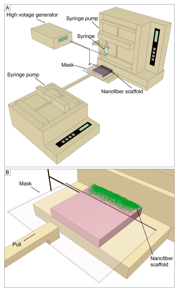
The uniaxially-aligned nanofibers were produced by electrospinning using an air-gap collector based on previous studies.[29, 30] Poly(ε-caprolactone) (PCL) (Mw=80,000 g/mol; Sigma-Aldrich, St. Louis, MO) was dissolved in a solvent mixture consisting of dichloromethane (DCM) and N, N-dimethylformamide (DMF) (Fisher Chemical, Waltham, MA) with a ratio of 4:1 (v/v) at a concentration of 10% (w/v). Polymer solution was pumped at a flow rate of 0.5 mL/h using a syringe pump. A dc high voltage of 12 kV was applied between the nozzle and a grounded air-gap collector made of aluminum foil (with an open void 2 cm × 5 cm). Subsequently, the uniaxially-aligned nanofibers were easily transferred to a glass slide. Nanofiber scaffolds were fabricated using the setup shown in Figure 1. Briefly, a glass slide covered with uniaxially-aligned nanofibers served as a collector. A movable plastic mask was connected to a second syringe pump and placed 2 mm above the collector during deposition of random fibers. In order to demonstrate the encapsulation of functional molecules, coumarin 6 (Sigma-Aldrich, St. Louis, MO) (1% w/w) was added to the polymer solution prior to electrospinning.
Figure 1.
Schematic illustrating (A) the setup for fabrication of nanofiber scaffolds with gradations in fiber organization and (B) the close-up view of the collector. The mask is pulled at 1mm per minute.
The morphology of nanofiber scaffolds were characterized by scanning electron microscopy (SEM) (FEI, Nova 2300, Oregon). To avoid charging, polymer fiber samples were fixed on a metallic stud with double-sided conductive tape and coated with platinum for 40 seconds in vacuum at a current intensity of 40 mA using a sputter coater. SEM image were acquired at an accelerating voltage of 15 kV.
FFT analysis was performed by utilizing the FFT function of the Scion Image processing software. The detailed information on measuring fiber alignment by FFT can refer to an excellent paper.[31] The spatial information presented by an image can be processed into a mathematically defined frequency domain using 2D FFT function. The frequency domain maps the rate where pixel intensities vary in the spatial domain. Pixel intensities and the intensity distribution of the resulting image corresponds to the directional content of the original image, and the results of the FFT yield frequencies orthogonal to those in the original image.[32–34]
Adipose-derived Stem Cell Culture and Characterization
Human ADSCs were obtained from Cellular Engineering Technologies (Coralville, IA) and were cultured in α-modified Eagle’s medium (α-MEM) supplemented with 10% fetal bovine serum (FBS, Invitrogen) and 1% gentalmycine/streptomycin (Invitrogen) at 37 °C in an atmosphere of 95% air/5% CO2. Cell culture medium was changed every 2 days. Prior to cell seeding to nanofiber scaffolds, cells were trypsinized and counted. Around 1×10⁴ cells were seeded on each nanofiber scaffold without encapsulation of coumarin 6. After incubation for 3 day and 7 days, live cells were stained using fluorescein diacetate (Sigma-Aldrich, St. Louis, MO). Fluorescent images were taken using a fluorescence microscope (Zeiss, Thornwood, NY, USA). ADSCs morphology was qualitatively assessed using acquired images, while the cell orientation was quantitatively examined through the use of a custom MATLAB program (MathWorks, Inc., Natick, MA), described previously.[35] Each experiment was performed with three scaffolds and three images were taken and analyzed at each location of the scaffold. The distributions of cell angles at different locations of nanofiber scaffolds was carried out using the Kolmogorov-Smirnov test based on a similar statistical analysis employed in one previous study.[36]
Chemical Gradient Formation
In order to demonstrate the formation of chemical/biological gradient, 1% (w/w) of coumarin 6 dye was added to the polymer solution prior to electrospinning. Coumarin 6 was uniformly encapsulated throughout nanofibers during electrospinning process. Coumarin 6-loaded, random fibers were deposited in a gradient fashion on a glass slide instead of a uniaxially aligned nanofiber mat. For coumarin 6-labeled nanofibers, fluorescent images were taken using a fluorescence microscope (Zeiss). The fluorescent intensity was quantified by measuring the grey scale using ImageJ software (NIH).
Results and Discussion
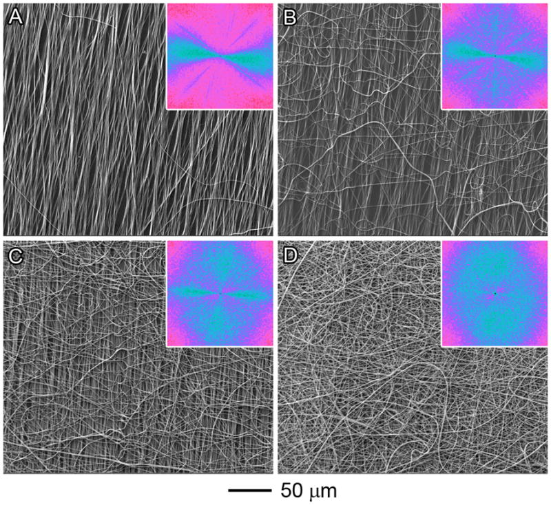
Nanofiber scaffolds with gradations in fiber organization were generated by deposition of random fibers on an uniaxially-aligned nanofiber mat (Figure 1). It is observed that more and more random fibers were deposited from 0 mm to 6 mm along the nanofiber scaffold (Figure 2). The Fourier fast transfer (FFT) patterns suggest progression of random fiber generation from 0 to 6 mm (Figures 2A–2D). In particular the FFT pattern at 6 mm suggests randomly oriented nanofibers.
Figure 2.

SEM images of PCL nanofiber scaffolds at different locations: (A) 0 mm; (B) 2 mm; (C) 4 mm; and (D) 6 mm. The insets show the FFT patterns of the corresponding images. For (D), the FFT pattern suggests that the nanofibers were randomly oriented. The pixel intensities (light blue color) were independent of direction with the uniaxially-aligned nanofiber mat fully covered by the deposited random fibers.
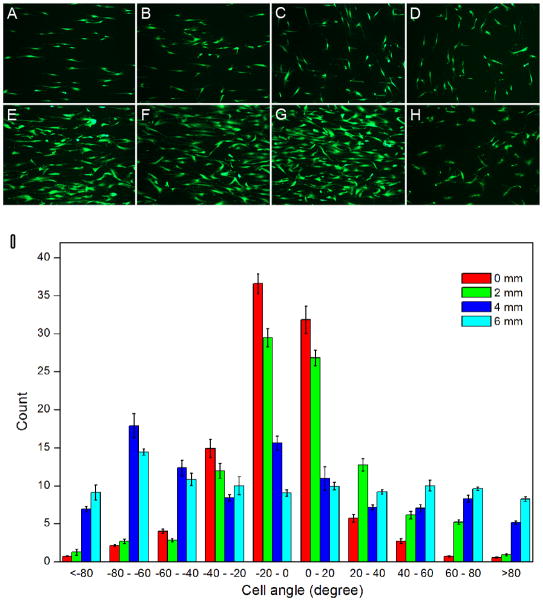
Once we demonstrated successful generation of random fiber deposition, we studied whether this gradient fiber orientation can direct morphological changes following incubation with ADSCs. Scaffolds generated using the techniques above were incubated with ADSCs for 3 and 7 days. Live cells were detected using a fluorescein diacetate (FDA) assay (Figure 3, A–H), The response of pre-seeded ADSCs to underlying nanofiber scaffolds was quantified by measuring the orientation of individual cells relative to the long axis of the fibers (Figure 3I). The distribution of cell orientations demonstrated that ADSCs seeded on random nanofibers lacked organization and directional specificity, as the cells projected in all possible directions. In contrast, ADSCs seeded on the aligned scaffolds demonstrated orientation and alignment along the fibers in contact with the cells. In these cases, approximately 70% of the cells were oriented within 20°of the axis of nanofiber alignment. Comparison of the distributions of ADSCs orientations on the various portions of scaffolds using the Kolmogorov-Smirnov test further confirmed that the pattern of cellular orientation observed at different portions (distance > 4 mm) on the nanofiber scaffolds was significantly different (p < 0.05).
Figure 3.
Fluorescein diacetate assay: Adipose-derived stem cells after incubation for 3 days (AD) and 7 days (E–H) showing different morphologies on different locations of nanofiber scaffolds with gradations in fiber organizations (A, E): 0 mm; (B, F): 2 mm; (C, G): 4 mm; and (D, H): 6 mm. (I): Quantitative analysis of morphology of adipose-derived stem cells on different locations of nanofiber scaffolds after incubation for 3 days. Compared to the distributions of cell angle at different locations using the Kolmogorov-Smirnov test, p values of 0.007 (between 0 mm and 6 mm), 0.675 (between 0 mm and 2 mm), 0.031 (between 0 mm and 4 mm), 0.031 (between 2 mm and 6 mm), 0.11 (between 2 mm and 4 mm), and 0.111 (between 4 mm and 6 mm) were obtained. p < 0.05 indicates significant difference.
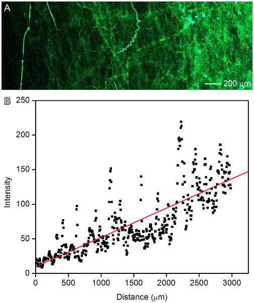
To broaden potential biomedical applications, chemical gradients were established on this novel scaffold using nanoencapsulation. Coumarin 6-loaded random PCL nanofibers were generated in gradient fashion and shown in Figure 4A. We quantified the fluorescence intensity by measuring the grey scale using Image J software (Figure 4B). It is observed that the fluorescent intensity increased along the distance. This method could be readily extended to fabricate two-component gradients on the surface by depositing random fibers twice in two different directions.
Figure 4.
(A): Fluorescence microscopy image illustrating the deposition time of random PCL electrospun nanofibers loaded with coumarin 6 on glass slides. The fluorescent intensity increased from left to right as quantified by ImageJ software (B).
It was reported that there is a transition of collagen fiber organization at the tendon-to-bone insertion site.[12–14] Although one previous study attempted to generate “random-to-aligned” nanofiber scaffolds to mimic the structure of the insertion, [19] the current work represented the first report of the fabrication of nanofiber scaffolds with a gradual transition in fiber organization on the surface. In this study, we have demonstrated the preparation of scaffolds with a gradient in fiber orientation at a length scale of millimeter, which is in the same scale of native tendon-to-bone region.[12] It is reasoned that the gradations of fiber organization could be readily tailored by changing the pulling speed of mask and other operating parameter of electrospinning (i.e., flow rate and polymer concentration). In addition, the nanofiber scaffolds can be decorated with other desirable molecules to illicit certain function through either encapsulation or surface modification (Figure S1). Owing to the gradation in fiber organization, the scaffolds fabricated in this study may regulate the distribution of secreted extracellular matrix proteins of seeded cells like the orientation of collagen fibrils.[37] It is believed that the reduced fiber alignment along the tendon-to-bone insertion site reduces tissue stiffness.[12] Therefore, such a scaffold may be useful for the generation of functional tissues with mechanical gradient, which is in particular valuable for the load transfer without damaging stress concentrations at the tendon-to-bone insertion site.[38]
Recent studies demonstrated aligned nanofiber scaffolds can provide nanotopographic cues and influence cellular activities (i.e., migration, proliferation, and differentiation).[39–41] The aligned nanofibers/threads could induce teno-lineage differentiation of human tendon stem/progenitor cells or human mesenchymal stem cells evidenced by a significant up-regulation of tendon-specific markers (i.e., scleraxis, tenomdulin, runx2) and simultaneously a specific marker of bone like osteocalcin could be suppressed to a great extent on the same scaffolds.[40,41] In contrast, randomly oriented nanofibers/threads could induce osteogenesis as indicated by the increased expression of bone markers including osteocalcin and alkaline phosphate with increasing incubation time. The nanofiber scaffolds developed in the present study have continuous gradations in the fiber orientation, which could regulate cell behaviors differently at different locations of scaffolds. We can hypothesize that ADSCs may differentiate into tendon fibroblasts and osteoblasts at the aligned and random end, respectively. In addition, ADSCs may differentiate into chondrocytes between the two ends. We will perform the detailed study to investigate the differentiation of ADSCs on such a scaffold in the future work.
Although the gradient in the present work is continuous, we believe that it is also possible to fabricate the gradient in discrete steps by controlling the movement of the mask. We also demonstrated that the nanofiber surface with chemical gradients can be readily formed by encapsulation of desired materials inside nanofibers. Such surfaces could be useful as a substrate in various fundamental and practical biomedical applications including study of cellular behavior, high throughput screening, and design of implants/implant coatings.[20] Bone morphogenetic protein 2 (BMP2) plays an important role in the development of bone and cartilage and has been demonstrated to potently induce osteoblast differentiation in many cell types. By making use of the same principle of the formation of coumarin 6 gradient, BMP2 gradient can be readily formed on the uniaxially aligned nanofiber mat. At the random end, the scaffolds may have large content of BMP2, which can enhance the osteogenic differentiation in conjunction with the topographic cues imparted by the randomly oriented fibers. The aligned end of scaffolds is lack of BMP2, which may have no influences on the tendon lineage differentiation.
It is known that tendon-to-bone insertion can be divided by four zones: tendon, fibrocartilage, mineralized fibrocartilage, and bone.[42] The mineral content along the insertion site increases linearly.[14, 15] In future studies, we will mineralize this scaffold with a gradient fashion (i.e., random portion has high content of minerals and aligned portion has no minerals), which could closely mimic both the structure and composition of tendon-to-bone insertion site. [16]
Conclusion
In summary, we have demonstrated a simple, robust and facile method to fabricate nanofiber scaffolds with gradations in fiber organization, which could potentially mimic the structure (i.e., collagen fiber organization) at tendon-to-bone insertion site. We also demonstrated that ADSCs seeded on such a scaffold exhibited different morphologies at different locations. In addition, we demonstrated the formation of nanofiber surfaces with chemical gradients through encapsulation of desired materials inside deposited nanofibers. By incorporating mineral gradient to this scaffold, it could be used to recapitulate both structure and composition of tendon-to-bone insertion site to a considerable degree, which may be promising for the repair of tendon-to-bone insertion.
Supplementary Material
Fluorescence microscopy images of nanofiber scaffolds at different locations: (A) 0 mm; (B) 2 mm; (C) 4 mm; and (D) 6 mm. Coumarin 6 was uniformly encapsulated throughout nanofibers in green color during electrospinning process.
Acknowledgments
This work was supported in part by grant number UL1RR033173 from the National Center for Research Resources (NCRR), funded by the office of the Director, National Institutes of Health (NIH) and supported by the NIH roadmap for Medical Research and start-up funds from Marshall Institute for Interdisciplinary Research and Center for Diagnostic Nanosystems at Marshall University.
Contributor Information
Jingwei Xie, Marshall Institute for Interdisciplinary Research and Center for Diagnostic Nanosystems, Marshall University, Huntington, WV 25755 USA.
Bing Ma, Marshall Institute for Interdisciplinary Research and Center for Diagnostic Nanosystems, Marshall University, Huntington, WV 25755 USA.
Praveesuda Lorwattanapongsa Michael, Marshall Institute for Interdisciplinary Research and Center for Diagnostic Nanosystems, Marshall University, Huntington, WV 25755 USA.
Franklin D. Shuler, Department of Orthopaedic Surgery, Joan C. Edwards School of Medicine, Marshall University, Huntington, WV 25701 USA
References
- 1.Morgenthaler S, Zink C, Spencer ND. Soft Matt. 2008;4:419. doi: 10.1039/b715466f. [DOI] [PubMed] [Google Scholar]
- 2.Kunzler TP, Drobek T, Schuler M, Spencer ND. Biomaterials. 2007;28:2175. doi: 10.1016/j.biomaterials.2007.01.019. [DOI] [PubMed] [Google Scholar]
- 3.Kunzler TP, Drobek T, Sprecher CM, Schuler M, Spencer ND. Appl Surf Sci. 2006;253:2148. [Google Scholar]
- 4.Kunzler TP, Huwiler C, Drobek T, Voros J, Spencer ND. Biomaterials. 2007;28:5000. doi: 10.1016/j.biomaterials.2007.08.009. [DOI] [PubMed] [Google Scholar]
- 5.Huwiler C, Kunzler TP, Textor M, Voros J, Spencer ND. Langmuir. 2007;23:5929. doi: 10.1021/la0700422. [DOI] [PubMed] [Google Scholar]
- 6.Simon CG, Jr, Lin-Gibson S. Adv Mater. 2011;23:369. doi: 10.1002/adma.201001763. [DOI] [PubMed] [Google Scholar]
- 7.Li X, MacEwan MR, Xie J, Siewe D, Yuan X, Xia Y. Adv Funct Mater. 2010;20:1632. doi: 10.1002/adfm.201000146. [DOI] [PMC free article] [PubMed] [Google Scholar]
- 8.Zhang J, Xue L, Han Y. Langmuir. 2005;21:5. doi: 10.1021/la047584t. [DOI] [PubMed] [Google Scholar]
- 9.Fujiki D, Jing C, Can-Pham DT, Nakanishi H, Norisuye T, Tran-Cong-Miyata Q. Adv Nat Sci: Nanosci, Nanotechnol. 2010;1:043003. [Google Scholar]
- 10.Nakanishi H, Namikawa N, Norisuye T, Tran-Cong-Miyata Q. Soft Matt. 2006;2:149. doi: 10.1039/b514887a. [DOI] [PubMed] [Google Scholar]
- 11.Seidi A, Ramalingam M, Elloumi-Hannachi I, Ostrovidov S, Khademhosseini A. Acta Biomater. 2011;7:1441. doi: 10.1016/j.actbio.2011.01.011. [DOI] [PubMed] [Google Scholar]
- 12.Genin GM, Kent A, Birman V, Wopenka B, Pasteris JD, Marquez JP, Thomopoulos S. Biophy J. 2009;97:976. doi: 10.1016/j.bpj.2009.05.043. [DOI] [PMC free article] [PubMed] [Google Scholar]
- 13.Thomopoulos S, Marquez JP, Weinberger B, Birman V, Genin GM. J Biomech. 2006;39:1842. doi: 10.1016/j.jbiomech.2005.05.021. [DOI] [PubMed] [Google Scholar]
- 14.Thomopoulos S, Williams GR, Gimbel JA, Favata M, Soslowsky LJ. J Orthopaedic Res. 2003;21:413. doi: 10.1016/S0736-0266(03)00057-3. [DOI] [PubMed] [Google Scholar]
- 15.Thomopoulos S, Genin GM, Galatz LM. J Musculoskelet Neuronal Interact. 2010;10:35. [PMC free article] [PubMed] [Google Scholar]
- 16.Li X, Xie J, Lipner J, Yuan X, Thomopoulos S, Xia Y. Nano Lett. 2009;9:2763–2768. doi: 10.1021/nl901582f. [DOI] [PMC free article] [PubMed] [Google Scholar]
- 17.Lu C, Han Z, Czernuszka JT. Acta Biomater. 2009;5:661. doi: 10.1016/j.actbio.2008.09.022. [DOI] [PubMed] [Google Scholar]
- 18.Samavedi S, Horton CO, Guelcher SA, Goldstein AS, Whittington AR. Acta Biomater. 2011 doi: 10.1016/j. actbio.2011.07.008. [DOI] [PubMed] [Google Scholar]
- 19.Xie J, Li X, Lipner J, Manning CN, Schwartz AG, Thomopoulos S, Xia Y. Nanoscale. 2010;2:923. doi: 10.1039/c0nr00192a. [DOI] [PMC free article] [PubMed] [Google Scholar]
- 20.Singh M, Berkland C, Detamore MS. Tissue Eng B. 2008;14:341. doi: 10.1089/ten.teb.2008.0304. [DOI] [PMC free article] [PubMed] [Google Scholar]
- 21.Gimble JM, Guilak F. Cytotherapy. 2003;5:362. doi: 10.1080/14653240310003026. [DOI] [PubMed] [Google Scholar]
- 22.Zuk PA, Zhu M, Mizuno H, Huang J, Futrell JW, Katz AJ, Benhaim P, Lorenz HP, Hedrick MH. Tissue Eng. 2001;7:211. doi: 10.1089/107632701300062859. [DOI] [PubMed] [Google Scholar]
- 23.Palpant NJ, Metzger JM. Curr Stem Cell Res Ther. 2010;5:145. doi: 10.2174/157488810791268654. [DOI] [PMC free article] [PubMed] [Google Scholar]
- 24.Cowan CM, Shi YY, Aalami OO, Chou YF, Mari C, Thomas R, Quarto N, Contag CH, Wu B, Longaker MT. Nat Biotech. 2004;22:560. doi: 10.1038/nbt958. [DOI] [PubMed] [Google Scholar]
- 25.James R, Kumbar SG, Laurencin CT, Balian G, Chhabra AB. Biomed Mater. 2011;6:025011. doi: 10.1088/1748-6041/6/2/025011. [DOI] [PMC free article] [PubMed] [Google Scholar]
- 26.Bodle JC, Hanson AD, Loboa EG. Tissue Eng B. 2011;17:195. doi: 10.1089/ten.teb.2010.0738. [DOI] [PMC free article] [PubMed] [Google Scholar]
- 27.Tapp H, Hanley EN, Jr, Patt JC, Gruber HE. Exp Biol Med. 2009;234:1. doi: 10.3181/0805/MR-170. [DOI] [PubMed] [Google Scholar]
- 28.Lee JH, Rhie JW, Oh DY, Ahn ST. Biochem Biophy Res Commun. 2008;370:456. doi: 10.1016/j.bbrc.2008.03.123. [DOI] [PubMed] [Google Scholar]
- 29.Xie J, Willerth SM, Li X, MacEwan MR, Rader A, Sakiyama-Elbert SE, Xia Y. Biomaterials. 2009;30:354. doi: 10.1016/j.biomaterials.2008.09.046. [DOI] [PMC free article] [PubMed] [Google Scholar]
- 30.Xie J, MacEwan MR, Li X, Sakiyama-Elbert SE, Xia Y. ACS Nano. 2009;3:1151. doi: 10.1021/nn900070z. [DOI] [PMC free article] [PubMed] [Google Scholar]
- 31.Ayres CE, Bowlin GL, Henderson SC, Taylor L, Shultz J, Alexander J, Telemeco TA, Simpson DG. Biomaterials. 2006;27:5524. doi: 10.1016/j.biomaterials.2006.06.014. [DOI] [PMC free article] [PubMed] [Google Scholar]
- 32.Ayres CE, Bowlin GL, Henderson SC, Taylor L, Shultz J, Alexander J, Telemeco TA, Simpson DG. Biomaterials. 2006;27:5524. doi: 10.1016/j.biomaterials.2006.06.014. [DOI] [PMC free article] [PubMed] [Google Scholar]
- 33.Ayres CE, Shekhar JAAB, Meredith H, Bowman JR, Bowlin GL, Henderson SC, Simpson DG. J Biomater Sci Polym Edn. 2008;19:603. doi: 10.1163/156856208784089643. [DOI] [PubMed] [Google Scholar]
- 34.San S, Corey JM, Gertz CC, Wang B, Birrell LK, Johnson SL, Martin DC, Feldman EL. Act Biomater. 2008;4:863. doi: 10.1016/j.actbio.2008.02.020. [DOI] [PMC free article] [PubMed] [Google Scholar]
- 35.Karlon WJ, Hsu PP, Li S, Chien S, McCulloch AD, Omens JH. Ann Biomed Eng. 1999;27:712. doi: 10.1114/1.226. [DOI] [PubMed] [Google Scholar]
- 36.Thompson DM, Buettner HM. Ann Biomed Eng. 2004;32:1120. doi: 10.1114/b:abme.0000036648.68804.e7. [DOI] [PubMed] [Google Scholar]
- 37.Xie J, MacEwan MR, Ray WZ, Liu W, Siewet DY, Xia Y. ACS Nano. 2010;4:5027. doi: 10.1021/nn101554u. [DOI] [PMC free article] [PubMed] [Google Scholar]
- 38.Smith L, Thomopoulos S. Connect Tissue Res. 2012;53:95. doi: 10.3109/03008207.2011.650804. [DOI] [PMC free article] [PubMed] [Google Scholar]
- 39.Huang C, Fu X, Liu J, Qi Y, Li S, Wang H. Biomaterials. 2012;33:1791. doi: 10.1016/j.biomaterials.2011.11.025. [DOI] [PMC free article] [PubMed] [Google Scholar]
- 40.Yin Z, Chen X, Chen JL, Shen WL, Nguyen TMH, Gao L, Ouyang HW. Biomaterials. 2010;31:2163. doi: 10.1016/j.biomaterials.2009.11.083. [DOI] [PubMed] [Google Scholar]
- 41.Kishore V, Bullock W, Sun X, Van Dyke WS, Akkus O. Biomaterials. 2012;33:2137. doi: 10.1016/j.biomaterials.2011.11.066. [DOI] [PMC free article] [PubMed] [Google Scholar]
- 42.Benjamin M, Kumai T, Milz S, Boszczyk BM, Boszczyk AA, Ralphs JR. Comp Biochem Physiol A Mol Integr Physiol. 2002;133:931. doi: 10.1016/s1095-6433(02)00138-1. [DOI] [PubMed] [Google Scholar]
Associated Data
This section collects any data citations, data availability statements, or supplementary materials included in this article.
Supplementary Materials
Fluorescence microscopy images of nanofiber scaffolds at different locations: (A) 0 mm; (B) 2 mm; (C) 4 mm; and (D) 6 mm. Coumarin 6 was uniformly encapsulated throughout nanofibers in green color during electrospinning process.


