Abstract
Interstitial fluid pressurization, a consequence of a biphasic tissue structure, is essential to the load bearing and lubrication properties of articular cartilage. Focal tissue degradation may interfere with this protective mechanism, eventually leading to gross degeneration and osteoarthritis (OA). Our long-term goal is to determine whether local contacts can be used as a means to probe local tissue integrity and functionality. In the present work, Hertzian rate-controlled microindentation was used as a model of the more complicated sliding system to directly determine the effects of contact radius and deformation rate on interstitial load support. During localized contact between a steel spherical probe and bovine articular cartilage, the equilibrium and non-equilibrium responses were well fit by the Hertz model (R2>0.998) with a mean equilibrium contact modulus of 0.93 MPa. The effective contact modulus and fluid load fraction were independent of indentation depth, contact radius, and normal force; both increased monotonically with indentation rate. At 21 µm/s indentation rate, the cartilage was effectively stiffened by 6-fold with the fluid pressure supporting 85% of the contact force. The results motivated a simple analytical model that directly links the tribomechanical response (including fluid load support) and the Peclet number to measurable material properties and controllable experimental variables. This paper demonstrates that tribological contacts can be used to probe local functional properties. Such measurements can add important insights into the roles of focal tissue damage and impaired local functionality in the pathogenesis of osteoarthritis.
Keywords: cartilage, contact mechanics, biphasic, interstitial lubrication, osteoarthritis
1.0 Introduction
Osteoarthritis (OA), a leading cause of severe disability in the U.S. (Murphy et al., 2008), is characterized by the progressive degeneration of articular cartilage, the tribological tissue in diarthrodial joints. Although the causes of OA are unclear, histological studies with animal models suggest that surface damage initiates locally and propagates to failure (Bendele, 2001). The biphasic structure of cartilage is known to play a key role in joint tribology (McCutchen, 1962; Mow et al., 1980; Ateshian, 2009) and we believe that localized surface damage could have functional consequences that feedback into damage progression. Understanding the role of functional feedback in the development of OA requires an improved understanding of the tissue’s local functional properties.
Cartilage exhibits time-dependent load support and lubrication due to the biphasic nature of the tissue where a porous elastic matrix is infiltrated by interstitial fluid (Mow et al., 1980; Mak et al., 1987; Krishnan et al., 2004). Interstitial fluid pressure gradients develop in mechanically loaded cartilage as the fluid is forced to flow through the permeable matrix (Mow et al., 1980). The matrix carries only a fraction of the applied load until sufficient time has passed to allow the bulk of the fluid to vacate the loaded region (Park et al., 2003). The fluid load fraction (fraction carried by fluid pressure) has important functions in the joint. First, the matrix alone, having a modulus of less than 1 MPa (Mow et al., 1980; Athanasiou et al., 1991; Setton et al., 1994; Ateshian et al., 1997), would be unable to support the 0.5–5 MPa contact stresses found during normal activities (Fukubayashi and Hisashi, 1980; Brand, 2005) without substantial supplementation. Second, by reducing the load carried by the matrix, fluid pressure provides a stress shielding effect (Spilker et al., 1992; Ateshian et al., 1994) that is likely required to mitigate damage. Third, the friction force, which is primarily due to solid-solid contact (McCutchen, 1962; Forster and Fisher, 1996), is reduced in proportion to the matrix normal force and can increase by orders of magnitude as load is transferred from the fluid to the matrix over time (Krishnan et al., 2004).
In contrast to the typical stationary contact area (SCA) which loses fluid pressure over time, Caligaris and Ateshian (2008) showed that self-mated cartilage is able to sustain fluid pressure during sliding (Ateshian and Wang (1995) predicted this for rolling contacts). They found that a glass sphere against cartilage produces a similar response and proposed that migrating contact areas (MCA), like those found in-vivo, promote persisting deformations that drive flow and sustain lubrication. Ateshian (2009) proposes that fluid load support in this physiologically relevant contact is driven by the Peclet number, , where a is the contact radius (or characteristic flow path-length). Fluid load support is maximal when Pe≫1 and negligible when Pe ≤ 1. In an earlier study, negligible fluid load support was observed during MCA sliding measurements with a 2.5 µm probe radius (Park et al., 2004). Caligaris and Ateshian suggested that the ~1µm contact radius resulted in Pe<1 which precluded fluid pressurization.
MCA studies to date have probed situations where contact radii are either larger than the cartilage thickness or smaller than a chondrocyte. Our goal is to test an experimental regime for fundamental studies of the relationship between tissue structure and local function (~100µm), especially as it pertains to OA initiation and progression. In 2011, we demonstrated sustainable interstitial load support and lubrication during localized MCA sliding measurements, but the complexities of the sliding contact made hypotheses difficult to test quantitatively (Bonnevie et al., 2011). Indentation eliminates many of these complexities, but existing indentation literature utilizes load control (primarily with flat punches whose edges concentrate stresses) to study the time-dependent processes found in the typical SCA measurements. MCA sliding reaches a rate-controlled equilibrium and is therefore fundamentally different. In this study, rate-controlled microindentation with a sphere is used as a model for MCA sliding. The aim of this paper is to elucidate the tribological (i.e. involving interacting surfaces in relative motion) contact response of cartilage when the contact radius is of a size scale consistent with the damaged region at the onset of OA (~100 µm) (Bendele, 2001). The objectives of this study are to: 1) determine the local functional properties of near-surface cartilage; 2) quantify fluid load support during local contact under well-defined conditions; 3) determine the effects of contact radius and deformation rate on local interstitial load support.
2.0 Materials and Methods
2.1 Materials
Adult bovine (12–20 month) cartilage was investigated in this study. Approximately 40 full thickness osteochondral plugs (ϕ10mm × 10mm) were harvested at the center of the lateral femoral condyle from 15 joints. The samples were rinsed and soaked in phosphate buffered saline (PBS) three times, press fit into a rubber holder, and equilibrated in PBS for 30 minutes prior to testing. A 440C stainless steel sphere with a nominal radius of 3.2 mm and an average roughness of 30 nm (Veeco NT9100) was used to indent the sample. All tests were performed within 8 hours of extraction to maintain nominally constant material properties. Results from one representative plug were reported here. Equilibrium contact modulus values measured for all samples fell in the range 0.7–1.4 MPa and trends were consistent with those reported here.
2.2 Indentation Measurements
The custom device (Fig. 1) used in this study was described previously (Bonnevie et al., 2011). The indentation rate and distance are prescribed for each measurement; normal force and penetration depth are continuously monitored throughout each test. A two-axis tilt stage is used with force feedback to align the sample with respect to the load cell (i.e. cantilever beam instrumented with capacitive sensors) (Burris and Sawyer, 2009). Three orthogonal micrometer stages allow manual sample positioning.
Figure 1.
Profile illustration of custom microtribometer used for variable-rate indentation studies. A vertical piezoelectric direct-metrology nanopositioning stage (Physik Intruments P-622.1, 0–250 µm ± 25 nm) indents at a prescribed rate to a set z-distance. A capacitance sensor, which detects 10 nm displacements of the cantilevered beam, is used to measure force. The force calibration was determined using a mass balance and the coefficient of determination over the 1,000 mN range was R2=0.99985. Indentation depth is the difference between the stage position and load cell deflection following contact.
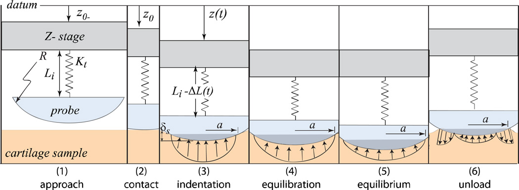
The six possible steps of the indentation test are illustrated in Fig. 2. To begin the test, the probe is manually positioned to within 15µm±10µm of the cartilage surface. The load cell signal is zeroed prior to actuation to eliminate bias from fluid surface tension. The probe is then actuated downward at a prescribed rate to a target depth. Contact occurs when the force measurement (an average) exceeds zero by three standard deviations of the signal noise (no detectable snap to contact). Following indentation the stage is retracted at the prescribed indentation rate; an equilibration step is used only when measuring equilibrium properties. A five minute hold between measurements was used and allowed complete recovery to within our detection limits.
Figure 2.
Illustration of the measurements. The stage position, z(t), and load cell deflections (to which force is proportional), ΔL(t), are measured directly with independent capacitive displacement sensors. Data are acquired at 10kHz and averaged over a 0.01s window by custom software. Non-equilibrium measurements are made during the indentation phase. The sample is left to equilibrate only when equilibrium measurements are to be made; otherwise, the probe is immediately unloaded at the same rate.
The effects of depth and contact radius on the non-equilibrium response were tested by indenting to target depths in the range 22–140µm at constant rate of 7.7 µm/s before equilibrating. The indents were made in order of increasing depth for the first four measurements in an effort to minimize the volume affected by prior indentation. The last two were swapped to determine the significance of the order effect. The effects of rate on the non-equilibrium response were tested by indenting to a target depth of 200µm at rates in the range 0.58–21 µm/s. The equilibration step, which increases the time in contact by orders of magnitude, is omitted here to mitigate the potential effect of consolidation on subsequent measurements (the additional equilibration step had no detectable effect as shown in the results).
2.3 Indentation Analysis
The localized nature of the contact motivates the use of Hertz’s contact theory (Hertz, 1881; Johnson, 1985) which provides the relationship between normal force (Fn), sphere radius (R), Young’s modulus (E), Poisson’s ratio (ν), and penetration depth (δs). We define the contact modulus (Ec) using Hertz theory as follows:
| Eq. 1 |
The definition of the contact modulus eliminates the need to characterize Poisson’s ratio and Young’s modulus independently. The curvature of the cartilage and the compliance of the probe are considered negligible, so R is the probe radius and Ec is the cartilage contact modulus. The contact radius, a, is equal to the square root of the product of penetration depth and probe radius per Hertz’s theory.
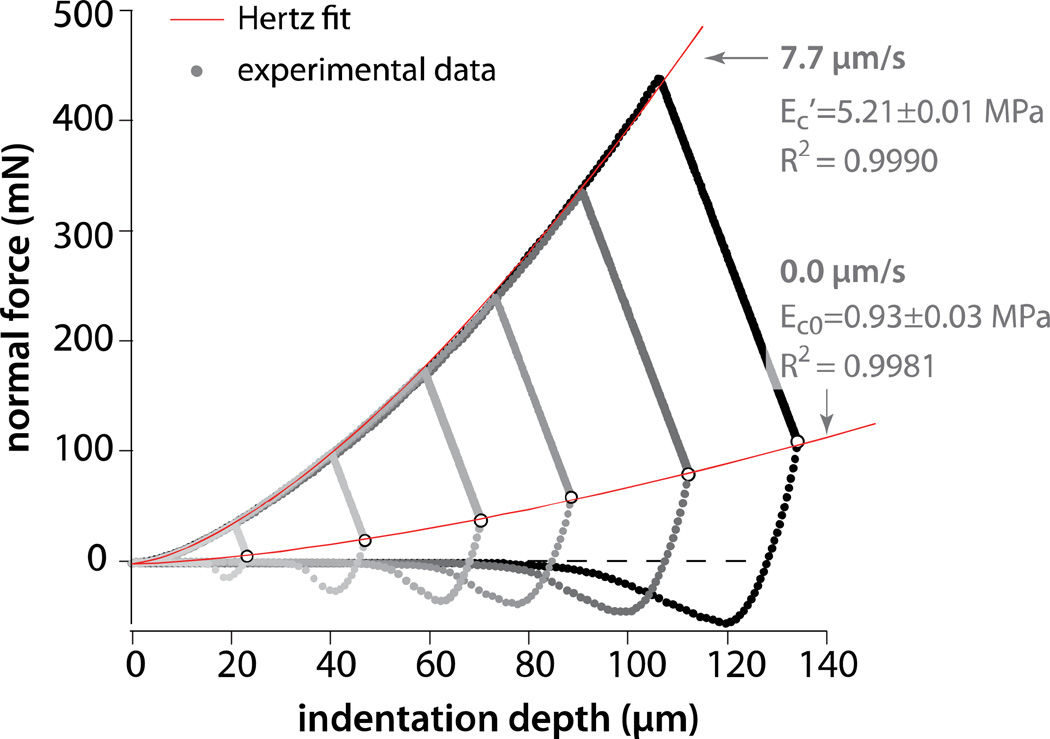
The equilibrium indentation response was constructed by indenting and equilibrating at six indentation depths. These equilibrium force and indentation depth data were then fit to Eq. 1 to obtain the equilibrium contact modulus, Ec0 (due to the matrix alone; see Fig. 3). Similarly, the force and indentation depth data were collected continuously during a single indentation at a prescribed rate were fit to Eq. 1 to obtain the effective contact modulus, Ec’.
Figure 3.
Results from variable-depth indentation and equilibration experiments with a 7.7 µm/s indentation rate, a 3.2 mm radius sphere, and PBS lubricant. The lines denote the least squares fits to the Hertz model. The equilibrium and effective contact moduli were Ec0=0.93±0.03 MPa and Ec’=5.21±0.01 MPa, respectively. The 95% confidence intervals are not visible behind the data labels.
The effective contact modulus characterizes the non-equilibrium response and comprises contributions from matrix stress and fluid pressure. The fluid load contribution, Fp, is the difference between the total force (F) and the force from the matrix (Fs). Per Eq. 1, the fluid load fraction, F’, can be expressed in terms of effective and equilibrium contact moduli.
| Eq. 2 |
2.4 Statistical Analysis
Measurement uncertainties were determined according to the ISO guide to the expression of uncertainties in measurement (ISO, 1993). Experimental force and indentation depth uncertainties were less than 1 mN and 1 µm, respectively.
The Monte Carlo method was used here to determine the contact modulus uncertainty for each (nonlinear least-squares) fit. (Sawyer and Burris, 2009). Briefly, 1,000 random samples from each force and depth measurement were generated (based on the reported statistics) to produce 1,000 random datasets. Each random dataset was fit individually to obtain 1,000 values of contact modulus. The mean and standard deviation were the nominal measurement and combined standard uncertainty, respectively. The law of propagation of uncertainty was used with Eq. 2 to analytically propagate these contact modulus uncertainties into the fluid load fraction.
3.0 Results
3.1 Effect of Indentation Depth on the Equilibrium Response
Six indentation measurements with target depths in the range 22–140 µm were used to study the equilibrium response. The equilibrium force (highlighted in white) increased with the depth to the 1.5 power as predicted by the Hertz model (Fig. 3). The fit produced an equilibrium contact modulus of 0.93 MPa with R2=0.9981 and a combined standard uncertainty of Uc(Ec0)=0.03MPa. The agreement with the model suggests that the underlying bone had no significant effect on the local mechanics of contact.
3.2 Effect of Indentation Depth and Contact Radius on the Non-Equilibrium Response
The same six measurements were used to determine the effect of depth on the non-equilibrium force response during indentation at a nominal rate of 7.7µm/s (Fig. 3). The indentations were repeatable and displayed no evidence of history dependence under the procedure described. The normal forces during indentation were approximately 5 times greater than the corresponding equilibrium forces. The best fit to the full (deepest curve) indentation yielded an effective contact modulus Ec’=5.21MPa, R2=0.9990, and Uc(Ec’)=0.01MPa. The non-equilibrium force response, which comprises contributions from matrix stress and fluid pressure, is also consistent with that of a Hertzian material.
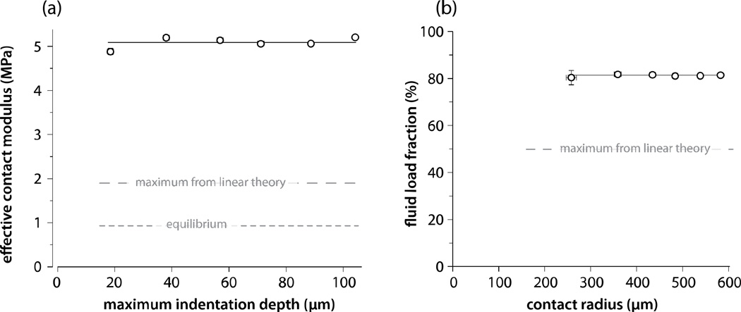
Each measurement was analyzed independently to study potential indentation depth and contact radius dependences. Although there is some evidence of a soft superficial region for the 20 µm indent, the indentation depth and contact radius had no statistically significant effect (Monte Carlo analysis revealed a mean slope of 1.7 kPa/µm ± 1.1 kPa/µm) on the effective contact modulus (Fig. 4a) or the fluid load fraction (Fig. 4b). Using linear poroelasticity theory, Agbezuge and Deresiewicz (1974) solved for the Hertzian contact response of interest here. The maximum possible effective contact modulus and fluid load fraction for a linear biphasic or poroelastic material is twice the equilibrium contact modulus and 50%, respectively. These measurements indicate that cartilage achieves substantially better load capacity and lubrication than a linear biphasic material (e.g. hydrogel).
Figure 4.
Effective contact modulus and fluid load fraction from indentation at 7.7 µm/s. Effective contact modulus (a) and fluid load fraction (b) did not vary significantly with indentation depth, contact radius or force during non-equilibrium indentation (depth, contact radius, and force are interdependent). The equilibrium contact modulus, Ec0, is shown for reference (a). Agbezuge and Deresiewicz, 1974, predicted the limiting Hertzian contact response for a linear poroelastic material (a, b).
3.2 Effect of Indentation Rate on the Non-Equilibrium Contact Modulus
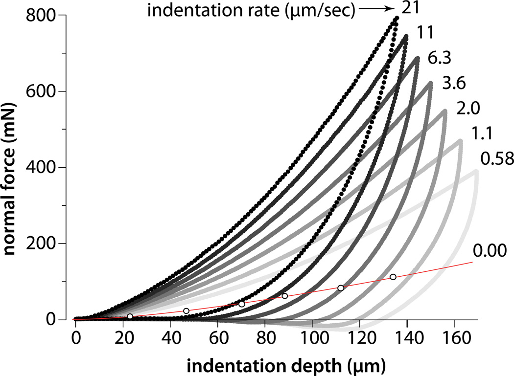
Normal force is plotted versus indentation depth (Fig. 5) for indentation rates varying from 0 to 21 µm/s. In every case, the force increased with depth to the 1.5 power (R2>0.998) in agreement with the Hertz model. The peak force systematically increased with increased speed and exceeded the equilibrium force at every depth. Elimination of the equilibration step significantly decreased total depth, time in contact, and pull-off force (by comparison to Fig. 3).
Figure 5.
Normal force response to depth for indentation rates from 0.58–21 µm/s. Equilibrium results are included for reference. The test consisted of indentation immediately followed by unloading at the same rate (i.e. the sample was not allowed to equilibrate as in Fig. 3).
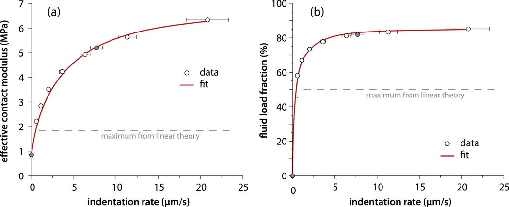
At 0.58 µm/s indentation rate, the effective contact modulus exceeds the poroelastic theoretical limit (Agbezuge and Deresiewics, 1974) of twice the equilibrium contact modulus (Fig. 6a). Fluid pressure supports 58% of the load (Fig. 6b) in this case. The effective contact modulus and fluid load fraction increased with indentation rate toward the asymptotes for infinite rate (instantaneous). At 21µm/s, the highest rate tested, fluid pressure supported 85% of the normal load.
Figure 6.
(a) Effective contact modulus and (b) fluid load fraction increase monotonically with indentation rate toward asymptotes representing the theoretical instantaneous response. The shaded data (7.7 µm/s) were collected from depth-dependent equilibrium and non-equilibrium measurements (Fig. 3); the others never equilibrated (Fig. 5). The consistency demonstrates insensitivity to the equilibration step. Effective and equilibrium moduli are used to determine the fluid load fraction (Eq. 2). The fits assume a model (described in the discussion) of the form and R is the probe radius. Eq. 2 relates Ec to F’. The best fits shown reflect a permeability k=6×10⁻⁴mm4/(Ns), and F’max=86.5%.
4.0 Discussion
The local equilibrium response of cartilage to contact by a spherical probe is well-fit by the Hertz model. This is in contrast to the macroscale responses of cartilage (Hayes et al., 1972) and other thin elastic foundations. The equilibrium contact modulus of the representative sample tested was 0.93 MPa; indentation at rates from 0.58–21 µm/s effectively increased the contact modulus by 2 to 6 times via 58%–85% interstitial fluid load support.
Theoretical studies of linear biphasic materials have shown that the maximum fluid load fractions are 33% (Armstrong et al., 1984) for unconfined compression and 50% (Agbezuge and Deresiewicz, 1974) for Hertzian contact. Significantly higher fluid load fractions are well-documented in practice. Cohen et al., (1998) showed that the high tensile stiffness of the collagen network effectively confines the tissue and dramatically increases the maximum fluid load fraction. Interfacial friction (Armstrong et al., 1984; Spilker and Suh, 1990) and the rigid bone substrate (Spilker and Suh, 1990; Ateshian and Wang, 1995) can have similar effects. These measurements shown no evidence of a substrate effect and Bonnevie et al. (2011) found µ≈0.03 during sliding at similar fluid load fractions. These observations suggest that a relatively large tensile to compressive modulus ratio (we will call this E*) was primarily responsible for the elevated fluid load fractions observed here.
Our results indicate that the fluid load fraction increases with deformation rate as expected, but is independent of contact radius from 250–600µm. These results, along with the Hertzian character of the non-equilibrium response can be understood through an analysis of the individual force contributors during Hertzian contact. Per Hertz’s theory, the elastic force contribution is: Fs = 4 · Ec0·a3 /(3 · R). Per Darcy’s Law, the pressure gradient along a streamline is the ratio of linear flow rate and permeability. Flow into a circular contact area with radius, a, produces a fluid pressure force component of the general form: Fp = B · δ̇ · a3 /k. The constant, B, is approximately 2/3 if lateral deformation is resisted, streamlines are semi-circular, and downward flow components are neglected to account for matrix consolidation. Therefore, the fluid load fraction becomes F' = Pe/(Pe + 2) where Pe = δ̇ · R/(Eco · k) (i.e. it is independent of force, indentation depth, and contact radius). Accordingly, the fluid load fraction approaches one as indentation rate increases. Cohen et al. (1998) showed that the actual asymptote, F’max, is less than 1 due to coupling of flow and deformation. With an asymptote of F’max, the fluid load fraction becomes:
| Eq. 3 |
Using this function to determine the best fits shown in Figure 6 yields F’max=86.5% and k=6×10⁻⁴ mm4/(Ns); the data qualitatively agree with the model and the permeability quantitatively agrees with Park et al. (2004) and Caligaris and Ateshian (2008).
The asymptote, F’max is an important functional parameter that depends on E*. Cohen et al. (1998) predict when ν=0 in unconfined compression (F’max=1/3 when E*=1). With the limit F’max=1/2 when E*=1 (Agbezuge and Deresiewicz, 1974) the Hertzian form becomes:
| Eq. 4 |
The Peclet number depends on probe radius rather than contact radius as is proposed by Ateshian (2009) for MCA. During sliding at a rate V, the pin traverses the contact radius, a, while the tissue is deformed by δs. Consequently, the deformation rate during sliding at V is: . Since a2 = R · δ (per Hertz), which is the same form predicted by Caligaris and Ateshian (note that Ec0=Ha when ν=0).
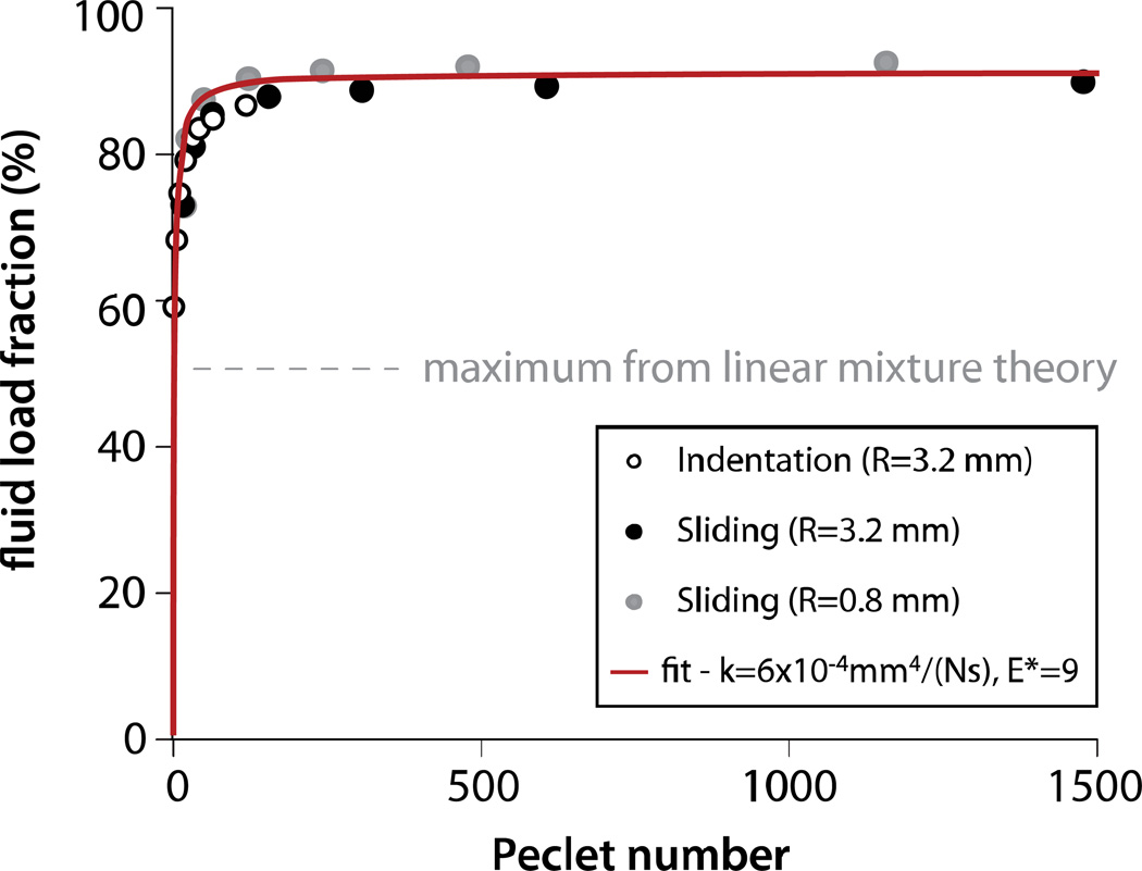
Equations 1 and 2 were used to determine fluid load fraction from the force and penetration depth data of Bonnevie et al. (2011) (note: we previously assumed only frontal contact which resulted in reported solid load fractions being halved). These results are plotted with the current indentation results in Figure 7 as functions of the appropriate Peclet number. There is striking agreement between the sliding response, the indentation response, and the model. This suggests that the pressure distribution during sliding is nearly axisymmetric as it is during indentation. The fit to the overall dataset indicates k=6×10⁻⁴mm4/(Ns) and E*=9. We found that E* tended to increase with Pe number (indentation alone is best fit with E*=6.4) which is consistent with the straightening of the collagen with increased stress in the toe region of the stress-strain curve (Mow et al., 2005). Figure 7 clearly illustrates the insensitivity of fluid load support to Pe≫1 (Ateshian, 2009). The results also suggest that although fluid load support decreases rapidly as Pe approaches one, it can be comparable to the theoretical maximum value of a linear biphasic material (33%) when Pe=1; we directly observed 58% fluid load support for Pe=3 here.
Figure 7.
Indentation and MCA sliding are analogous systems with comparable functional responses. The indentation results come from this study. The sliding data were determined using Equations 1 and 2 from the MCA results reported in Bonnevie et al. (2011). For indentation, ; this is equivalent to during MCA sliding. The fit to Eq. 3 yields k=6×10⁻⁴mm4/(Ns) and F’max=90% which indicates E*=9.
A primary aim of this work was to better understand the scale-dependent tribomechanics of cartilage. Consider the microscale results of Park et al. (2004) (R=2.5 µm, F=100 nN, V=0.1 mm/s), the local results of Bonnevie et al. (2011) (R=800 µm, F=45mN, V=1 mm/s), and the macroscale results of Caligaris and Ateshian (2008) (R=13mm, F=6.3N, V=1mm/s). Equations 1–4 can be used to determine contact radius, Peclet number, fluid load fraction and effective contact modulus with nothing more than experimental conditions and material properties. Assuming Ha =1 MPa, k=6×10⁻⁴mm4/(Ns), E*=9 gives contact radii of 600nm, 142µm, and 1.83mm, for the micro-, local, and macroscale studies mentioned above, respectively. Bonnevie et al. (2011) reported a measured contact radius of 140.4µm at these conditions. The corresponding Peclet numbers are 0.1, 237 and 3050; the corresponding fluid load fractions (also percent reductions in contact force, friction, and wear) are 4.7%, 89.4%, and 89.9%. The functionalities of micro- and macroscale contacts are very similar; this prediction is consistent with the friction results from these studies. This simple model (Eq. 3), motivated by the results of this indentation study, provides basic but important insights into the scale-dependent tribomechanics of cartilage.
This paper demonstrates a local regime with which the functional tissue properties (load support and lubrication) can be evaluated with local spatial resolution (~100 µm). The local properties will govern the local response and may play a critical role in determining where and under what conditions damage might be expected to occur. These local tribological contacts will be adopted for our future studies of location-specific functional properties, the effects of focal damage on cartilage properties, and the relationship between damage and properties during OA progression.
Supplementary Material
Acknowledgements
The authors gratefully acknowledge financial support from the NIH (grants P20-RR016458 and AR054385).
Footnotes
Publisher's Disclaimer: This is a PDF file of an unedited manuscript that has been accepted for publication. As a service to our customers we are providing this early version of the manuscript. The manuscript will undergo copyediting, typesetting, and review of the resulting proof before it is published in its final citable form. Please note that during the production process errors may be discovered which could affect the content, and all legal disclaimers that apply to the journal pertain.
Conflict of Interest Statement
The authors have no conflict of interest to report.
References
- Agbezuge LK, Deresiewicz H. Indentation of a Consolidating Half-Space. Israel Journal of Technology. 1974;12:322–338. [Google Scholar]
- Armstrong CG, Lai WM, Mow VC. An analysis of the unconfined compression of articular cartilage. J. Biomech. Eng. 1984;106:165–173. doi: 10.1115/1.3138475. [DOI] [PubMed] [Google Scholar]
- Ateshian GA. The role of interstitial fluid pressurization in articular cartilage lubrication. Journal of Biomechanics. 2009;42:1163–1176. doi: 10.1016/j.jbiomech.2009.04.040. [DOI] [PMC free article] [PubMed] [Google Scholar]
- Ateshian GA, Lai WM, Zhu WB, Mow VC. An Asymptotic Solution for the Contact of 2 Biphasic Cartilage Layers. Journal of Biomechanics. 1994;27:1347–1360. doi: 10.1016/0021-9290(94)90044-2. [DOI] [PubMed] [Google Scholar]
- Ateshian GA, Wang HQ. A Theoretical Solution for the Frictionless Rolling-Contact of Cylindrical Biphasic Articular-Cartilage Layers. Journal of Biomechanics. 1995;28:1341–1355. doi: 10.1016/0021-9290(95)00008-6. [DOI] [PubMed] [Google Scholar]
- Ateshian GA, Warden WH, Kim JJ, Grelsamer RP, Mow VC. Finite deformation biphasic material properties of bovine articular cartilage from confined compression experiments. J. Biomech. 1997;30:1157–1164. doi: 10.1016/s0021-9290(97)85606-0. [DOI] [PubMed] [Google Scholar]
- Athanasiou KA, Rosenwasser MP, Buckwalter JA, Malinin TI, Mow VC. Interspecies comparisons of in situ mechanical properties of distal femoral cartilage. J. Orthop. Res. 1991;9:330–340. doi: 10.1002/jor.1100090304. [DOI] [PubMed] [Google Scholar]
- Bendele AM. Animal models of osteoarthritis. J Musculoskel Neuron Interact. 2001;4:363–376. [PubMed] [Google Scholar]
- Bonnevie ED, Baro VJ, Wang LY, Burris DL. In Situ Studies of Cartilage Microtribology: Roles of Speed and Contact Area. Tribology Letters. 2011;41:83–95. doi: 10.1007/s11249-010-9687-0. [DOI] [PMC free article] [PubMed] [Google Scholar]
- Brand RA. Joint Contact Stress: A Reasonable Surrogate for Biological Processes? Iowa Orthop. J. 2005;25:82–94. [PMC free article] [PubMed] [Google Scholar]
- Burris DL, Sawyer WG. Addressing Practical Challenges of Low Friction Coefficient Measurements. Tribology Letters. 2009;35:17–23. [Google Scholar]
- Caligaris M, Ateshian GA. Effects of sustained interstitial fluid pressurization under migrating contact area, and boundary lubrication by synovial fluid, on cartilage friction. Osteoarthritis and Cartilage. 2008;16:1220–1227. doi: 10.1016/j.joca.2008.02.020. [DOI] [PMC free article] [PubMed] [Google Scholar]
- Cohen B, Lai WM, Mow VC. A transversely isotropic biphasic model for unconfined compression of growth plate and chondroepiphysis. J. Biomech. Eng. 1998;120:491–496. doi: 10.1115/1.2798019. [DOI] [PubMed] [Google Scholar]
- Forster H, Fisher J. The influence of loading time and lubricant on the friction of articular cartilage. Proceedings of the Institution of Mechanical Engineers Part H-Journal of Engineering in Medicine. 1996;210:109–119. doi: 10.1243/PIME_PROC_1996_210_399_02. [DOI] [PubMed] [Google Scholar]
- Fukubayashi T, Hisashi K. The contact area and pressure distribution pattern of the knee. Acta orthop. scand. 1980;51:871–879. doi: 10.3109/17453678008990887. [DOI] [PubMed] [Google Scholar]
- Hayes WC, Herrmann G, Mockros LF, Keer LM. Mathematical-Analysis for Indentation Tests of Articular-Cartilage. Journal of Biomechanics. 1972;5 doi: 10.1016/0021-9290(72)90010-3. 541-&. [DOI] [PubMed] [Google Scholar]
- Hertz H. On the contact of Elastic Solids. Journal für die reine und angewandte Mathematik. 1881 [Google Scholar]
- ISO. Guide to the Expression of Uncertainty in Measurement (Corrected and Reprinted in 1995) 1993. [Google Scholar]
- Johnson KL. Contact Mechanics. UK: Cambridge University Press; 1985. [Google Scholar]
- Krishnan R, Kopacz M, Ateshian GA. Experimental verification of the role of interstial fluid prezzurization in cartilage lubrication. Journal of Orthopaedic Research. 2004;22:565–570. doi: 10.1016/j.orthres.2003.07.002. [DOI] [PMC free article] [PubMed] [Google Scholar]
- Mak AF, Lai WM, Mow VC. Biphasic indentation of articular cartilage- theoretical analysis. J. Biomech. 1987;20:703–714. doi: 10.1016/0021-9290(87)90036-4. [DOI] [PubMed] [Google Scholar]
- McCutchen CW. The frictional properties of animal joints. Wear. 1962;5:1–17. [Google Scholar]
- McCutchen CW. Lubrication of Joints, the joints and synovial fluid. New York: Academic Press; 1978. [Google Scholar]
- Mow VC, Kuei SC, Lai WM, Armstrong CG. Biphasic Creep and Stress-Relaxation of Articular-Cartilage in Compression - Theory and Experiments. Journal of Biomechanical Engineering-Transactions of the Asme. 1980;102:73–84. doi: 10.1115/1.3138202. [DOI] [PubMed] [Google Scholar]
- Mow VC, Gu WY, Chen FH. Structure and Function of Articular Cartilage, Basic Orthopedic Biomechanics and Mechanobiology. Lipponcott Williams and Wilkins. 2005:181–258. [Google Scholar]
- Murphy L, Schwartz TA, Helmick CG, Renner JB, Tudor G, Koch G, Dragomir A, Kalsbeek WD, Luta G, Jordan JM. Lifetime risk of symptomatic knee osteoarthritis. Arthritis & Rheumatism-Arthritis Care & Research. 2008;59:1207–1213. doi: 10.1002/art.24021. [DOI] [PMC free article] [PubMed] [Google Scholar]
- Park S, Costa KD, Ateshian GA. Microscale frictional response of bovine articular cartilage from atomic force microscopy. Journal of Biomechanics. 2004;37:1679–1687. doi: 10.1016/j.jbiomech.2004.02.017. [DOI] [PMC free article] [PubMed] [Google Scholar]
- Park SH, Krishnan R, Nicoll SB, Ateshian GA. Cartilage interstitial fluid load support in unconfined compression. Journal of Biomechanics. 2003;36:1785–1796. doi: 10.1016/s0021-9290(03)00231-8. [DOI] [PMC free article] [PubMed] [Google Scholar]
- Sawyer WG, Burris DL. Measurement Uncertainties in Wear Rates. Tribology Letters. 2009;36:81–87. [Google Scholar]
- Setton LA, Mow VC, Muller FJ, Pita JC, Howell DS. Mechanical-Properties of Canine Articular-Cartilage Are Significantly Altered Following Transection of the Anterior Cruciate Ligament. Journal of Orthopaedic Research. 1994;12:451–463. doi: 10.1002/jor.1100120402. [DOI] [PubMed] [Google Scholar]
- Spilker RL, Suh J. Effects of friction on the unconfined compressive response of articular cartilage finite element analysis. J. Biomech. Eng. 1990;112:138–146. doi: 10.1115/1.2891164. [DOI] [PubMed] [Google Scholar]
- Spilker RL, Suh JK, Mow VC. A Finite-Element Analysis of the Indentation Stress-Relaxation Response of Linear Biphasic Articular-Cartilage. Journal of Biomechanical Engineering-Transactions of the Asme. 1992;114:191–201. doi: 10.1115/1.2891371. [DOI] [PubMed] [Google Scholar]
Associated Data
This section collects any data citations, data availability statements, or supplementary materials included in this article.


