Abstract
Although nanoparticles with exquisite properties have been synthesized for a variety of applications, their incorporation into functional devices is challenging owing to the difficulty in positioning them at specified sites on surfaces. In contrast with the conventional synthesis-then-assembly paradigm, scanning probe block copolymer lithography can pattern precursor materials embedded in a polymer matrix and synthesize desired nanoparticles on site, offering great promise for incorporating nanoparticles into devices. This technique, however, is extremely limited from a materials standpoint. To develop a materials-general method for synthesizing nanoparticles on surfaces for broader applications, a mechanistic understanding of polymer-mediated nanoparticle formation is crucial. Here, we design a four-step synthetic process that enables independent study of the two most critical steps for synthesizing single nanoparticles on surfaces: phase separation of precursors and particle formation. Using this process, we elucidate the importance of the polymer matrix in the diffusion of metal precursors to form a single nanoparticle and the three pathways that the precursors undergo to form nanoparticles. Based on this mechanistic understanding, the synthetic process is generalized to create metal (Au, Ag, Pt, and Pd), metal oxide (Fe2O3, Co2O3, NiO, and CuO), and alloy (AuAg) nanoparticles. This mechanistic understanding and resulting process represent a major advance in scanning probe lithography as a tool to generate patterns of tailored nanoparticles for integration with solid-state devices.
The integration of nanoparticles into devices has enabled applications spanning sensing (1, 2), catalysis (3), electronics (2), photonics (4), and plasmonics (5, 6), but synthesizing individual nanoparticles with control over size, composition, and placement on substrates is challenging (1–3, 6, 7). With conventional approaches, nanoparticles are synthesized and subsequently positioned on a surface using techniques such as parallel printing (8), surface dewetting (9, 10), microdroplet molding (7), nanoparticle sliding (11), direct writing (4, 12, 13), and self-assembly (2, 14, 15). However, it is difficult and in most cases, impossible to use these methods to reliably make and position a single particle on a surface with nanometer-scale control.
In contrast with the conventional synthesis-then-positioning paradigm, which is the basis for most single-particle device incorporation schemes, scanning probe block copolymer lithography (SPBCL) is an example of precursor positioning-then-synthesis. The technique uses concepts from the block copolymer community (16) and the positional control offered by dip-pen nanolithography (DPN) (17) to deliver attoliter volumes of a metal-coordinated block copolymer onto a surface, which then can be used to synthesize individual nanoparticles (18, 19). Importantly, SPBCL allows one to directly synthesize arbitrary patterns of single nanoparticles over large areas on a surface, which has been useful for immobilizing single proteins (20) and studying nanoparticle coalescence in situ (21). Thus far, the technique has been extensively used to synthesize Au nanoparticles, and there is one example of cadmium sulfide nanoparticle synthesis (18, 19); however, when other metals and oxides are targeted, either they typically do not form or the technique results in multiple nanoparticles per feature. One hypothesis for this observation pertains to the high mobility of gold compared with many other materials (22), which creates a barrier to getting them to coalesce into single particles under the conditions typically used to make Au nanoparticles. If the use of this technique is to be expanded, a mechanistic understanding of the nanoparticle formation process is crucial.
Here, we present a study of the two most critical steps for synthesizing single nanoparticles on a surface by SPBCL, precursor phase separation and nanoparticle formation, and from this study, we develop a mechanism for particle formation, which leads to an approach for synthesizing individual nanoparticles with control over size, composition, and surface placement. Specifically, this technique is materials-general, and it allows one to synthesize a diverse class of nanoparticles, including nanoparticles composed of Au, Ag, Pt, Pd, Fe2O3, Co2O3, NiO, CuO and alloys of Au and Ag.
Results and Discussion
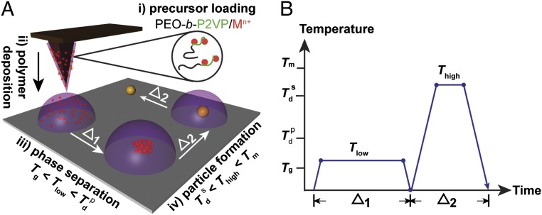
With the original SPBCL process (18), the patterned polymer features are directly subjected to oxygen plasma to reduce the embedded metal ions. To test our hypothesis, that to form an individual particle per feature, aggregation of the metal ions within the polymer is required before metal ion reduction and particle nucleation, we began to explore parameters that separated our proposed key events in particle synthesis (Fig. 1). Specifically, we studied how thermal annealing could be used instead of oxygen plasma to facilitate and separate metal ion aggregation from reduction. With this synthetic procedure, the metal ion precursor is loaded within the polymer, the polymer is deposited from atomic force microscope (AFM) tips by DPN, and the patterned nanoreactors are annealed at a low temperature to initiate phase separation and then subsequently, at a higher temperature to facilitate metal ion reduction, particle formation, and polymer decompo-sition. The multifunctional block copolymer sequentially acts as a transport vehicle for precursor deposition, a diffusion media for metal precursor aggregation, a reducing agent for precursor reduction, and a spatially confined nanoreactor for particle synthetic reactions. In contrast to applications in microelectronics, where the diffusion and aggregation of metal and metal ions within polymers are detrimental (23, 24), this method uses polymer-mediated metal diffusion as an advantage.
Fig. 1.
Schematic of polymer-mediated on-site synthesis of nanoparticles. (A) The method consists of four steps: precursor loading, polymer deposition, precursor phase separation, and particle formation. Metal ions, Mn+, are (i) loaded onto PEO-b-P2VP, (ii) cast onto dip-pens, and deposited onto a substrate. (iii) The substrate is then thermally annealed at Tlow to allow the segregation of metal ions inside the polymer nanoreactor. (iv) A chemical reaction is conducted within the polymer nanoreactor to synthesize a nanoparticle by annealing at Thigh. At the end of the synthesis, the block copolymers are decomposed. (B) Heating profile of the annealing process. The two heating cycles (Δ1 and Δ2) correspond to the cycles at Tlow and Thigh in A. The two annealing temperatures, Tlow and Thigh, are between Tg and  and between
  and Tm, respectively.
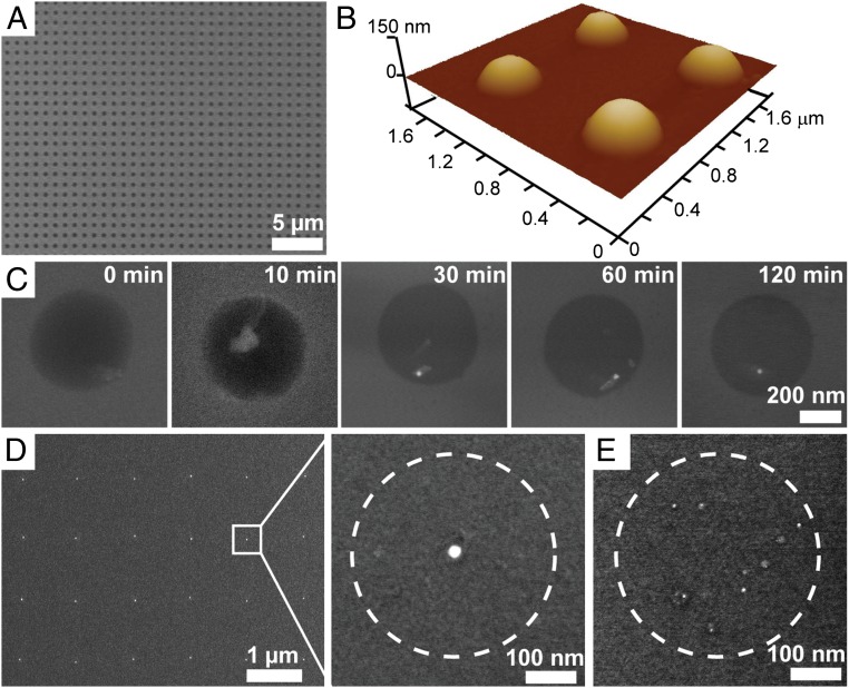
In a typical experiment, metal precursors are mixed with an aqueous solution of the block copolymer poly(ethylene oxide)-block-poly(2-vinyl pyridine) (PEO-b-P2VP) and then cast onto arrays of DPN tips. The tips are mounted onto an AFM and subsequently brought into contact with hydrophobic surfaces to deposit the block copolymer loaded with metal precursors at selected sites, yielding large arrays of uniform domed features that serve as nanoreactors for nanoparticle synthesis in later steps (Fig. 2 A and B). After patterning, the metal precursors are homogenously distributed in the polymer nanoreactors, which is evidenced by uniform contrast as viewed by scanning EM (SEM). To effect metal ion aggregation without reduction, the substrate with the nanoreactors was heated to Tlow = 150 °C in a tube furnace under a flow of Ar. This temperature is above the glass transition temperature of the two blocks of the block copolymer (Tg = −76 °C and 78 °C for PEO and P2VP, respectively; Polymer Source) but below the decomposition temperature of the block copolymer ( = 409 °C) (Fig. S1). We adopted this strategy, because it is known in the microelectronics packaging field that metal ions will diffuse within polymers under such circumstances (22–24). In certain cases (Au or Ag), continued heating at 150 °C results in metal ion reduction and formation of a nanoparticle. In all other cases studied, after aggregation of the precursor at Tlow, a high temperature annealing step at Thigh = 500 °C is performed to decompose the polymer matrix and form the nanoparticle. By annealing at a temperature Thigh that is above the thermal decomposition temperature
  of the metal salt precursor but below the melting temperature Tm of the metal, the precursor decomposes and forms metal nanoparticles. Phase separation during the previous step concentrates the precursors into a single region, enabling the formation of a single nanoparticle in each spot (Fig. 2D). This process also decomposes the polymer, thereby removing the majority of the organic material.
Fig. 2.
Probing the mechanism of particle formation using AFM and SEM. (A) Large-area patterned nanoreactors loaded with gold precursors on a hydrophobic silicon substrate. (B) Example AFM image of a patterned array of nanoreactors, the diameters of which are 400 nm. (C) Ex situ SEM images that illustrate the diffusion and aggregation of gold precursors inside the polymer matrix. The images are taken from different polymer nanoreactors. (D) Typical array of as-synthesized gold nanoparticles on a hydrophobic silicon substrate and a magnified view of a single gold nanoparticle. (E) Effect of thermal annealing on the synthesis of single nanoparticles. Multiple gold nanoparticles are synthesized if annealing at Tlow is omitted. Dashed circles denote the original size of the nanoreactor.
The particle formation process was investigated by ex situ SEM, which allows one to monitor the polymer nanoreactors at various time points during annealing (Fig. 2C). As the Au precursor phase-separates inside the polymer matrix and forms an aggregate, the even contrast that is attributed to a homogeneous metal ion distribution transitions to a more heterogeneous appearance with one bright area, which is attributed to a localized high concentration of metal ions (Fig. 2C, 10 min). Because PEO is a weak reducing agent (25) (Fig. S2 shows that PEO can slowly reduce HAuCl4 under ambient conditions), additional annealing at Tlow was observed to reduce the Au precursor and form an Au seed. Eventually, the Au precursor is fully reduced, and a single gold nanoparticle is formed inside each polymer nanoreactor.
For the particles that form by reduction of the precursor material, the process by which a given precursor forms a nanoparticle is either direct reduction by the polymer or through its thermal decomposition (see below for details) depending on the reduction potential of the metal precursors (Table S1), but the annealing protocol remains the same regardless of the pathway. It is important to emphasize that, if the Tlow annealing step is omitted and the samples are directly annealed at Thigh, multiple nanoparticles per polymer feature are observed (Fig. 2E). This observation is explained by the fact that the nanoreactors decompose too rapidly, leaving the metal precursors unable to diffuse across the surface to form a single nanoparticle.
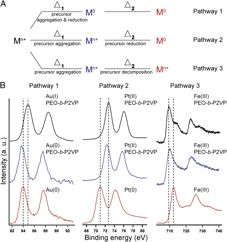
X-ray photoelectron spectroscopy (XPS) shows that this synthetic process can be used to form nanoparticles from many different metal precursors through one of three different reaction pathways (Fig. 3A). Depending on the reduction potential of the precursor, the metal in the final nanoparticle can be reduced by PEO when annealed at Tlow (pathway 1), be thermally reduced during annealing at Thigh (pathway 2), or end up in the same oxidation state as the precursor (pathway 3). The XPS data support the formation of Au particles through pathway 1 (Fig. 3B, Left). The Au 4f7/2 peak for the salt precursor ink is at 84.9 eV, which is within the expected range for AuI; this partial reduction could be attributed to either reduction by PEO or photoreduction during the measurement (26). After thermal annealing at Tlow, the Au 4f7/2 peak shifts to 83.8 eV, indicating that the Au precursor has been reduced further by PEO (25). The peak is slightly lower in energy than expected for bulk gold (84.0 eV). We attribute this finding to the presence of electron-donating PEO on the Au surface, which is a known effect for Au nanoparticles suspended in electron-donating surface ligands (27). After thermal decomposition at Thigh, the positions of the Au 4f peaks shift slightly higher in energy to match the peak positions of bulk Au. Metals with slightly lower reduction potentials, such as Pt and Pd, follow reduction pathway 2 (Fig. 3B, Center). In the case of Pt, for both the fresh ink and after annealing at Tlow, the Pt 4f7/2 peak is in the range for PtII, which we again attribute to either reduction by PEO or in situ photoreduction. XPS reveals that the PtII has been fully reduced to Pt0 after thermal annealing at Thigh, indicated by the shift in energy of the Pt 4f7/2 peak to 70.9 eV, which closely matches the binding energy of metallic Pt. This pathway was also corroborated by ex situ transmission EM (TEM) (Fig. S3). Finally, metals with a much lower reduction potential, such as Fe, follow pathway 3 (Fig. 3B, Right). The XPS spectra for both the fresh ink and after annealing at Tlow showed that the Fe 2p3/2 peak was ∼709–710 eV, which is consistent with mixed oxides of Fe (28). At the end of the annealing processes, the Fe 2p3/2 peak shifted in energy to 712.3 eV, which we attribute to the formation of Fe2O3, an assignment also made by others (28) and confirmed by high-resolution TEM (HRTEM) (Fig. 4).
Fig. 3.
Probing the nanoparticle synthetic pathways using XPS. (A) Schematic of the three pathways for polymer-mediated nanoparticle formation on surfaces. Mn+ and M0 denote metal ions and fully reduced metal, respectively. Δ1 and Δ2 correspond to the two heating cycles at Tlow and Thigh, respectively. (B) The spectra are collected before annealing (black), after annealing at Tlow (blue), and after annealing at Thigh (red) for Au (Left), Pt (Center), and Fe (Right). All spectra are shifted vertically for clarity. Dashed lines denote the initial and final peak positions.
Fig. 4.
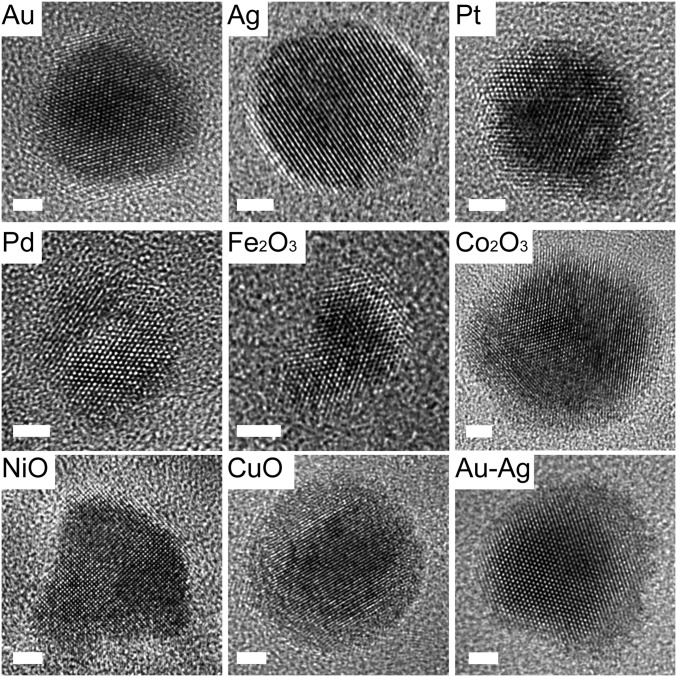
Generalization of nanoparticle synthesis. HRTEM images show the crystallinity of the nanoparticles. (Scale bars: 2 nm.)
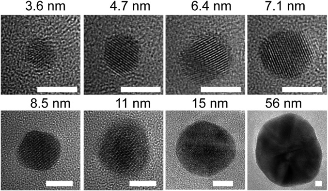
Based on the proposed pathways for polymer-mediated diffusion and reduction of the metal precursors, we devised a general method for synthesizing nanoparticles composed of eight transition metals. All of the precursor materials considered follow one of the three aforementioned particle formation pathways (Fig. 3, Fig. S4, and Table S2). For example, Ag, like Au, forms particles through pathway 1 (Fig. S5). These types of particles are some of the easiest to make by this method, because their precursors can be reduced easily and migrate even after reduction at Tlow. Pd nanoparticles, like Pt, form through pathway 2, because Pd is not very highly mobile in the reduced state, and therefore, ion aggregation must occur before reduction to avoid the generation of multiple nucleation sites and many particles within one polymer feature. Co, Ni, and Cu, like Fe, form oxide nanoparticles through pathway 3. The precursors must aggregate before annealing at Thigh, which facilitates oxide formation and polymer decomposition. The crystallinity and composition of the synthesized nanoparticles were verified by HRTEM (Fig. 4) in addition to energy dispersive X-ray spectroscopy (EDS) (Fig. S6) and XPS (Fig. S7). It is important to note here that many of the particles formed through pathway 3 exist as metal oxides under ambient conditions, and in principle, they could be annealed under a reducing atmosphere to obtain metal nanoparticles (29). Furthermore, metal alloy nanoparticles (for instance, of Au and Ag) can also be synthesized by simply blending the metal precursors in the ink, showing the versatility of the method (Fig. 4). In these examples, 1:1 alloys were formed by loading the Ag+ and Au3+ precursors together in the polymer. Finally, by changing the amount of metal precursors loaded on the block copolymer and the size of the patterned nanoreactors, the nanoparticle size was varied from 3.6 to 56 nm (Fig. 5). As shown previously (18), for a given ratio of metal precursors to block copolymer, the polymer feature size can be used to tune the size of the final nanoparticle, resulting in a very low polydispersity (∼4%) across a broad range of nanoparticle sizes. In the present work, we tune both the ratio of metal precursor to block copolymer and the polymer feature size to control the final nanoparticle size. No significant variation in nanoparticle size between batches was observed.
Fig. 5.
HRTEM images of gold nanoparticles of controlled size. (Scale bars: 5 nm.)
The insights garnered from these studies provide a rational way of understanding polymer-mediated particle formation on surfaces. Specifically, all structures to date follow one of three pathways, allowing one to access a wide variety of nanoparticle compositions, including metals, metal oxides, and alloys. Moreover, in principle, because the technique allows one to control nanoparticle placement, it will allow researchers to integrate as-synthesized nanoparticles directly into functional single-particle devices. In addition, the ability to synthesize homogenous or combinatorial arrays of nanoparticles on surfaces with control over individual particle composition and size will enable important fundamental studies and technological applications in fields spanning catalysis, nanomagnetism, microelectronics, and plasmonics. Finally, the pathway-dependent observations pertaining to these polymer nanoreactors likely will extend to other block copolymer-mediated particle syntheses, including ones that target 2D- and 3D-latticed structures (30–32).
Materials and Methods
Materials.
Block copolymer PEO-b-P2VP (Mn = 2.8-b-1.5 kg⋅mol−1, polydispersity index = 1.11) was purchased from Polymer Source and used as received. The glass transition temperatures Tg for PEO and P2VP of the block copolymer are −76 °C and 78 °C, respectively (Polymer Source). Metal compounds, HAuCl4⋅3H2O, AgNO3, H2PtCl6⋅6H2O, Na2PdCl4, Fe(NO3)3⋅9H2O, Co(NO3)2⋅6H2O, Ni(NO3)2⋅6H2O, and Cu(NO3)2⋅3H2O, were purchased from Sigma-Aldrich. HCl and HNO3 were purchased from Sigma-Aldrich and diluted before use. Hexamethyldisilazane (HMDS) and hexane were purchased from Sigma-Aldrich and used as received. DPN pen arrays (type M, no gold coating) were purchased from Nanoink, Inc. Hydrophobic silicon nitride membranes (membrane thickness = 15 or 50 nm) were purchased from Ted Pella, Inc. Silicon wafers were purchased from Nova Electronic Materials.
Sample Preparation.
PEO-b-P2VP and metal compounds were dissolved in deionized water. After blending the solutions of polymer and metal compound, the pH of the solution was controlled to be between 3 and 4 by adding HCl or HNO3 for Cl−- or NO3−- containing metal compounds, respectively (Fig. S8). The final ink had a PEO-b-P2VP concentration of 5–100 mg⋅mL−1. The ratio of 2-vinylpyridine:Mn+ was varied between 2:1 and 256:1 to control the size of the nanoparticles. After stirring overnight, the solution was used to dip-coat the DPN pen array. After drying in an N2 stream, the pen array was brought in contact with a substrate to generate arbitrary arrangements of nanoreactors using an NScriptor (NanoInk, Inc.) in a chamber with controlled humidity. The relative humidity was held in the range of 75–95% to control the dimensions of polymer nanoreactors delivered from the pen array to the substrate. Both hydrophobic silicon nitride membranes and silicon wafers treated with HMDS were used. Si wafers were kept in a desiccator with two vials of HMDS and hexane mixture for 24 h to ensure their hydrophobicity.
After patterning, the substrate was loaded into a tube furnace and annealed in an Ar stream. The annealing conditions were programmed as follows: ramp to 150 °C in 1 h, soak at 150 °C for 4–24 h, cool down to room temperature in 1 h, ramp to 500 °C in 1 h, soak at 500 °C for 2–4 h, and cool down to room temperature in 1 h. The soaking time was varied to ensure full phase separation between the metal compound and the polymer at 150 °C and full decomposition of all materials at 500 °C.
AFM.
AFM measurements were performed using a Dimension Icon (Bruker) to obtain 3D profiles of the patterned nanoreactors.
SEM and Energy-Dispersive X-Ray Spectroscopy.
Samples prepared on hydrophobic silicon wafers were imaged with a Hitachi S-4800 SEM at an acceleration voltage of 5 kV and a current of 20 μA. Probe current was set to high, and focus mode was set to ultrahigh resolution. Only the upper second electron detector was used. To determine the elemental composition, INCA (INCA 4.15; Oxford Instruments) was used to obtain energy-dispersive X-ray spectroscopy (EDX) spectra.
Scanning TEM, HRTEM, and EDX.
After annealing, samples prepared on 50-nm-thick silicon nitride membranes were imaged with a Hitachi scanning TEM HD-2300A in Z-contrast mode at an acceleration voltage of 200 kV and a current of 78 μA. EDX spectra were obtained with Thermo Scientific NSS 2.3. Samples prepared on 15-nm-thick silicon nitride membranes were imaged with a JEOL 2100F at an acceleration voltage of 200 kV.
Thermogravimetric Analysis.
The polymer decomposition temperature was measured on a thermogravimetric analysis/differential scanning calorimetry (DSC) (Mettler Toledo) by heating from room temperature to 600 °C at a ramping rate of 10 °C/min. The measurement was performed under an N2 atmosphere.
XPS.
To monitor the reduction of metal compounds, aqueous solutions of PEO-b-P2VP with the corresponding metal compound were drop-cast on Si wafers. After annealing at 150 °C and 500 °C (the same procedure as patterned samples), the samples were loaded into a vacuum chamber for XPS measurement [electron spectroscopy for chemical analysis (ESCA) probe; Omicron].
Supplementary Material
Acknowledgments
The authors thank the Northwestern University Electron Probe Instrumentation Center (EPIC). D.J.E. acknowledges the Department of Defense for an National Defense Science and Engineering Graduate fellowship. K.A.B. acknowledges support from Northwestern University’s International Institute for Nanotechnology. C.A.M. acknowledges the US Air Force Office of Scientific Research (AFOSR), the Defense Advanced Research Projects Agency (DARPA), the National Science Foundation (NSEC program), and UOP-Honeywell for support of this research.
Footnotes
The authors declare no conflict of interest.
This article contains supporting information online at www.pnas.org/lookup/suppl/doi:10.1073/pnas.1220689110/-/DCSupplemental.
References
- 1.Liu N, Tang ML, Hentschel M, Giessen H, Alivisatos AP. Nanoantenna-enhanced gas sensing in a single tailored nanofocus. Nat Mater. 2011;10(8):631–636. doi: 10.1038/nmat3029. [DOI] [PubMed] [Google Scholar]
- 2.Shipway AN, Katz E, Willner I. Nanoparticle arrays on surfaces for electronic, optical, and sensor applications. Chem Phys Chem. 2000;1(1):18–52. doi: 10.1002/1439-7641(20000804)1:1<18::AID-CPHC18>3.0.CO;2-L. [DOI] [PubMed] [Google Scholar]
- 3.Kraus T, et al. Nanoparticle printing with single-particle resolution. Nat Nanotechnol. 2007;2(9):570–576. doi: 10.1038/nnano.2007.262. [DOI] [PubMed] [Google Scholar]
- 4.Huang L, et al. Matrix-assisted dip-pen nanolithography and polymer pen lithography. Small. 2010;6(10):1077–1081. doi: 10.1002/smll.200901198. [DOI] [PMC free article] [PubMed] [Google Scholar]
- 5.Rycenga M, et al. Controlling the synthesis and assembly of silver nanostructures for plasmonic applications. Chem Rev. 2011;111(6):3669–3712. doi: 10.1021/cr100275d. [DOI] [PMC free article] [PubMed] [Google Scholar]
- 6.Nelayah J, et al. Mapping surface plasmons on a single metallic nanoparticle. Nat Phys. 2007;3(5):348–353. [Google Scholar]
- 7.Cheng W, Park N, Walter MT, Hartman MR, Luo D. Nanopatterning self-assembled nanoparticle superlattices by moulding microdroplets. Nat Nanotechnol. 2008;3(11):682–690. doi: 10.1038/nnano.2008.279. [DOI] [PubMed] [Google Scholar]
- 8.Kim H, et al. Parallel patterning of nanoparticles via electrodynamic focusing of charged aerosols. Nat Nanotechnol. 2006;1(2):117–121. doi: 10.1038/nnano.2006.94. [DOI] [PubMed] [Google Scholar]
- 9.Huang J, Kim F, Tao AR, Connor S, Yang P. Spontaneous formation of nanoparticle stripe patterns through dewetting. Nat Mater. 2005;4(12):896–900. doi: 10.1038/nmat1517. [DOI] [PubMed] [Google Scholar]
- 10.Martin CP, et al. Controlling pattern formation in nanoparticle assemblies via directed solvent dewetting. Phys Rev Lett. 2007;99(11):116103. doi: 10.1103/PhysRevLett.99.116103. [DOI] [PubMed] [Google Scholar]
- 11.Dietzel D, et al. Frictional duality observed during nanoparticle sliding. Phys Rev Lett. 2008;101(12):125505. doi: 10.1103/PhysRevLett.101.125505. [DOI] [PubMed] [Google Scholar]
- 12.Hung S-C, et al. Dip pen nanolithography of conductive silver traces. J Phys Chem C. 2010;114(21):9672–9677. [Google Scholar]
- 13.Wang WM, Stoltenberg RM, Liu S, Bao Z. Direct patterning of gold nanoparticles using dip-pen nanolithography. ACS Nano. 2008;2(10):2135–2142. doi: 10.1021/nn8005416. [DOI] [PubMed] [Google Scholar]
- 14.Barsotti RJ, Jr, et al. Assembly of metal nanoparticles into nanogaps. Small. 2007;3(3):488–499. doi: 10.1002/smll.200600334. [DOI] [PubMed] [Google Scholar]
- 15.Shevchenko EV, Talapin DV, Kotov NA, O’Brien S, Murray CB. Structural diversity in binary nanoparticle superlattices. Nature. 2006;439(7072):55–59. doi: 10.1038/nature04414. [DOI] [PubMed] [Google Scholar]
- 16.Bates FS, Fredrickson GH. Block copolymers–designer soft materials. Phys Today. 1999;52(2):32–38. [Google Scholar]
- 17.Piner RD, Zhu J, Xu F, Hong SH, Mirkin CA. “Dip-Pen” nanolithography. Science. 1999;283(5402):661–663. doi: 10.1126/science.283.5402.661. [DOI] [PubMed] [Google Scholar]
- 18.Chai J, et al. Scanning probe block copolymer lithography. Proc Natl Acad Sci USA. 2010;107(47):20202–20206. doi: 10.1073/pnas.1014892107. [DOI] [PMC free article] [PubMed] [Google Scholar]
- 19.Giam LR, et al. Positionally defined, binary semiconductor nanoparticles synthesized by scanning probe block copolymer lithography. Nano Lett. 2012;12(2):1022–1025. doi: 10.1021/nl204233r. [DOI] [PubMed] [Google Scholar]
- 20.Chai J, Wong LS, Giam L, Mirkin CA. Single-molecule protein arrays enabled by scanning probe block copolymer lithography. Proc Natl Acad Sci USA. 2011;108(49):19521–19525. doi: 10.1073/pnas.1116099108. [DOI] [PMC free article] [PubMed] [Google Scholar]
- 21.Chai J, Liao X, Giam LR, Mirkin CA. Nanoreactors for studying single nanoparticle coarsening. J Am Chem Soc. 2012;134(1):158–161. doi: 10.1021/ja2097964. [DOI] [PubMed] [Google Scholar]
- 22.Javey A, Dai H. Regular arrays of 2 nm metal nanoparticles for deterministic synthesis of nanomaterials. J Am Chem Soc. 2005;127(34):11942–11943. doi: 10.1021/ja0536668. [DOI] [PubMed] [Google Scholar]
- 23.Kiene M, Strunskus T, Peter R, Faupel F. Evidence of aggregation-induced copper immobilization during polyimide metallization. Adv Mater. 1998;10(16):1357–1360. [Google Scholar]
- 24.Thran A, Strunskus T, Zaporojtchenko V, Faupel F. Evidence of noble metal diffusion in polymers at room temperature and its retardation by a chromium barrier. Appl Phys Lett. 2002;81(2):244–246. [Google Scholar]
- 25.Sakai T, Alexandridis P. Single-step synthesis and stabilization of metal nanoparticles in aqueous pluronic block copolymer solutions at ambient temperature. Langmuir. 2004;20(20):8426–8430. doi: 10.1021/la049514s. [DOI] [PubMed] [Google Scholar]
- 26.Fong Y-Y, et al. Photoreduction kinetics of sodium tetrachloroaurate under synchrotron soft X-ray exposure. Langmuir. 2011;27(13):8099–8104. doi: 10.1021/la200463k. [DOI] [PubMed] [Google Scholar]
- 27.Tsunoyama H, Ichikuni N, Sakurai H, Tsukuda T. Effect of electronic structures of Au clusters stabilized by poly(N-vinyl-2-pyrrolidone) on aerobic oxidation catalysis. J Am Chem Soc. 2009;131(20):7086–7093. doi: 10.1021/ja810045y. [DOI] [PubMed] [Google Scholar]
- 28.Poulin S, França R, Moreau-Bélanger L, Sacher E. Confirmation of X-ray photoelectron spectroscopy peak attributions of nanoparticulate iron oxides, using symmetric peak component line shapes. J Phys Chem C. 2010;114(24):10711–10718. [Google Scholar]
- 29.Nedelcu M, et al. Fabrication of sub-10 nm metallic lines of low line-width roughness by hydrogen reduction of patterned metal–organic materials. Adv Funct Mater. 2010;20(14):2317–2323. [Google Scholar]
- 30.Kang H, et al. Hierarchical assembly of nanoparticle superstructures from block copolymer-nanoparticle composites. Phys Rev Lett. 2008;100(14):148303. doi: 10.1103/PhysRevLett.100.148303. [DOI] [PubMed] [Google Scholar]
- 31.Liu GL, Thomas CS, Craig GSW, Nealey PF. Integration of density multiplication in the formation of device-oriented structures by directed assembly of block copolymer-homopolymer blends. Adv Funct Mater. 2010;20(8):1251–1257. [Google Scholar]
- 32.Liu GL, et al. Fabrication of chevron patterns for patterned media with block copolymer directed assembly. J Vac Sci Technol B. 2011;29(6):06F204. [Google Scholar]
Associated Data
This section collects any data citations, data availability statements, or supplementary materials included in this article.


