Abstract
Emerging concepts for on-chip biotechnologies aim to replace microfluidic flow by active, molecular-motor driven transport of cytoskeletal filaments, including applications in bio-simulation, biocomputation, diagnostics, and drug screening. Many of these applications require reliable detection, with minimal data acquisition, of filaments at many, local checkpoints in a device consisting of a potentially complex network of channels that guide filament motion. Here we develop such a detection system using actomyosin motility. Detection points consist of pairs of gold lines running perpendicular to nanochannels that guide motion of fluorescent actin filaments. Fluorescence interference contrast (FLIC) is used to locally enhance the signal at the gold lines. A cross-correlation method is used to suppress errors, allowing reliable detection of single or multiple filaments. Optimal device design parameters are discussed. The results open for automatic read-out of filament count and velocity in high-throughput motility assays, helping establish the viability of active, motor-driven on-chip applications.
In living cells, some molecular motors walk along cytoskeletal filaments such as actin filaments or microtubules. In motility assays based on the actomyosin1,2 or kinesin-microtubule3 motor systems, surface-adsorbed motors power filament motion. By adsorbing the motors to nanoscale tracks for high-precision guiding of filaments4,5,6,7,8 and by attaching cargoes9,10,11 this motion can substitute the bulky pumps typically required for microfluidic devices12,13,14. Specifically, much effort has recently been expended to develop nanotechnological applications8,15,16,17,18,19,20 e.g. in molecular sorting21, biosensing, diagnostics20,22, biocomputation23,24,25,26,27 and drug discovery8.
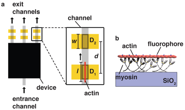
In many of the above applications it is essential to detect, with low error rate, the passing of a given filament at certain positions along a track. This can be required to enable steering into a certain direction at a junction (for example in molecular sorting) or to detect changes in velocity (for example in drug-discovery or diagnostic devices). A particularly demanding and potentially high-impact application of the detection of motor-driven filaments is in biocomputation24,25. Here, a combinatorial problem (such as the subset-sum problem23) would be encoded into a physical channel network including switches or nodes. Using many motile agents that explore all possible pathways present in this network (for simplicity represented as a black box in Fig. 1), a large problem can be solved in a highly parallel manner, and potentially faster than in traditional computers24,25. A solution is represented by the subset of exits from which motile agents emerge (Fig. 1). Thus, the number of filaments emerging from a potentially very large number of exits must be counted efficiently and accurately.
Figure 1. Schematic view of proposed readout regions in a future device, such as a biocomputation device.
a) The device itself is schematically shown as a black box, with entrance and exit channels. Detector points are here indicated at each exit channel of the network (but could be placed at any point of the device, as required by the application). Each detector point consists of a Au line of width w, for FLIC enhancement. The fluorescence originating from actin filaments l, crossing detection regions D1 and D2 from a pair of Au lines, with centre-to-centre spacing d, is read out by one or more CCD pixels each, and cross correlation analysis is used to remove errors from each of the signals. b) Schematic of actin transport by myosin on a SiO2 surface in an in vitro motility assay.
In recent proof-of-principle experiments the motion of motor-driven filaments has usually been tracked step-by-step using image processing21,28,29,30,31. However, in order to take full advantage of the scalability of parallel, motor-driven devices in applications as described above, it is necessary to consider potentially very large and multiplexed networks. In such up-scaled devices it will not be feasible to globally record the motion of all filaments with sufficient resolution and signal-to-noise (S/N) by using standard epifluorescence techniques, and it will computationally not be feasible to track each filament. Instead, a detection system is needed that (i) can monitor a potentially very large number of positions along the nanoscale tracks, (ii) requires a minimum number of sensing channels at each position and (iii) uses S/N enhancement and error correction to reliably detect all filaments.
Here, we develop the key elements of such a local, data-efficient detection system (Fig. 1(a)). Detection points consist of Au lines running perpendicular to a nanofabricated filament-guiding channel. Fluorescence-interference contrast (FLIC, see below) is used to enhance the signal from fluorescently labelled filaments moving across a Au line. This S/N enhancement is additionally improved, by more than one order of magnitude, by cross-correlating the signals from a pair of detectors. The sensing requirements are minimal, requiring the read-out of only one or a few pixels of a CCD device per Au line.
As our molecular-motor system of choice, we use actin filaments powered by myosin attached to the device surface (Fig. 1(b))8. The actomyosin system has the advantages of high speed (up to 10 μm/s, allowing high throughput in future devices) and high flexibility, enabling improved miniaturization of channel networks. In the following we describe the electron-beam lithography (EBL) based fabrication process of the nanochannels and detector Au lines, including the novel use of a hydrogen silsesquioxane (HSQ) layer on top of the Au to support actin motility. We further demonstrate that cross-correlation of the FLIC signals from pairs of Au lines can be used to strongly reduce error rates, and discuss the ideal width and spacing of the Au lines for the detection of individual filaments and for the resolution of filaments moving close to one another.
Results
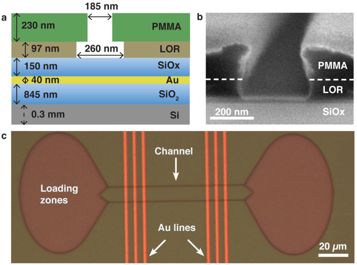
The overall device layout is shown in Figure 2: it consists of nanochannels (Fig. 2(a)), with a slight undercut for better filament confinement (Fig. 2(b))4 , that lead across a series of Au lines used for FLIC enhancement. Large open areas, so called loading zones (Fig. 2(c)), are used to locally bind myosin and actin, with high density, to the surface. Filaments move across the myosin-coated surface, and are guided to the channels by the funnel shape of the loading zones4. See Methods for fabrication details.
Figure 2. Nanochannels for filament guiding with Au lines for FLIC detection.
a) Cross-section of nanochannel with Au line. Approximate thicknesses of resist layers: polymethyl methacrylate (PMMA) and lift-off resist (LOR), and widths of channels similar to (b) are indicated. b) Scanning electron micrograph of nanochannel profile. Coating with 10 nm Pt for SEM viewing. c) Bright field image of overview of one device with two loading zones connected by two parallel nanochannels. Au lines (w = 2 μm, see Fig. 1) run perpendicular to channels, with Au-line centre-to-centre spacing of d = 5 μm.
Fluorescence interference contrast
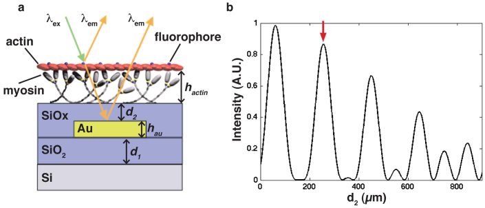
FLIC creates contrast by destructive and/or constructive interference of light reflected off the substrate surface. Here we make use of FLIC to locally enhance the fluorescence signal of the filaments passing over Au lines (see Fig. 3 and Methods for more information). In Figure 4 we show data of the fluorescence intensity observed, as a function of position, in a detection area as a filament moves across a pair of Au lines. Firstly, the data establish actomyosin motility on top of trimethylchlorosilane (TMCS)-derivatized SiOx deposited by HSQ. Second, a clear peak of the optical intensity was observed when an actin filament was on top of the Au line thus establishing the potential of the FLIC-based detection of actin filaments.
Figure 3. Schematic of FLIC concept and response curve for enhancement of filament contrast.
a) Myosin on the SiOx surface transports fluorescently labelled actin filaments at a height, hactin, above the SiOx surface. Incoming light excites the labelled actin filament causing fluorescence emission. Emitted light (λem) can travel directly to the detector or indirectly via reflection from the Au surface. Enhancement of fluorescence results if the two emission signals are in phase. The combination of reflective surfaces can be used to manipulate the fluorescence signal both on and off the Au lines. b) Varying the thickness, d2, shows the theoretical maximum and minimum intensities due to FLIC, see equation (2). Excitation λex and emission λem wavelengths are 540 and 605 nm for Tetra methyl Rhodamine Iso-Thiocyanate (TRITC) filter. Red arrow indicates corresponding thickness used for enhanced TRITC fluorescence on top of Au (see Fig. 4).
Figure 4. Enhanced fluorescence contrast of actin filament in nanochannel.
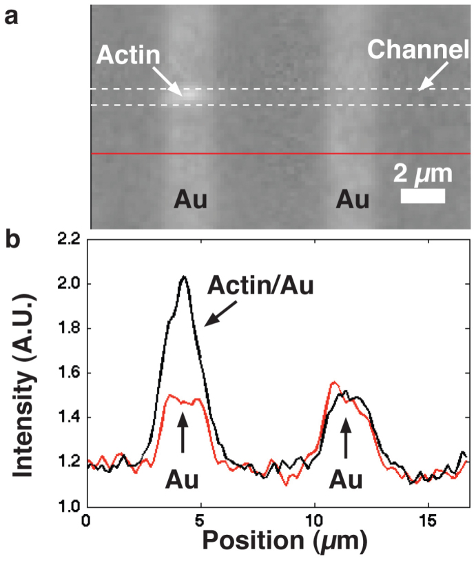
a) An actin filament labelled with RhPh was imaged using a TRITC filter. The approximately l = 2.5 μm long filament passed over the w = 2 μm wide Au lines, with d2 = 240 nm (see Fig. 3), and there became brighter. b) fluorescence profile along the actin-guiding channel (dashed white lines in (a)) and below channel region (red line in (a)). A single pixel line along the centre of the channel was used to create the profiles shown.
Cross correlation
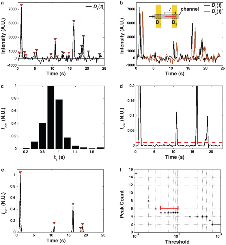
In an actual device with many filament-detection points, it is desirable to optically read out only a small region (such as D1, see Fig. 1(a)), in order to minimize the amount of data to be processed, and to increase achievable feature density. The black line in Figure 5(a) shows the background-subtracted fluorescence signal D1(t) measured in area D1 as a function of time as a number of filaments pass through the detection region. Filaments can then be counted directly from the number of detection peaks, but at the risk of introducing errors: free filaments floating by in solution can give false positives, and short or weakly fluorescing filaments may be difficult to distinguish from background noise. Also, a short dip in fluorescence between two closely spaced filaments can be difficult to distinguish from noise-related features. We therefore used a cross-correlation analysis technique to strongly enhance the S/N ratio. We achieved this by including two Au lines, separated by 5 μm (inset to Fig. 5(b)) as individual detector regions, and obtained fluorescence signals, D1(t) and D2(t), from each detector (D1 and D2 in the inset to Fig. 5(b)), shown as the black and the brown line, respectively in Figure 5(b).
Figure 5. Cross correlation of FLIC signals for single filament detection.
a) Time series trace of fluorescence recorded in detector region D1 as filaments move over the Au line. Red arrows: peaks identified using the same peak-finding algorithm as in (e), resulting in many false positives: according to visual inspection, five filaments passed by the detector. A constant background was subtracted from the data. b) Background-subtracted fluorescence recorded in detector regions D1 and D2, each consisting of one Au line (w = 2 μm), with d = 7 μm (see Fig. 1). Inset: Schematic of detector regions. c) Cross correlation signal Icorr (see equation (1)) of the D1(t) and D2(t) signals from (b), as a function of ts, indicating that Icorr is maximal for ts,max = 0.8 s. d) The multiplied signal D1(t)*D2(t+ts,max) after normalizing. The dashed line shows the threshold level T = 0.01 used to produce the signal in (e). e) Black curve: Same data as in (d) after subtraction of 0.01 of the maximum. Red arrows: extracted peaks using a peak-finding algorithm (see text). f) Number of peaks identified as a function of the threshold level T applied to the cross correlated data set from (d), spanning from 0.001–0.1 of the maximum. Red bar: a threshold between 0.004 and 0.01 produces the correct result of five filaments.
Clearly, the main features in the fluorescence profiles were similar but separated in time by some delay. Noise, on the other hand, is not correlated between the two signals and can thus be eliminated as described in the following steps.
Background subtraction is first done to reduce effects from bleaching. Here we apply a simple linear fit to the data to find a background signal, which is then subtracted from the data. Next, the cross correlation of the two fluorescence profiles can be described by:
where ts is the total shift used, and tend is the total time recorded minus ts. We shift the signal D2(t) back in time in 0.2 s increments with respect to D1(t). The resulting Icorr as a function of ts is shown in Figure 5(c). The bin size in Figure 5(c) is here set by the frame rate and corresponds also to the expected standard deviation (0.16 s) of filament travel times between the Au lines, resulting from fluctuations in filament velocity (see below). For a time delay of tsmax ≈ 0.8 s (the location of the peak in Fig. 5(c)) the signals originating from the two detectors for the same filament are correlated. This time delay is consistent with Δt = d/v ≈ 0.9 s, based on the measured speed of the filaments v ≈ 8 ± 1.4 μm/s (mean ± SD, n = 10), and the centre-to-centre Au-line spacing of d = 7 μm. The speed is measured from actin filaments transported in the nanochannels on the same surface using a previously described tracking program32.
As a next step, the D2(t) signal is shifted by tsmax = 0.8 s to overlap with the signal D1(t), and the two signals are multiplied. This step effectively suppresses uncorrelated noise, and enhances the correlated, real signal. Finally, the resulting signal is normalized to a maximum peak value of one (Fig. 5(d)).
Now, we wish to automatically extract peaks. We use a simple algorithm that looks for the median value in a window size of 0.4 s (two frames). This window is shifted in steps of 0.2 s (single frames) over the entire data set. The median value is compared to a threshold of T, chosen here to be T = 0.01, taken as a fraction of the normalized data set. If the median value is less than T, then it is assigned a zero value, if it is higher than or equal to this threshold value, the value at this point is returned (Fig. 5(e), black curve). Finally the peaks are extracted by finding the local maximum over a range of 0.6 s (three frames; Fig. 5(e), red arrows). The number of peaks extracted in this way gives the number of individual filaments that passed by the detector during the observation. For automated data processing it is important that a range of T values gives reliable results. In Figure 5(f) we show that 0.004 < T < 0.01 produces the correct number of filaments, as verified by direct viewing. A T value outside this range produces false positives (for T < 0.004) or misses filaments (for T > 0.01).
For comparison, we use the same peak finding method as in Figure 5(e) but applied to data (D1(t)) from only one detector. The result is shown by red arrows in Figure 5(a). Clearly, a large number of false positives is produced, which are effectively eliminated by the above cross-correlation method. Whereas more advanced peak finding algorithms exist33,34,35, for transparency, we here used a simple method to illustrate the process. Our results demonstrate that the correlation technique effectively suppresses false positives, which will be relevant in the context of any peak-finding algorithm. To quantify the improvement achieved by cross-correlation we compare the S/N ≈ 12 in Figure 5(a), (based on the average peak maximum of 3838 A.U. and the variance of the noise of 317 A.U.) to that observed after application of cross-correlation (Fig. 5(d), S/N ≈ 222). Here we find an improvement of more than an order of magnitude. Note that, in principle, a similar algorithm could also be used to detect the fact that two filaments arrive at the same time. In this case, one would introduce a threshold value distinguishing the intensity from one and two filaments.
Device design
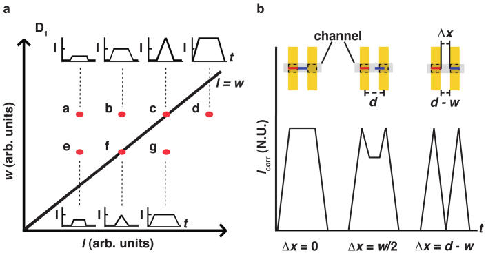
In the following, we discuss how to optimize the signal strength (and thus the S/N ratio) and the ability to resolve two close-by filaments, depending on filament length (l) and the detector geometry as described by w and d (see Fig. 1). We first consider a single Au line (Fig. 6(a)). Short filaments (l < w) will produce a lower, total FLIC-signal strength, than the optimal value that is achieved for l ≈ w (see Fig. 6(a), points a–c). In other words, filaments shorter than the fixed detector width will not yield the maximum possible FLIC-signal, simply due to the fact that they will not fill the detection window at any given time as they pass over it. Filaments with l > w will not produce a stronger signal, but will only broaden the peak (see point d in Fig. 6(a)). This is true, due to the fact that, for filaments longer than the fixed detector width, a maximum FLIC-signal is reached already when the filament has filled the detection window, and therefore the signal cannot increase further as the filament continues to pass over the detection region. Consequently, decreasing w further reduces the signal strength that can be achieved (points e–g). If we therefore assume l = w to be optimal for signal strength, we can set limits on the average filament spacing Δx and the line width w. When the condition Δx > l + w/2 ≈ (3/2)w is fulfilled, the signal between two filaments becomes zero, fully resolving the peaks. A somewhat less conservative requirement is Δx > w. If we then take into consideration that a minimum between two peaks can be fully resolved only if at least three data points are recorded, we obtain an additional condition in the time domain Δt = Δx/v > 3f, where f is the time between frames recorded by the camera, and v is the velocity of the filaments. This second condition can be written as Δx > 3fv and is limited by the speed of the camera.
Figure 6. Schematic of signal dependence on filament length l and detector line width w as shown in Figure 1(a).
a) Schematic map of expected signal intensity in different locations (labelled a–g) in {l, w} parameter space for single filaments. For increasing filament length l (a–b) maximum intensity is obtained for l = w (c). Filaments with l > w (d) will not yield a higher intensity; they will only have the same intensity for a longer time. Decreasing w decreases signal amplitude (e–g). b) Study of the ability of a pair of detector lines to resolve two filaments travelling with end-to-end distance Δx and with l = w for optimal signal strength as a function of Δx. Two fully resolved peaks are obtained for Δx = d − w. Inset: schematic of detector geometry and filament end-to-end spacing Δx.
For a two-line detector system (Fig. 6(a)), with the assumption that l = w for optimal signal strength, geometry requires a centre-to-centre line spacing of at least d > w and we assume a reasonable d = 2w. The signal Icorr from a pair of detectors (see Fig. 6(b)) will yield two fully separated peaks for two filaments with Δx > d – w or Δx > w = l, using the above assumptions. In this context it is worth noting that, for actin, in standard IVMA procedures, we must require that l > 1 μm so that actin filaments maintain motility in the absence of methylcellulose on the surface36. These are suitable conditions8,37 for relevant nanotechnological applications involving actomyosin. In conclusion, the optimal detector design has pairs of detector lines of width l ≈ w and with Δx > w.
Discussion
The FLIC method described here is intended for use in devices where large numbers of filaments need to be accurately and automatically recorded in very many different locations of a device, and with minimal data acquisition, for example in a scalable, highly parallel device. We demonstrated the use of pair-wise detection combined with cross-correlation analysis and thresholding for automatic extraction of filament counts, leading to an increase of the S/N ratio by more than an order of magnitude. The use of FLIC to enhance the signal strength in the detector regions enabled an additional increase of S/N ratio by a factor of 2. In total, the techniques described here thus demonstrate an improvement of S/N by approximately a factor of 36 compared to standard epifluorescence detection. We believe that these findings can be applied as a platform on which diagnostics, drug discovery and, as discussed here, biocomputation can be carried out.
Methods
Device design
The overall fabrication process for the device shown in Figure 2 was as follows. The Si substrate is subjected to wet thermal oxidation forming a layer of SiO2 of approximately 845 nm. Lift off resist, LOR 0.7A, (Microchem Corp., Newton, MA, USA) is added by spin coating at 1500 RPM for 30 seconds, with subsequent baking at 180°C for 15 minutes on a hotplate. Next, polymethyl methacrylate, PMMA 950A5 (Microchem Corp., Newton, MA, USA) is spin coated on top at 6000 RPM for 60 seconds, followed by baking at 160°C for 15 minutes. This double resist layer is exposed to EBL (Raith 150, Dortmund, Germany) for formation of the Au line pattern. After exposure, the PMMA is developed with methyl isobutyl ketone and isopropanol MIBK:IPA (Merck KGaA, Darmstadt, Germany) at a ratio of 1:3 for one minute, followed by rinsing with IPA for 30 seconds. Next, the sample is subject to O2 plasma ashing in a Plasma Preen at 5 mBar for 15 seconds. This plasma ashing step is to remove possible residues of PMMA from the top of the LOR layer before etching. Then, the LOR layer is etched with MF-319:H20 (Microposit MF-319 Developer, Rohm and Haas Electronic Materials, Coventry, UK) in the ratio (1:1) for 4 minutes and rinsed with H2O for 30 seconds to halt the etching of LOR. Cr (used as a sticking layer) and Au are evaporated on the surface to thicknesses of 2 and 40 nm, respectively. The unwanted metal (outside the pattern) and the resists are removed from the surface during a lift off process in Remover 1165 (Microposit Remover 1165, Rohm and Haas Electronic Materials, Coventry, UK) at 80°C on a hotplate, with subsequent rinsing in H2O, leaving behind the desired Au pattern. HSQ; 6% in MIBK, (XR-1541, Dow Corning, USA) is then spun on top at 1500 RPM for 30 s and baked at 350°C on a hotplate to convert the resist into a SiO2-like layer, see below. A second layer of HSQ; 4% in MIBK, is then spun on top at 4500 RPM and baked at 350°C on a hotplate to convert the resist into a SiO2-like layer, resulting in a total thickness of d2 = 240 nm (see Fig. 3(a)). Nanochannel and loading zone patterns are produced in the same way as the Au line pattern. A cross section of the nanochannel is shown in Figure 2(a).
Fluorescence interference contrast
FLIC is illustrated in Figure 3: fluorophores are excited directly from a source of wavelength λex, or indirectly by light reflected from a surface (Si or Au in Fig. 3). Light of wavelength λem, emitted from the fluorophores, can travel to the camera directly or indirectly after reflection from the Au surface, after travelling through a semi-transparent oxide layer of SiO2 (thickness d2, see Fig. 3a). Differences in the optical pathways of indirect and direct emission pathways give rise to a phase shift causing either constructive or destructive interference38,39,40, enhancing or quenching the fluorescence respectively. Here, we are interested in constructive interference on top of Au lines, in order to enhance the fluorescence signal of fluorescently labelled filaments crossing the Au line. Calculation of the fluorescent intensity was performed as in38, according to:
where excitation and emission wavelengths were 540 nm and 605 nm, respectively, index of refraction for water and SiO2 were nw = 1.333 and nSiO2 = 1.46, and for a fluorophore height of hactin = 40 nm, i.e. the height that actin is held above the surface41. This fluorescence intensity as a function of d2 indicates the first fluorescence maxima at approximately d2 = 50 nm and d2 = 240 nm above Au, see Figure 3(b). Due to instabilities of very thin HSQ layers, the larger d2 = 240 nm was used. For the thickness of the SiO2 layer on top of the Si substrate (d1 in Fig. 3(a)), we use 845 nm, effectively eliminating any FLIC effect above the Si. If desired, one can additionally use the destructive FLIC effect to eliminate fluorescence off the Au lines, by tuning d1 and d2.
HSQ application
We used the negative-tone resist hydrogen silsesquioxane (HSQ) to coat the Au lines. This resist is transformed into a SiO2–like layer42, when baked at high temperatures or exposed to EBL. HSQ has been used in a variety of applications43,44 and is a suitable substitute for forming SiO2 films by direct deposition45. HSQ can also, as shown here, support actomyosin motility. Here we have chosen to use HSQ as a SiO2 layer due to its ease of use. Other techniques such as atomic layer deposition (ALD) have advantages and drawbacks compared to using HSQ. Using ALD one can apply a highly uniform SiO2 layer, however, due to the deposition method, a repeating sandwich layer of Al2O3 and SiO2 must be used to increase thickness46. This may affect the FLIC signals and has therefore not been considered.
Surface treatments for actomyosin motility
After formation of nanochannels, plasma treatment was used to ensure that the top resist layer of PMMA was sufficiently hydrophilic and therefore unable to support motility5. As a next step, silanization using chemical vapour phase deposition (CVD) of 98% (GC) trimethylchlorosilane, TMCS (Sigma-Aldrich Sweden AB, Stockholm, Sweden) was performed to promote motility on the floor of the loading zones and nanochannels, namely the exposed SiOx substrate28. Caution: TMCS is highly flammable and reacts violently with water! Wetting of the surface was done to reduce the possibility of air bubbles forming in the channels4.
Fluorescence microscopy
Rhodamine Phalloidin (RhPh) labelled filaments were observed using an inverted fluorescence microscope (Nikon, Eclipse TE300) equipped with a 100x oil immersion objective (Nikon, NA 1.4) and a Tetra methyl Rhodamine Iso-Thiocyanate (TRITC) filter set (Ex 540/25, DM 565, BA 605/25). Images were recorded with an EMCCD camera (Hamamatsu C9100) and analyzed with Image J (Rasband, W.S ImageJ, U.S. National Institutes of Health, Bethesda, Maryland, USA, http://imagej.nih.gov/ij/, 1997–2012). Actin filament sliding velocities were calculated using a previously described Matlab algorithm32. This was done by manually following the tip of actin filaments moving in the nanostructured channel. All in vitro motility assays (IVMAs) were performed with the actomyosin system as described previously37,41. In brief, proteins were diluted in buffer A (10 mM MOPS, 1 mM MgCl2, 1 mM DTT, 0.1 mM EGTA, 50 mM KCl, pH 7.4). Flow cells were then incubated as follows: (i) 120 μg/ml HMM for 4 minutes (ii) 1 mg/ml BSA for 1 minute (iii) 1 μM block actin (short and unlabeled actin filaments) in Buffer A with 1 mM ATP for 2 minutes (iv) rinsed with a40 (buffer A with final concentrations of 10 mM DTT and 25 mM KCl, 1 mM ATP, 2.5 mM creatine phosphate, 56 units/ml creatine kinase) (v) rinsed with Buffer A (vi) 100 nM RhPh labelled actin filaments for 1 minute (vii) rinsed with Buffer A (viii) a60 (a40 with final concentrations of 45 mM KCl, 3 mg/ml glucose, 20 units/ml glucose oxidase, 460 units/ml catalase. The motility assays were performed at 26°C.
Author Contributions
M.L. planned the study, performed the experiments, analyzed the results and wrote the paper. LtS performed the experiments and contributed to the analysis. A.M. and H.L. conceived and initiated the study, contributed to the analysis and edited the paper.
Acknowledgments
The work leading to this invention has received funding from the European Union Seventh Framework Programme (FP7/2007-2011) under grant agreement n° 228971 (Molecular Motors-based Nano Devices –MONAD), the Swedish Research Council under grant n° 621-2010-5146, nmC@LU, the Knut and Alice Wallenberg Foundation, and the Carl Trygger's foundation.
References
- Kron S. J. & Spudich J. A. Fluorescent actin filaments move on myosin fixed to a glass surface. Proc. Natl. Acad. Sci. 83, 6272–6276 (1986). [DOI] [PMC free article] [PubMed] [Google Scholar]
- Kron S. J., Toyoshima Y. Y., Uyeda T. Q. & Spudich J. A. Assays for actin sliding movement over myosin-coated surfaces. Methods Enzymol. 196, 399–416 (1991). [DOI] [PubMed] [Google Scholar]
- Howard J., Hudspeth A. J. & Vale R. D. Movement of microtubules by single kinesin molecules. Nature 342, 154–158 (1989). [DOI] [PubMed] [Google Scholar]
- Bunk R. et al. Guiding motor-propelled molecules with nanoscale precision through silanized bi-channel structures. Nanotechnology 16, 710–717 (2005). [Google Scholar]
- Bunk R. et al. Actomyosin motility on nanostructured surfaces. Biochem. Biophys. Res. Commun. 301, 783–788 (2003). [DOI] [PubMed] [Google Scholar]
- Hess H., Clemmens J., Qin D., Howard J. & Vogel V. Light-controlled molecular shuttles made from motor proteins carrying cargo on engineered surfaces. Nano Lett 1, 235–239 (2001). [Google Scholar]
- Hiratsuka Y., Tada T., Oiwa K., Kanayama T. & Uyeda T. Q. Controlling the direction of kinesin-driven microtubule movements along microlithographic tracks. Biophys. J. 81, 1555–1561 (2001). [DOI] [PMC free article] [PubMed] [Google Scholar]
- Sundberg M. et al. Actin filament guidance on a chip: toward high-throughput assays and lab-on-a-chip applications. Langmuir 22, 7286–7295 (2006). [DOI] [PubMed] [Google Scholar]
- Mansson A. et al. In vitro sliding of actin filaments labelled with single quantum dots. Biochem. Biophys. Res. Commun. 314, 529–534 (2004). [DOI] [PubMed] [Google Scholar]
- Ramachandran S., Ernst K. H., Bachand G. D., Vogel V. & Hess H. Selective loading of kinesin-powered molecular shuttles with protein cargo and its application to biosensing. Small 2, 330–334 (2006). [DOI] [PubMed] [Google Scholar]
- Kumar S. et al. Antibodies Covalently Immobilized on Actin Filaments for Fast Myosin Driven Analyte Transport. PLoS ONE 7, e46298 (2012). [DOI] [PMC free article] [PubMed] [Google Scholar]
- Paguirigan A. L. & Beebe D. J. Microfluidics meet cell biology: bridging the gap by validation and application of microscale techniques for cell biological assays. BioEssays 30, 811–821 (2008). [DOI] [PMC free article] [PubMed] [Google Scholar]
- Squires T. M. & Quake S. R. Microfluidics: fluid physics at the nanoliter scale. Rev. Mod. Phys. 77, 977–1026 (2005). [Google Scholar]
- Whitesides G. M. The origins and the future of microfluidics. Nature 442, 368–373 (2006). [DOI] [PubMed] [Google Scholar]
- Wang J. Cargo-towing synthetic nanomachines: towards active transport in microchip devices. Lab Chip 12, 1944–1950 (2012). [DOI] [PubMed] [Google Scholar]
- van den Heuvel M. G. L. & Dekker C. Motor proteins at work for nanotechnology. Science 317, 333–336 (2007). [DOI] [PubMed] [Google Scholar]
- Takatsuki H. et al. Transport of single cells using an actin bundle–myosin bionanomotor transport system. Nanotechnology 22, 245101 (2011). [DOI] [PubMed] [Google Scholar]
- Patolsky F., Weizmann Y. & Willner I. Actin-based metallic nanowires as bio-nanotransporters. Nat. Mater. 3, 692–695 (2004). [DOI] [PubMed] [Google Scholar]
- Agarwal A. & Hess H. Biomolecular motors at the intersection of nanotechnology and polymer science. Prog. Polym. Sci. 35, 252–277 (2010). [Google Scholar]
- Fischer T., Agarwal A. & Hess H. A smart dust biosensor powered by kinesin motors. Nat. Nanotech. 4, 162–166 (2009). [DOI] [PubMed] [Google Scholar]
- van den Heuvel M. G., de Graaff M. P. & Dekker C. Molecular sorting by electrical steering of microtubules in kinesin-coated channels. Science 312, 910–914 (2006). [DOI] [PubMed] [Google Scholar]
- Meyhofer E. & Howard J. The force generated by a single kinesin molecule against an elastic load. Proc. Natl. Acad. Sci. U. S. A. 92, 574–578 (1995). [DOI] [PMC free article] [PubMed] [Google Scholar]
- Nicolau D. V. Jr, Burrage K. & Nicolau D. V. Computing with motile bio-agents. Proc. SPIE-Int. Soc. Opt. Eng. 6416 (2007). [Google Scholar]
- Nicolau D. V. et al. Molecular motors-based micro- and nano-biocomputation devices. Microelectron Eng 83, 1582–1588 (2006). [Google Scholar]
- Nicolau D. V. Jr & Nicolau D. V. Biocomputation schemes based on the directed and directional movements of motile biological objects. Proc. SPIE 5651, 134–143 (2005). [Google Scholar]
- Adleman L. M. Molecular computation of solutions to combinatorial problems. Science 266, 1021–1024 (1994). [DOI] [PubMed] [Google Scholar]
- Rozenberg G. & Salomaa A. Vol. 1644 Lecture Notes in Computer Science (eds Jirí Wiedermann, Peter van Emde Boas,, & Mogens Nielsen) 106–118 (Springer Berlin/Heidelberg, 1999). [Google Scholar]
- Sundberg M. et al. Silanized surfaces for in vitro studies of actomyosin function and nanotechnology applications. Anal. Biochem. 323, 127–138 (2003). [DOI] [PubMed] [Google Scholar]
- Ruhnow F., Zwicker D. & Diez S. Tracking single particles and elongated filaments with nanometer precision. Biophys. J. 100, 2820–2828 (2011). [DOI] [PMC free article] [PubMed] [Google Scholar]
- Ernest N. C., Wall R. A., Jed C. M. & George H. Speckled microtubules improve tracking in motor-protein gliding assays. Phys. Bio. 4, 10 (2007). [DOI] [PMC free article] [PubMed] [Google Scholar]
- Hamelink W., Zegers J. G., Treijtel B. W. & Blangé T. Path reconstruction as a tool for actin filament speed determination in the in vitro motility assay. Anal. Biochem. 273, 12–19 (1999). [DOI] [PubMed] [Google Scholar]
- Mansson A. & Tagerud S. Multivariate statistics in analysis of data from the in vitro motility assay. Anal. Biochem. 314, 281–293 (2003). [DOI] [PubMed] [Google Scholar]
- Haustein E. & Schwille P. Fluorescence correlation spectroscopy: novel variations of an established technique. Annu. Rev. Biophys. Biomol. Struct. 36, 151–169 (2007). [DOI] [PubMed] [Google Scholar]
- Du P., Kibbe W. A. & Lin S. M. Improved peak detection in mass spectrum by incorporating continuous wavelet transform-based pattern matching. Bioinformatics 22, 2059–2065 (2006). [DOI] [PubMed] [Google Scholar]
- Pyenta P. S., Holowka D. & Baird B. Cross-correlation analysis of inner-leaflet-anchored green fluorescent protein co-redistributed with IgE receptors and outer leaflet lipid raft components. Biophys. J. 80, 2120–2132 (2001). [DOI] [PMC free article] [PubMed] [Google Scholar]
- Toyoshima Y. Y., Kron S. J. & Spudich J. A. The myosin step size: measurement of the unit displacement per ATP hydrolyzed in an in vitro assay. Proc. Natl. Acad. Sci. 87, 7130–7134 (1990). [DOI] [PMC free article] [PubMed] [Google Scholar]
- Sundberg M. et al. Selective spatial localization of actomyosin motor function by chemical surface patterning. Langmuir 22, 7302–7312 (2006). [DOI] [PubMed] [Google Scholar]
- Parthasarathy R. & Groves J. T. Optical techniques for imaging membrane topography. Cell Biochem. Biophys. 41, 391–414 (2004). [DOI] [PubMed] [Google Scholar]
- Lambacher A. & Fromherz P. Luminescence of dye molecules on oxidized silicon and fluorescence interference contrast microscopy of biomembranes. J Opt Soc Am B 19, 1435–1453 (2002). [Google Scholar]
- Kerssemakers J., Howard J., Hess H. & Diez S. The distance that kinesin-1 holds its cargo from the microtubule surface measured by fluorescence interference contrast microscopy. Proc. Natl. Acad. Sci. U. S. A. 103, 15812–15817 (2006). [DOI] [PMC free article] [PubMed] [Google Scholar]
- Persson M. et al. Heavy meromyosin molecules extending more than 50 nm above adsorbing electronegative surfaces. Langmuir 26, 9927–9936 (2010). [DOI] [PubMed] [Google Scholar]
- Yang C.-C. & Chen W.-C. The structures and properties of hydrogen silsesquioxane (HSQ) films produced by thermal curing. J. Mater. Chem. 12, 1138–1141 (2002). [Google Scholar]
- Namatsu H. et al. Three-dimensional siloxane resist for the formation of nanopatterns with minimum linewidth fluctuations. J. Vac. Sci. Technol., B 16, 69–76 (1998). [Google Scholar]
- Egard M. et al. High transconductance self-aligned gate-last surface channel In0.53Ga0.47As MOSFET. Proc. IEEE IEDM, 13, 12.11–13.12.14 (2011). [Google Scholar]
- Arkles B. et al. Staged development of modified silicon dioxide films. J. Sol-Gel Sci. Technol. 8, 465–469 (1997). [Google Scholar]
- Hausmann D., Becker J., Shenglong W. & Gordon R. G. Rapid vapor deposition of highly conformal silica nanolaminates. Science 298, 402 (2002). [DOI] [PubMed] [Google Scholar]


