Abstract
Purpose
To compare intracavitary brachytherapy dose estimation for organs at risk (bladder and rectum) based on semi-orthogonal reconstruction of radiographs on non-isocentric X-ray unit and Computed Tomography (CT) – based volumetric planning in cervical cancer.
Material and methods
Bladder and rectal points as per International Commission on Radiation Units and Measurements (ICRU) report 38, were retrospectively evaluated on 15 high dose rate intracavitary brachytherapy applications for cervical cancer cases. With the same source configuration as obtained during planning on radiographs performed on a non-isocentric X-ray unit, the mean doses to 2cc of most irradiated part of bladder and rectum were computed by CT planning and these estimates were compared with the doses at ICRU bladder and rectal points.
Results
The mean ICRU point dose for bladder was 3.08 Gy (1.9-5.9 Gy) and mean dose to 2 cc (D2cc) bladder was 6.91 Gy (2.9-12.2 Gy). ICRU rectal dose was 3.8 Gy (2.4-4.45 Gy) and was comparable with D2cc rectum dose 4.2 Gy (2.8-5.9 Gy). Comparison of mean total dose (ICRU point vs. D2cc) for each patient was found to be significantly different for bladder (p = 0.000), but not for rectum (p = 0.08).
Conclusions
On comparison of ICRU point based planning with volumetric planning on CT, it was found that bladder doses were underestimated by the film based method. However, the rectal doses were found to be similar to the D2cc doses. The results with non isocentric film based treatment planning were similar to the existing literature on orthogonal film based simulator planning.
Keywords: bladder dose, brachytherapy, cervical cancer, radiograph, rectal dose
Purpose
High Dose Rate (HDR) brachytherapy in the treatment of cervical cancer with or without external radiotherapy is an essential component of management. It has a high therapeutic index delivering a high dose to primary cervical lesion and lower doses to adjacent organs [1–3]. In brachytherapy, an exact knowledge of the applicator geometry is necessary for an accurate calculation of dose to tumor and critical organs [4]. The traditional ways to reconstruct the brachytherapy catheters are either using a semi-orthogonal film method with a reconstruction jig or a pair of isocentric orthogonal or variable angle X-ray imaging method. X-ray images are obtained by using a therapy simulator or an integrated brachytherapy unit (IBU). Except IBU, the procedure requires that the patient is transferred after the application to the X-ray unit room for obtaining the reconstruction images and needs to be transported back to the brachytherapy treatment room to administer the irradiation. A modern approach in treatment planning for cervical cancer is based on Computed Tomography (CT) or Magnetic Resonance (MR) images and on a 3D dose calculation. Since 2004, several guidelines for image based brachytherapy for cervical cancer have been published [2, 5, 6].
At our centre, intracavitary brachytherapy (ICBT) planning has been carried with the 2D X-ray film method using a reconstruction jig and semi orthogonal reconstruction. The present study was carried out with the intention of changing over to CT based 3D planning. The treatments delivered using 2D film planning were also planned with CT imaging keeping the same source configuration. The doses to organs at risks i.e. bladder and rectum were computed by both the methods for further analysis. To our knowledge, there has been limited published data or literature available regarding the dosimetric comparison of semi orthogonal reconstruction of non isocentric X-rays with orthogonal X-rays or CT-MRI brachytherapy treatment planning in cervical cancers.
Material and methods
Patients selection
Ten patients with cervical cancer (Stage IIB – 4 patients, Stage IIIB – 4 patients, Stage IVA – 2 patients) who underwent 30 intracavitary brachytherapy insertions at our centre were included in this study. Treatment planning was done with conventional planning with a reconstruction jig. A preliminary study of CT guided volumetric planning has been performed retrospectively. This study was approved by the hospital's ethical committee.
Treatment scheme
The standard treatment protocol for cervical cancers at our centre consists of external beam radiotherapy (50 Gy/ 25 fractions) with concomitant chemotherapy and ICBT. After 7-10 days of completion of external chemo-radiotherapy to the pelvis, patients were taken for HDR-ICBT and a total dose of 21 Gy in three equal fractions of 7 Gy each at weekly intervals was given.
Brachytherapy insertion
The Fletcher Williamson applicators (Nucletron, Veenendaal, The Netherlands®) were used for intracavitary brachytherapy application consisting of uterine tandem and a pair of ovoids. Standard metallic applicators were used without special modification for CT/MRI compatibility. Before each application, a urinary catheter was inserted and the catheter balloon inflated with contrast and normal saline (7 ml) for visualizing the bladder. Appropriate packing was done to fix the applicator in position and to push the bladder and rectum away from the vaginal applicators. Bladder and rectal reference points were identified according to ICRU 38 recommendations. The patients were under conscious sedation.
Brachytherapy planning and treatment: conventional planning
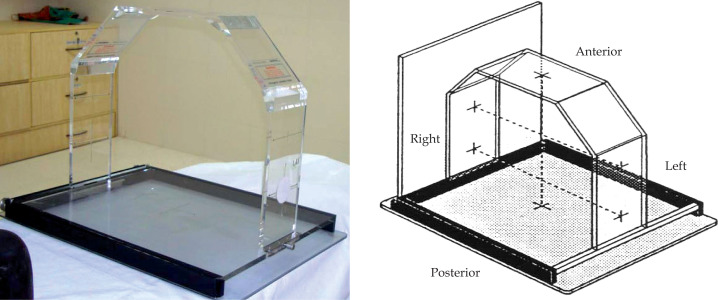
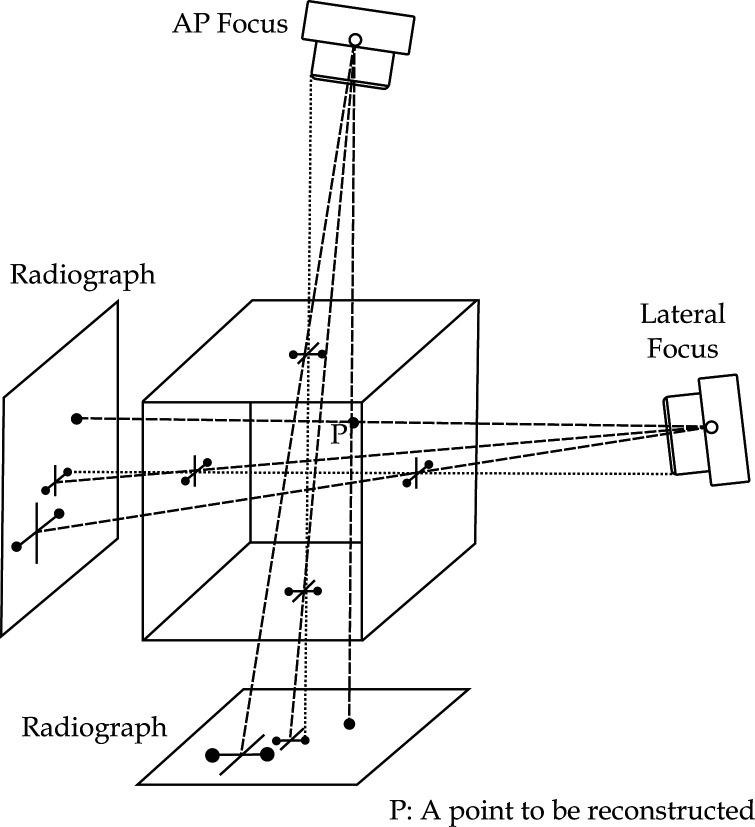
After insertion of the applicators, X-ray images were taken with patient in supine position (AP and lateral views) for conventional planning with a reconstruction jig. To minimize patient movement during radiographs, the reconstruction jig base plate was kept below the patient and it remained there till the treatment was completed. The reconstruction jig (Fig. 1) was supplied by Nucletron® and comprises of a base plate and a C shaped mountable structure. The base and side plates are embedded with radio opaque markers at known positions. These markers appear as a straight line with circular dots on radiographic films. The X-ray tube is focused on the markers on upper C-shaped plate. The base plate also has a provision for holding the radiographic film cassettes for lateral as well as AP radiographs. The brachytherapy treatment planning systems require setup parameters, with magnification factors of the images. Semi orthogonal reconstruction method is used for reconstruction of the images. This method allows the use of a non isocentric X-ray unit to take the two reconstruction radiographs. Truly orthogonal orientations are not easily obtained with non isocentric X-ray unit. A localization jig with AP and lateral cross wires is placed over the patient and radiographs are taken. The semi orthogonal reconstruction method accepts X-rays beams whose central axes do not intersect and are not perpendicular to one another. The only requirement is that the projections of the cross-wires on the two corresponding box faces are visible on the radiographs (Fig. 2).
Fig. 1.
X-ray images were taken with patient in supine position (AP and lateral views) for conventional planning
Fig. 2.
The semi orthogonal reconstruction method accepts X-rays beams whose central axes do not intersect and are not perpendicular to one another
Geometrical reconstruction of applicator and dose computation was carried out using PLATO SUNRISE (Brachytherapy v14.3.5, Nucletron, The Netherlands®) brachytherapy treatment planning system using Vidar Dosimetry Pro scanner. The films were scanned with scanner. Point A was defined on the radiographs as being 2 cm superior (along the tandem) to the flange abutting external cervical os and 2 cm lateral from the axis of the tandem. The source positions were loaded as per the standard loading pattern in accordance with the Manchester System. These dwell positions were then optimized to minimize the dose to rectal and bladder points. The 7 Gy dose was prescribed to point A. The doses to point A, bladder and rectum were calculated. In the planning process, bladder and rectum point doses were planned to keep below 80% of dose to point A for each planned fraction.
3D CT post treatment planning
A CT scan (Somatom Sensation 4, Siemens®) with 3 mm slice thickness through the pelvis was performed for 15 cases out of 30 ICBT insertions. The CT images were transferred to Oncentra Virtual Simulation System (Oncentra MasterPlan version 3.3, Nucletron®) via networking and subsequently to the Plato Treatment Planning System (Nucletron®). The patient was shifted to the treatment chamber and treatment was delivered by MicroSelectron – HDR (Nucletron®) as per the conventional planning. Subsequently the radiation oncologist delineated the bladder and rectum (OARs) in each slice of all the CT images. Although few CT slices contained artefacts, but this was not a serious impediment to contouring bladder and rectum in this study. Rectum was contoured from above the anal sphincter to the level of transition to sigmoid. The entire bladder was contoured. After catheter reconstruction, for each application, the corresponding optimized dwell positions used in conventional 2D planning were duplicated for 3D planning with the contours now drawn. DVH parameters for minimum dose to the most irradiated contiguous volume of 0.1cc, 1cc and 2cc (D0.1cc, D1cc and D2cc, respectively) were produced for each OAR with 100 000 sample points. No contouring was done during actual treatment planning.
Statistical analysis
The paired Student's t-test was performed for comparison of ICRU point doses and D2cc volume doses for bladder and rectum. Mean ratio (D2cc/ICRU) was also calculated.
Results
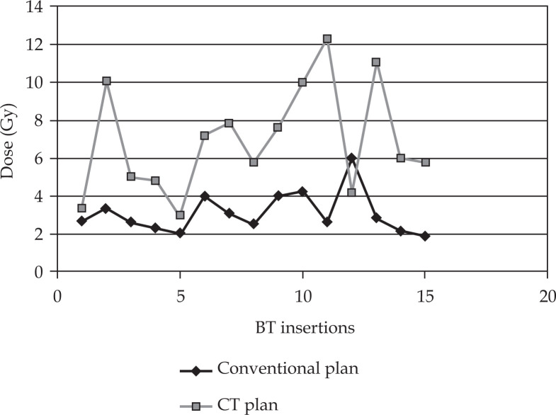
The mean age of the patients was 55 (range 45-60) years. Tumor stage was evaluated according to the International Federation of Gynaecology and Obstetrics (FIGO) classification [7]. The mean contoured volume of bladder and rectum was 104 (± 64) cc and 48 (± 13) cc, respectively. Table 1 shows the mean ICRU point doses and D2cc volume doses for bladder and rectum from this study. The mean D2cc of the bladder obtained from the CT plan was 6.91 Gy (2.9-12.2 Gy). The mean ICRU bladder dose obtained for our patients was 3.08 Gy (1.9-5.9 Gy). Our results reveal that ICRU bladder dose is less than bladder D2cc dose by a ratio of 2.24 (Fig. 3). Mean ICRU and D2cc doses calculated show a statistically significant difference for bladder (p = 0.000).
Table 1.
Mean ICRU point Doses and D2cc volume doses in bladder and rectum in our study (semi orthogonal method)
| Mean (range) ICRU (Gy) | Mean (range) D2cc (Gy) | Paired t-test (range) | Average ratio (D2cc/ICRU) | |
|---|---|---|---|---|
| Bladder | 3.08 (1.9-5.9) | 6.91 (2.9-12.2) | p = 0.000, CI (2.29-5.38) | 2.24 ± 1.01 |
| Rectum | 3.8 (2.4-4.45) | 4.2 (2.8-5.9) | p = 0.08, CI (–0.15-0.91) | 1.10 ± 0.229 |
ICRU – International Commission on Radiation Units and Measurements; D2cc – dose received by 2cc of the volume of the bladder calculated from image based CT planning; CI – confidence interval
Fig. 3.
Comparison of bladder dose by conventional and CT planning
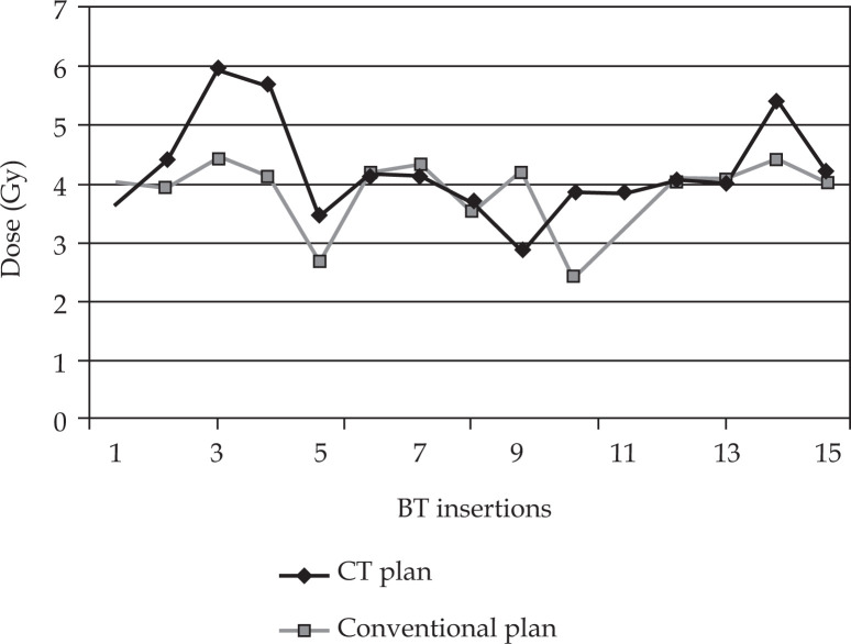
The mean D2cc of the rectum obtained from the 3D plan was 4.2Gy (2.8-5.9 Gy). The mean ICRU rectal dose obtained from the conventional plan for all patients was 3.8 Gy (2.4-4.45 Gy) (Table 2, Fig. 4). Mean ICRU and D2cc doses calculated did not reveal a statistically significant difference for rectum (p = 0.08). The average ratio in this study was 1.10. Physical doses (EBRT + HDR) for OARs at ICRU points as well D2cc were converted to a biologically equivalent dose and normalised to conventional 2Gy (α/β = 3), EQD2 (Table 3).
Table 2.
Mean ICRU point doses and D2cc volume doses in bladder and rectum (orthogonal method)
| Bladder | Rectum | |||||
|---|---|---|---|---|---|---|
| Mean (range) ICRU (Gy) | Mean (range) D2cc (Gy) | Average Ratio (range) (D2cc/ ICRU) | Mean (range) ICRU (Gy) | Mean (range) D2cc (Gy) | Average Ratio (D2cc/ICRU) | |
| Onal et al. [12] | 6.1 (2.9-8.7) | 9.2 (7.6-12.9) | 1.51 | 5 (2.2-10.7) | 8.3 (5.1-12.3) | 1.66 |
| Jamema et al. [13] | 4.56 | 7.12 | 1.56 ± 0.6 | 4.63 | 5.16 | 1.11 ± 0.2 |
| Tan et al. [14] | 2.9 (1.2-4.5) | 3.9 (1.3-6.3) | 1.34 ± 0.34 | 3.4 (2.4-4.2) | 3.6 (1.8-5.9) | 1.07 ± 0.25 |
ICRU – International Commission on Radiation Units and Measurements; D2cc – dose received by 2cc of the volume of the bladder calculated from image based CT planning
Fig. 4.
Comparison of rectal dose by conventional and CT planning
Table 3.
Biologically normalized total dose EQD2 for bladder and rectum (α/β = 3) in our study
| OAR'S | ||
|---|---|---|
| Bladder Mean (range) (Gy) | Rectum Mean (range) (Gy) | |
| ICRU Point | 54 ± 2 (51.8-60.7) | 55 ± 1 (52.6-56.6) |
| D2cc | 65 ± 10 (87.5-53.5) | 56 ± 2 (53.3-60.6) |
Discussion
Intracavitary brachytherapy is an integral part of the treatment of cervical cancer. The treatment planning for the delivery of radiation is dependent on the imaging modality used as well as the method of reconstruction of the applicators and organ at risk. Orthogonal radiographs are traditionally used for treatment planning. However, semiorthogonal reconstruction especially in the context of C-arm based brachytherapy planning has also been used. There is limited literature available on non-isocentric radiography based intracavitary brachytherapy planning especially with respect to volumetric dosimetry. Extensive literature is available which clearly suggests that image based brachytherapy is better than point based brachytherapy. The starting point was to retrospectively evaluate our clinical practice by applying 3D assessment of the OARs using CT scans.
Fung [8] has evaluated the reconstruction jig with a C-arm based mobile fluoroscopic unit and found that the jig not only has an excellent accuracy of reconstruction, but it also resolves problems encountered while using C-arm. Both Fung [8] and Cuijpers [9] have suggested that using the jig resolves the problem such as distortion, ill defined planes and sagging, which are issues with image intensifier used in C-arm fluroscopic units. They have reported that the reconstruction jig is narrow and the localization of the marker point becomes difficult for very bulky patients. Nevertheless, in our study our patients did not experience any difficulty in fitting within the jig possibly due to the smaller built of the Indian females as compared to the Western population. In the radiographs taken with the help of reconstruction jig, the bladder and rectal markers were properly visualized in both AP as well as lateral radiographs. However, in some patients the radio opaque markers and contrast in bulb of Foley's catheter were faintly visualized with usual exposure factors and required increasing of the exposure factors (kV, mAs).
For image based dosimetry CT images were used for reconstruction of the applicators. All the patients in this study were treated using standard Fletcher Williamson applicator. The artefacts produced by metal applicators were reduced up to some extent by manipulating the CT window and level setting during CT scan. The accuracy of CT reconstruction was compared with the radiograph based reconstruction of the applicator by overlaying CT reconstruction on radiograph reconstruction. The maximum variation of ± 6 mm was observed between these two with respect to point A. This is attributed to shifting of patient between X-ray room and CT room. It has been shown by Grigsby et al. [10] that movement of reference points relative to bony structures during the interval time of two intracavitary implants led to an average shift of 10-15 mm and dose differences of up to 35% were observed due to this high dose gradient. Thomadsen et al. [11] have also concluded that any movement of patient should be avoided as this can produce large changes in dose to bladder and rectum.
We compared our results of non isocentric film based ICBT using semiorthogonal reconstruction with the data available in the literature where ICBT was performed with orthogonal reconstruction delivering a dose 7 Gy at similar point A (Table 4). We found that our calculations with semiorthogonal radiographs for bladder and rectal doses were comparable to the doses calculated with orthogonal radiography based studies such as Onal et al. [12] (62 HDR applications), Jamema et al. [13], (22 HDR applications) (both authors prescribed 7 Gy dose at Point A) as well as with Tan et al. [14] (55 applications with 5.3 Gy to Point A). When we compared our results for the mean ICRU point doses obtained using semi orthogonal approach and the D2cc doses for rectum and bladder on CT scans, we found that the average ratio of ICRU rectal dose to D2cc (rectum) by our approach was 1.10 which is similar to the ratios obtained such as 1.66, 1.11 and 1.07 by other authors [12–14] for rectum, respectively. However, the ICRU bladder point underestimated the bladder D2cc dose by a ratio of 2.24 in our study as compared to 1 .51, 1.56 and 1.34 [12–14] (Table 2), but it was comparable with Schoeppel et al. [15] and Barillot et al. [16]. Other authors such as Hunter et al. [17] have also found that the ratio of max bladder dose (from CT images) to ICRU reference dose (calculated from radiographs) varied from 1.01 to 3.59. Schoeppel et al. [15] has reported average ratios of 2.3 (range 1.4-2.7) for the bladder and 1.3 (range 0.9-2.1) for the rectum. Barillot et al. [16] used ultrasonography for evaluating the bladder doses and found that maximum doses in the bladder were on an average 2.7 times higher than the doses at the ICRU reference points (calculated from radiographs).
Table 4.
Comparison of mean ICRU point doses (Gy) for bladder and rectum using semi-orthogonal method and orthogonal method
| Semi-orthogonal method | Orthogonal method | ||
|---|---|---|---|
| Present study (n = 15) | Onal et al. [12] (n = 63) | Jamema et al. [13] (n = 22) | |
| Point A (Gy) | 7 | 7 | 7 |
| Bladder Mean | 3.08 | 6.1 | 4.56 |
| (range) (Gy) | (1.9-5.9) | (2.9-8.7) | |
| Rectum Mean | 4.2 | 5 | 4.63 |
| (range) (Gy) | (2.8-5.9) | (2.2-10.7) | |
n – number of brachytherapy insertions (for a prescription dose of 7 Gy to Point A).
Our results are similar with published data for rectal doses, however there is a broad range for bladder doses. Fellner et al. [18] has attributed the wide range of ratios for the bladder to different methods used like radiographs, ultrasound, CT to evaluate the doses and the difference in individual patient anatomy.
Conclusions
Treatment planning based on semi-orthogonal films obtained with a non-isocentric X-ray unit with the help of a reconstruction jig is comparable to true orthogonal films on an isocentric X-ray unit. ICRU reference point doses by semiorthogonal reconstruction underestimated the bladder D2cc volume doses, but no significant difference was found for rectum. CT/ MRI based 3D volume based planning should be used wherever feasible as it is better in assessing the doses to OAR volumes than conventional film point based 2D planning and has today become the standard of care in many institutions.
References
- 1.Atahan I L, Onal C, Ozyar E, et al. Long-term outcome and prognostic factors in patients with cervical carcinoma: a retrospective study. Int J Gynecol Cancer. 2007;17:833–842. doi: 10.1111/j.1525-1438.2007.00895.x. [DOI] [PubMed] [Google Scholar]
- 2.Nag S. High dose rate brachytherapy: its clinical applications & treatment guidelines. Technol Cancer Res Treat. 2004;3:269–287. doi: 10.1177/153303460400300305. [DOI] [PubMed] [Google Scholar]
- 3.Viani GA, Manta GB, Stefano EJ, et al. Brachytherapy for cervix cancer: low dose rate or high dose rate Brachytherapy – a meta analysis of clinical trials. J Exp Clin Cancer Res. 2009;28:47. doi: 10.1186/1756-9966-28-47. [DOI] [PMC free article] [PubMed] [Google Scholar]
- 4.Chassangne D, Duthyerix A, Almond P, et al. ICRU Report No.38: Dose & Volume specification for reporting Intracavitary therapy in gynecology; Bethesda: International Commissioning on Radiation Units & Measurements; 1985. [Google Scholar]
- 5.Nag S, Cardenes H, Chang S, et al. Proposed guidelines for image-based intracavitary brachytherapy for cervical carcinoma: report from Image-Guided Brachytherapy Working Group. Int J Radiat Oncol Biol Phys. 2004;60:1160–1172. doi: 10.1016/j.ijrobp.2004.04.032. [DOI] [PubMed] [Google Scholar]
- 6.Pötter R, Haie-Meder C, Van Limbergen E, et al. Recommendations from gynecological (GYN) GEC ESTRO working group (II); concepts & terms in 3D image based treatment planning in cervix cancer brachytherapy – 3D dose volume parameters and aspects of 3D image based anatomy, radiation physics, radiobiology. Radiother Oncol. 2006;78:67–77. doi: 10.1016/j.radonc.2005.11.014. [DOI] [PubMed] [Google Scholar]
- 7.American joint Committee on Cancer, AJCC cancer staging manual. 5th ed. Philadelphia: Lippincott-Raven; 1997. pp. 259–273. [Google Scholar]
- 8.Fung AYC. C-Arm imaging for brachytherapy source reconstruction: Geometrical Accuracy. Med Phys. 2002;29:724–726. doi: 10.1118/1.1473136. [DOI] [PubMed] [Google Scholar]
- 9.Cuijpers JP. Clinical use of a non-isocentric C-arm unit for on line film less reconstruction of brachytherapy applicators. Radiother Oncol. 2001;61:200–209. doi: 10.1016/s0167-8140(01)00443-1. [DOI] [PubMed] [Google Scholar]
- 10.Grigsby P, Georgiou A, Williamsons J, et al. Anatomic variation of gynaecologic brachytherapy prescription points. Int J Radiat Oncol Biol Phys. 1993;27:725–729. doi: 10.1016/0360-3016(93)90402-h. [DOI] [PubMed] [Google Scholar]
- 11.Thomadsen B, Shahabi , Stitt J, et al. High dose rate intracavitary brachytherapy for carcinoma of the cervix: the Madison System: II, procedural and physical considerations. Int J Radiat Oncol Biol Phys. 1992;24:349–357. doi: 10.1016/0360-3016(92)90691-a. [DOI] [PubMed] [Google Scholar]
- 12.Onal C, Arslan G, Topkan E, et al. Comparison of conventional and CT based planning for Intracavitary brachytherapy for cervical cancer: target volume coverage and organs at risk doses. J Exp Clinical Cancer Res. 2009;28:95. doi: 10.1186/1756-9966-28-95. [DOI] [PMC free article] [PubMed] [Google Scholar]
- 13.Jamema SV, Saju S, Mahantshetty U, et al. Dosimetric evaluation of rectum and bladder using image based CT planning and orthogonal radiographs with ICRU 38 recommendations in Intracavitary brachytherapy. J Med Phys. 2008;33:3–8. doi: 10.4103/0971-6203.39417. [DOI] [PMC free article] [PubMed] [Google Scholar]
- 14.Tan YI, Choo BA, Lee KM. 2D to 3D evaluation of organs at risk doses in intracavitary brachytherapy for Cervical Cancer. J Contemp Brachyther. 2010;2:37–43. doi: 10.5114/jcb.2010.13721. [DOI] [PMC free article] [PubMed] [Google Scholar]
- 15.Schoeppel S, La Vigne M, Martel M, et al. Three dimensional treatment planning of intracavitary gynaecologic implants: analysis of ten cases and implications for dose specification. Int J Radiat Oncol Biol Phys. 1999;28:277–283. doi: 10.1016/0360-3016(94)90168-6. [DOI] [PubMed] [Google Scholar]
- 16.Barillot I, Horiot J, Maingon P, et al. Maximum and Mean bladder dose defined from ultrasonography: comparison with the ICRU reference in gynaecological brachytherapy. Radiother Oncol. 1994;30:231–238. doi: 10.1016/0167-8140(94)90463-4. [DOI] [PubMed] [Google Scholar]
- 17.Hunter R, Wong F, Moore C, et al. Bladder base dosage in patients undergoing intracavitary therapy. Radiother Oncol. 1986;7:189–197. doi: 10.1016/s0167-8140(86)80029-9. [DOI] [PubMed] [Google Scholar]
- 18.Fellner C, Pötter R, Knocke TH, et al. Comparison of radiography and computed tomography based treatment planning in cervix cancer in brachytherapy with specific attention to some quality assurance aspect. Radiother Oncol. 2001;58:53–62. doi: 10.1016/s0167-8140(00)00282-6. [DOI] [PubMed] [Google Scholar]


