

Abstract
We report a top-down approach to the fabrication of oligonucleotide and protein arrays on surfaces coated with ultrathin, amine-reactive polymer multilayers fabricated by the covalent ‘layer-by-layer’ (LbL) assembly of polyethyleneimine (PEI) and the amine-reactive, azlactone-functionalized polymer poly(2-vinyl-4,4-dimethylazlactone) (PVDMA). Manual spotting of amine-terminated oligonucleotide probe sequences on planar glass slides coated with PEI/PVDMA multilayers (~35 nm thick) yielded arrays of immobilized probes that hybridized fluorescently labeled complementary sequences with high signal intensities, high signal-to-noise ratios, and high sequence specificity. Treatment of residual azlactone functionality with the nonfouling small-molecule amine d-glucamine resulted in regions between the features of these arrays that resisted adsorption of protein and permitted hybridization in complex media containing up to 10 mg/mL protein. The residual azlactone groups in these films were also exploited to immobilize proteins on film-coated surfaces and fabricate functional arrays of proteins and enzymes. The ability to deposit PEI/PVDMA multilayers on substrates of arbitrary size, shape, and composition permitted the fabrication of arrays of oligonucleotides on the surfaces of multilayer-coated sheets of poly(ethylene terephthalate) and heat-shrinkable polymer film. Arrays fabricated on these flexible plastic substrates can be bent, cut, resized, and manipulated physically in ways that are difficult using more conventional rigid substrates. This approach could thus contribute to the development of new assay formats and new applications of biomolecule arrays. The methods described here are straightforward to implement and do not require access to specialized equipment, and should also be compatible with automated liquidhandling methods used to fabricate higher-density arrays of oligonucleotides and proteins on more traditional surfaces.
Keywords: Layer-by-Layer, Oligonucleotide Arrays, Azlactones, Polymer Multilayers, Reactive Surfaces, Covalent Assembly
Introduction
Spatially addressable arrays of surface-bound biomolecules are powerful tools for basic research and are useful in a broad range of biological and biomedical contexts. DNA microarrays, for example, are now widely used to profile gene expression patterns and identify genetic mutations in massively parallel assays that can dramatically accelerate discovery and the analysis of genetic data.1–3 Many commercially available DNA microarrays are fabricated by the direct and simultaneous solid-phase synthesis of tens of thousands of different oligonucleotides on a surface – a ‘bottom-up’ approach that exploits advances in photolithography and other techniques to fabricate arrays containing very high densities of features (e.g., greater than 100,000 elements/cm2) that facilitate large-scale, whole-genome analyses.4–8 Other approaches to microarray fabrication are based on methods for the immobilization or ‘spotting’ of presynthesized oligonucleotides on suitably functionalized surfaces.9,10 These ‘top-down’ approaches generally lead to lower-density arrays, but they do not require access to specialized or expensive equipment and they can be used by individual groups to prepare ‘in house’ arrays of smaller collections of oligonucleotides customized to specific research needs. In contrast to ‘bottom-up’ approaches, these spotting-based methods are also well suited for the preparation of arrays of other types of biomolecules (e.g., proteins and antibodies, etc.)11,12 that are either difficult or impossible to synthesize in parallel using solid-phase methods.
The usefulness of spotting-based approaches to array fabrication depends upon the properties of the underlying substrate on which a biomolecular probe is deposited. Ideally, these substrates should contain chemical functionality that is suitable for both the immobilization of the biomolecule (in a way that does not significantly alter its structure or activity) and the attachment of other functionality (e.g., a non-fouling motif) that minimizes or prevents non-specific adsorption of other species between spotted features in downstream assays. Array substrates must also be physically and chemically robust enough to withstand mechanical challenges and exposure to reagents used during washing, hybridization, and characterization. A wide variety of attachment schemes have been developed, including approaches that exploit non-covalent interactions (e.g., electrostatic interactions1,13 or biotin/streptavidin binding14,15) and the formation of covalent bonds (e.g., by reactions between amine-functionalized molecules and surfaces presenting carboxylic acids,16,17 aldehydes,18–21 epoxides,22–24 isothiocyanates,25,26 and activated esters,20,26,27 as well as reactions between thiols and maleimide groups28–31 or disulfides32,33). These attachment chemistries have been used to fabricate arrays of oligonucleotides, proteins, antibodies, and other species, most frequently on the surfaces of rigid and planar glass,1,20 silicon,30,34 gold,29,33,35 or carbon-based36,37 substrates. Each of these approaches brings with it a balance of practical advantages and potential disadvantages in terms of (i) the types of substrates that can be used, and the ease with which they can be prepared, (ii) the short- and long-term stability of the reactive surfaces, and the robustness of the chemical bonds that are formed during fabrication, and (iii) the potential for unwanted cross-reactivity during spotting or subsequent changes in structure of the biomolecular probes (e.g., denaturation, etc.) that can impact the performance of the arrayed species.
The continued development of new materials and reactive interfaces that address these and other important issues could lead to improvements in array performance and facilitate the design of new array and assay formats. Here, we report new approaches to the fabrication of arrays of oligonucleotides and proteins that exploit rapid reactions between amine-functionalized biomolecules and surfaces coated with ultrathin (nanometer-scale) polymer multilayers that present amine-reactive azlactone functionality.
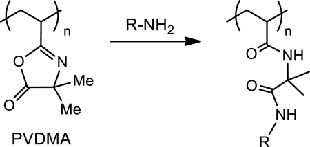
Azlactone groups react rapidly and selectively with primary amines through ring-opening reactions that are water-tolerant and that typically proceed under mild conditions (e.g., at ambient temperatures and without the need for a catalyst; e.g., Equation 1).38,39 Several groups have demonstrated that polymers bearing azlactone functionality can be used to design thin films and other surfaces that can be further functionalized, post-fabrication, by treatment with primary amine-based nucleophiles to modify interfacial properties (e.g., to change wetting behavior) or introduce chemical or biological functionality (including the immobilization of proteins and active enzymes by reactions between azlactone groups and the primary amine functionality of surface-exposed lysine residues).39–54 These and other examples illustrating the general utility of azlactone-functionalized materials in the contexts of biocatalysis and biotechnology have been reviewed recently.54 Of particular relevance to the work reported here, we note that a patent also describes the use of polyethylene surfaces modified with azlactone-containing polymers to immobilize amine-terminated oligonucleotides.55
 |
Eq. 1 |
The work reported here exploits methods developed in our laboratory for the reactive assembly of ultrathin azlactone-containing polymer multilayers (with thicknesses ranging from 10 nm to several hundred nanometers) on surfaces.51,54 This approach involves the iterative and covalent ‘layer-by-layer’ deposition56,57 of alternating layers of an azlactone-functionalized polymer [poly(2-vinyl-4,4-dimethylazlactone) (PVDMA; Equation 1)] and a primary aminecontaining polymer [branched polyethyleneimine (PEI)].51,54 Fast interfacial reactions during film assembly lead to covalently crosslinked PEI/PVDMA multilayers that are stable in a range of aqueous and organic environments and contain residual azlactone functionality that can be used as a reactive handle for the immobilization of small molecules,51–53,58 polymers,59,60 peptides,61 and proteins.52 Our past studies demonstrate that this approach can be used to deposit conformal films on a broad range of surfaces, including ‘hard’ materials typically used to fabricate DNA microarrays (e.g., glass and silicon)51–53,62 as well as soft/flexible materials59,62 and the surfaces of other topographically and topologically complex objects.58,63
We recently reported that PEI/PVDMA films functionalized to present hydroxyl functionality can be used as platforms for the ‘bottom-up’ fabrication of DNA microarrays using automated methods for in situ maskless array synthesis (MAS).62 This current study sought to investigate surfaces coated with reactive PEI/PVDMA multilayers as platforms for the ‘topdown’ fabrication of DNA arrays by the direct, spotting-based immobilization of pre-synthesized amine-terminated oligonucleotides. Our results demonstrate that this approach can be used to prepare arrays of oligonucleotide probes that hybridize fluorescently labeled complementary oligonucleotide sequences with high signal intensity, high signal-to-noise ratios, and high sequence specificity, even in complex hybridization media containing high concentrations of bovine serum albumin (BSA). In addition, surfaces coated with these reactive, azlactone-functionalized multilayers were also found to be useful for the fabrication of arrays of immobilized proteins and enzymes. The layer-by-layer approach used here is technically straightforward and inexpensive to implement, and it can be used to fabricate arrays on the surfaces of both conventional substrates (e.g., on film-coated glass slides) and other unconventional substrates, such as flexible plastic substrates and on heat-shrinkable polymer film that can subsequently be bent, cut, and manipulated in ways that that are difficult using rigid and planar surfaces. These methods could thus facilitate the design of new array formats and new applications of biomolecule arrays.
Materials and Methods
Materials
2-Vinyl-4,4-dimethylazlactone (VDMA) was a kind gift from Dr. Steven M. Heilmann (3M Corporation, Minneapolis, MN). PVDMA was synthesized by conventional free-radical polymerization of VDMA in the presence of 7% (by weight) of intentionally added cyclic azlactone-functionalized oligomers, as previously described.53 d-Glucamine was purchased from TCI America (Portland, OR). Amine-terminated oligonucleotide probes and fluorescently labeled target complements were purchased from Integrated DNA Technologies (Coralville, IA). Fluorescein isothiocyanate-labeled bovine serum albumin (FITC-BSA) was purchased from Invitrogen (Carlsbad, CA). Streptavidin was purchased from Promega (Madison, WI). β-Galactosidase (β-Gal) was purchased from Prozyme (Hayward, CA). 2-Nitrophenyl β-D-galactopyranoside (ONPG) was obtained from Sigma Aldrich (Milwaukee, WI). Anti-HABiotin, High Affinity (3F10) from rat immunoglobulin G (IgG) was purchased from Roche Applied Science (Indianapolis, IN). Anti-rat IgG Alexa Fluor® 488 Conjugate was purchased from Cell Signaling Technology (Danvers, MA). FITC-streptavidin and glass microscope slides were purchased from Fisher Scientific (Pittsburgh, PA). Thin sheets of poly(ethylene terephthalate) (PET; 0.004 inch thick) were purchased from McMaster Carr (Elmhurst, IL). Heat shrinkable film (RCR International, Elgin IL) was purchased from Menards, Inc. (Madison, WI). Branched poly(ethylene imine) (PEI; MW ~25,000), reagent grade solvents, and all other chemicals used were purchased from Sigma Aldrich (Milwaukee, WI) or Fisher Scientific (Pittsburgh, PA) and used without further purification unless otherwise noted.
General Considerations
Compressed air used in all drying steps was filtered through a 0.2 µm membrane syringe filter. Fluorescence images of hybridized arrays were acquired using a GeneTAC UC 4×4 scanner (Genomic Solutions) and analyzed using ImageJ (NIH, Bethesda, MD). UV/visible absorbance spectra used to determine the concentration of ortho-nitrophenol (ONP) produced by surface-immobilized β-Gal were recorded using a NanoDrop 2000 Micro- Volume UV/vis spectrophotometer (Thermo Scientific, Fullerton, CA). Absorbance values were recorded at a wavelength of 420 nm. Saline-sodium phosphate-EDTA (SSPE) buffer (pH = 7.4) used in experiments involving oligonucleotides contained 150 mM NaCl, 10 mM Na2HPO4, and 1 mM EDTA. A hand-held laboratory grade heat gun (Master Appliance, Racine, WI) was used to shrink arrays fabricated on heat shrinkable film. Digital pictures were acquired using a Canon PowerShot SX130 IS digital camera. Contact angle measurements were made using a Dataphysics OCA 15 Plus contact angle goniometer at ambient temperature with 3.5 µL of 18.2 MΩ Millipore water.
Substrate Preparation and Film Fabrication
Prior to the fabrication of reactive PEI/PVDMA multilayers, glass and PET substrates were prepared as follows. Glass slides were first silanized in a 1% (v/v) solution of (3-amino-propyl)triethoxysilane (APTES) in anhydrous toluene for 1 h. The slides were then rinsed extensively with ethanol and methanol and dried in an oven overnight. PET films were rinsed with methanol, dried under a stream of compressed air, and placed in a solution of PEI (1 mg/mL in methanol) overnight at 37 °C prior to use. Both glass and PET substrates were cut into strips ~1 cm × 4 cm prior to use in film fabrication experiments. Heat shrinkable film was cut into pieces ~3 cm × 3 cm in size and was used without any further treatment. PEI/PVDMA multilayers were fabricated on glass slides and PET strips using the following general procedure: (i) Substrates were submerged in a solution of PVDMA (20 mM in acetone with respect to the polymer repeat unit) for 20 s; (ii) substrates were removed and immersed in an initial acetone bath for 20 s followed by a second acetone bath for 20 s; (iii) substrates were submerged in a solution of PEI (20 mM in acetone with respect to the polymer repeat unit) for 20 s; and (iv) substrates were removed and rinsed again using the procedure outlined under step (ii). This cycle was repeated four times to fabricate multilayers consisting of 4 PEI/PVDMA layer pairs (referred to hereafter as “bilayers”). A final layer of PVDMA was then deposited (by repeating steps (i) and (ii) of the above procedure) to provide additional reactive azlactone groups on the top surface of the films. Films having this general structure are referred to hereafter as being 4.5 bilayers thick. The resulting multilayers were washed with ~25 mL of acetone and then dried under a stream of compressed air. PEI/PVDMA multilayers were fabricated on heat shrinkable film in an analogous manner, with the exception that PEI was the first polymer deposited, resulting in a film 4 bilayers thick, and the rinse steps (i.e. steps ii and iv) consisted of washing the substrates liberally with a gentle stream of acetone (~10 mL).
Fabrication of Oligonucleotide Arrays
Oligonucleotide arrays were fabricated on azlactone-containing multilayers using a 1-µL syringe mounted above a stage with manual x-, y-, and z-axis control. This approach was used to deposit patterns of small droplets (0.1 µL) of carbonate buffer (0.1 M, pH 10.0) containing one of two different amine-terminated oligonucleotide sequences (1 mM oligonucleotide concentration) on film-coated surfaces. The two sequences used were 5′-CCA CTG TTG CAA AGT TAT–NH2-3′ (Probe 1) and 5′-CGC TTC TGT ATC TAT ATT CAT CA-NH2-3′ (Probe 2). After spotting, substrates were left at room temperature in a humid environment for 30 minutes, washed extensively with SSPE buffer followed by reverse osmosis (RO) water, and then dried under a stream of nitrogen. Arrays on glass slides and PET strips were then treated with a solution of d-glucamine (20 mg/mL in PBS buffer, pH 9.75) for 1 h, rinsed extensively with RO water, and dried (see text). Arrays on heat shrinkable film were not functionalized with glucamine prior to use.
Characterization and Analysis of Oligonucleotide Arrays
Fluorescently labeled complementary oligonucleotide sequences with an exact match to either Probe 1 or Probe 2 (defined above) bearing a 3′-fluorescein (36-FAM) or a 3′-Cy3 (3Cy3Sp) moiety (Complements 1 and 2, respectively) were used in hybridization experiments. Oligonucleotide arrays fabricated on PEI/PVDMA multilayers were hybridized by placing 30 µL of SSPE buffer containing the complementary oligonucleotide(s) (1 µM total oligonucleotide concentration) on the surface, covering the surface with a glass coverslip to ensure that liquid was spread uniformly across the surface, and then incubating the array for 30 min at room temperature in a humid chamber. For experiments designed to evaluate hybridization from complex mixtures containing oligonucleotides and protein, FITC-BSA was added to the hybridization solution to a final concentration of 10 mg/mL. Non-specifically bound complementary oligonucleotides were removed from the surface by rinsing with SSPE buffer. Hybridized arrays were kept wet while fluorescence images were acquired by placing 20 µL of 0.5× SSPE buffer on the surface of the arrays; glass cover slips were applied to provide a uniform layer of buffer over the surface. Excess liquid was removed before imaging. Signal-to-noise (S/N) ratios were calculated by dividing the background-corrected fluorescence signal by the standard deviation of the background signal.
Heat-Induced Biaxial Shrinking of Film-Coated Heat Shrinkable Film
Oligonucleotide arrays fabricated on multilayer-coated commercial heat shrinkable film were shrunk, either before or after hybridization steps, in the following general manner. Multilayer-coated heat shrinkable film arrays were secured over the open end of a 12 mm diameter straight-edge vial using a rubber band and a curved surface to produce a controlled amount of slack in the shrink wrap over the opening. The array was then exposed to a stream of hot air (measured to be ~180 °C using a thermometer) from a heat gun for ~2 s. Arrays hybridized before shrinking were imaged both prior to and after shrinking; arrays hybridized after shrinking were imaged after heat shrinking.
Fabrication and Characterization of Protein Arrays
Protein arrays containing immobilized streptavidin or FITC-streptavidin were fabricated in a manner analogous to oligonucleotide arrays. Small droplets (0.1 µL) of a 50:50 (v/v) mixture of phosphate buffer (0.1 M, pH 7.4) and glycerol containing protein (1 mg/mL protein concentration) were spotted on film-coated glass slides using a manually controlled spotting device. Protein arrays containing β-Gal and BSA were prepared with larger spots than the other protein arrays (see text) to allow characterization of β-Gal using a colorimetric assay, and, as such, were prepared by manually pipetting 10 µL of the respective protein solution (1 mg/mL, 50:50 (v/v) glycerol/phosphate buffer) onto a film-coated glass substrate. After spotting, all protein arrays were allowed to stand at room temperature in a humid environment for 2 hrs, after which the surfaces were rinsed extensively with RO water. FITC-streptavidin arrays were imaged without further modification as described above. To characterize the ability of arrayed streptavidin to bind biotinylated substrates, arrays were incubated in a solution of a biotinylated protein [monoclonal Anti-HA High Affinity antibody (clone 3F10), 5 µg/mL in 0.1 M Tris buffer supplemented with 0.1% BSA (Tris-BSA buffer)], rinsed extensively with Tris-BSA buffer, and then incubated with a secondary antibody (Alexa-488 Anti-rat, 4 ng/mL in the same buffer). After the second labeling step, the arrays were rinsed extensively with Tris-BSA buffer and imaged as described above. To characterize the activity of immobilized β-Gal, 20 µL of an ONPG solution (1 mg/mL in 0.1 M sodium phosphate, 1 mM MgCl2, 124 mM mercaptoethanol) was placed on regions reacted with spots of β-Gal and spots of BSA, with the spots of BSA serving as a negative control. Changes in the concentration of ONP over time were monitored by measuring the absorbance of these solutions at 420 nm; absorbance values were converted to concentrations using an extinction coefficient of 4500 M−1cm−1.
Results and Discussion
Fabrication of Oligonucleotide Arrays on Film-Coated Glass Substrates
Initial experiments investigating the suitability of PEI/PVDMA films as substrates for the covalent immobilization of single-stranded oligonucleotides were conducted using short (e.g., 18–23 base pair) amine end-modified probe sequences spotted onto film-coated glass slides. We used glass slides for these experiments because glass substrates are used conventionally for the fabrication of DNA arrays using other methods, and because our past studies demonstrate that thin PEI/PVDMA films anchored on APTES-treated glass are stable and compatible with standard DNA hybridization protocols.62 All experiments described below were performed using multilayers composed of either 4.0 or 4.5 ‘bilayers’ (or layer pairs) of PEI and PVDMA, with PVDMA deposited as the topmost layer to provide azlactone-functionalized, amine-reactive surfaces suitable for reaction with the end-terminal amines of the DNA probes (see Materials and Methods for additional details). Past reports demonstrated that otherwise identical films fabricated with 4.5 bilayers on reflective silicon substrates were ~35 nm thick, as determined by ellipsometry.62 These PEI/PVDMA films exhibited relatively high advancing water contact angles (~74°) that prevented the rapid spreading or wicking of small drops of water. Small drops of aqueous solutions (0.1 µL) containing either oligonucleotide Probe 1 or Probe 2 were deposited on these reactive surfaces using a syringe mounted above a stage with manual x-, y-, and z-axis control. After spotting and rinsing, the surfaces of these arrays were treated with solutions containing the amine-functionalized carbohydrate d-glucamine to react with residual unreacted azlactone functionality and immobilize this molecule in the areas between the oligonucleotide spots. Glucamine has been demonstrated in several past studies to serve as an anti-fouling motif64,65 that can prevent the non-specific adsorption of proteins52 and fluorescently labeled oligonucleotides62 when presented on the surfaces of PEI/PVDMA multilayers.
Figure 1A shows a merged fluorescence image of a PEI/PVDMA film patterned with an array of spots containing either Probe 1 or Probe 2, hybridized using a mixture of FAM-modified Complement 1 and Cy3-modified Complement 2 (shown in green and red, respectively) prior to imaging. The presence of bright fluorescent spots reveals that the probes were immobilized successfully and that they are available for the subsequent capture of fluorescent target sequences, suggesting that anchoring occurred substantially through the reaction of azlactone functionality with the terminal primary amines of the probes rather than with other functionality present in the nucleotide bases of these single stranded oligonucleotides (which would prevent efficient hybridization). These images also reveal that these ultrathin oligonucleotide-functionalized films are able to withstand physical manipulation and all other treatments associated with the fabrication, hybridization, and imaging of the arrays without significant cracking, peeling, or delamination from the underlying glass substrate.
Figure 1.
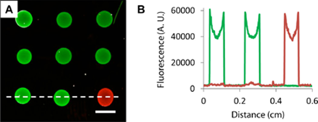
(A) Merged fluorescence micrograph of an oligonucleotide array of Probes 1 and 2 spotted onto a glass slide coated with a PEI/PVDMA film 4.5 bilayers thick. Arrays were hybridized using fluorescein-labeled Complement 1 (green) and Cy3-labeled Complement 2 (red) prior to imaging. Scale bar is 1 mm. (B) Line intensity profiles taken from the bottom row of features of the array in (A) (in a location near the dotted white line) for individual red and green channel images.
The apparent lack of signal overlap in the Probe 1 and Probe 2 spots and the low background signal evident by visual inspection of Figure 1A suggested limited non-specific interactions between the complement strands with the immobilized probes and the glucamine-functionalized areas of the PEI/PVDMA film. These visual observations were confirmed by quantitative analysis of line intensity profiles for one row of features of this array (using the individual, unmerged red and green scanned images; Figure 1B) and calculation of signal intensity and signal-to-noise (S/N) ratios (Table 1). For these calculations, glucamine-treated areas located between array elements and areas in spots containing non-complementary sequences were used to quantify background signal and S/N ratios.66 The S/N ratios reported here are similar to those we have reported previously on in situ synthesized arrays on standard silanized and multilayer-coated glass surfaces.62
Table 1.
Characterization of Oligonucleotide Arrays Fabricated on Film-Coated Substratesa
| Fluorescence Intensity | Signal-to-Noise | |||
|---|---|---|---|---|
| FAM | Cy3 | FAM | Cy3 | |
| Glass | 4.5×10⁴ ± 5.7×10³ | 4.4×10⁴ ± 6.4×10³ | 96 | 63 |
| PET | 2.6×10⁴ ± 2.3×10³ | 4.7×10⁴ ± 5.4×10³ | 28 | 17 |
| Heat-shrink (Prior to Shrinking) | 3.4×10⁴ ± 5.1×10³ | – | 13 | – |
| Heat-shrink (After Shrinking) | 4.7×10⁴ ± 8.8×10³ | – | 15 | – |
Oligonucleotide arrays spots containing Probes 1 or 2 were fabricated on glass, PET, or heat-shrinkable polyolefin substrates coated with PEI/PVDMA multilayer films (see text). Average fluorescence signal and average signal-to-noise values were determined after hybridization using fluorescently labeled Complements 1 and 2. See Materials and Methods for additional information regarding determination of background signal and calculation of S/N ratios.
The results of additional experiments demonstrated that the glucamine-functionalized areas of these arrays could resist the adsorption of protein and permit the capture and analysis of complementary oligonucleotide sequences in complex mixtures containing high concentrations of soluble protein (10 mg/mL BSA). To characterize the ability of glucamine-treated regions to prevent adsorption of BSA, we prepared an array of Probes 1 and 2 that was selectively treated with glucamine on only the right half of the array; the left half of this array was not treated with glucamine and, thus, contained residual reactive azlactone functionality (see Materials and Methods for additional details related to glucamine treatment and array fabrication). Figure 2A shows a merged fluorescence image of this array after hybridization using a solution containing a mixture of FAM-modified Complement 1, Cy3-modified Complement 2, and 10 mg/mL of fluorescein-labeled BSA. The untreated portion of the array (left) exhibited widespread and uniform green fluorescence that rendered signal from the Probe 1 spots more difficult to distinguish against background (see also the line intensity profile of green fluorescence shown on the left side of Figure 2B). This observation is not unexpected, as past results from our group and others have shown that azlactone groups can be used to immobilize proteins on surfaces39,52,67,68 (e.g., by reaction with surface-exposed lysine groups; we return to a discussion of the utility of this feature for the fabrication of arrays of proteins in the discussion below). In contrast, in the portion of this array that was treated with glucamine (right), red and green spots from Probes 1 and 2 were clearly visible against a dark background, indicating that glucamine treatment substantially prevented protein adsorption in areas between the arrayed spots (see also the line intensity profile shown on the right side of Figure 2B). Further testing will be necessary to explore the range of solution components and more complex environmental conditions under which these surfaces can ultimately be used. However, the results of these current studies demonstrate that glucamine treatment can be used to substantially prevent protein adsorption (i.e., “fouling”) that could interfere with oligonucleotide binding and detection at high protein concentrations. With further development, this approach could thus prove useful for analyses where resistance to protein adsorption is important, such as for the capture of RNA from cellular lysates or the characterization of DNA-protein interactions (i.e., transcription factor binding), etc.
Figure 2.

(A) Merged fluorescence micrograph of an oligonucleotide array of Probes 1 and 2 spotted onto a glass slide coated with a PEI/PVDMA film 4.5 bilayers thick. Prior to hybridization, the right half of the array was selectively treated with glucamine to produce a non-fouling surface, while the left half of the array was left untreated (i.e. azlactonefunctionalized). The array was hybridized using an aqueous solution containing a mixture of fluorescein-labeled Complement 1 (green), fluorescein-labeled BSA (green), and Cy3-labeled Complement 2 (red) prior to imaging (see text). Scale bar is 1 mm. (B) Line intensity profile taken from the bottom row of features of the array in (A) (in a location near the dotted white line) for the green channel only; the approximate location of the boundary between the glucamine-treated region of the array (right) and untreated region (left) is indicated in this plot by the black arrow.
Fabrication of Oligonucleotide Arrays on Flexible Plastic Substrates
We next performed a series of experiments to fabricate and characterize oligonucleotide arrays fabricated on PEI/PVDMA multilayers deposited on thin sheets of flexible poly(ethylene terephthalate) (PET). Figure 3A shows a merged fluorescence image of an array of Probes 1 and 2 spotted on a sheet of PET coated with a PEI/PVDMA film 4.5 bilayers thick (the image was acquired after hybridization using a mixture of the fluorescently labeled target complements, as described above). The image of this plastic-backed array is qualitatively similar to that shown for the glass-backed array shown in Figure 1A, and a plot of line intensity profiles for the two fluorescence channels in the bottom row of features (Figure 3B) confirms sequence-specific binding with minimal non-specific interaction between probes and non-complement sequences. Quantitative comparison of measured fluorescence intensities and calculated S/N ratios (calculated as before for arrays on glass substrates; Table 1) reveals that while the signal intensity is similar for both the coated glass and PET substrates, the S/N ratios are approximately four times lower for the PET-based array. This difference appears to be largely a result of increased background signal intensity.
Figure 3.

(A) Merged fluorescence micrograph of an oligonucleotide array of Probes 1 and 2 spotted onto a thin flexible PET sheet coated with a PEI/PVDMA film 4.5 bilayers thick. The array was hybridized using fluorescein-labeled Complement 1 (green) and Cy3-labeled Complement 2 (red) prior to imaging. (B) Line intensity profiles taken from the bottom row of features of the array shown in (A) (in a location near the dotted white line) for the individual red and green channels. (C–E) Fluorescence micrographs of arrays containing Probe 1 spotted onto multilayer-coated heat shrinkable film and hybridized prior to imaging. The images in (C) and (D) are of the same substrate (C) before and (D) after heat treatment to shrink the array; the array in (E) was hybridized and imaged after shrinking of an otherwise similar unhybridized array. (F–G) Scanning electron microscopy images of heat shrinkable film coated with PEI/PVDMA films (F) before and (G) after shrinking. Scale bars are (A, C–E) 1 mm, (F–G) 50 µm, and (F–G, inset) 2 µm.
The reason for the higher background intensity on these plastic-backed arrays, compared to arrays fabricated on film-coated glass, is not clear. It is likely that additional optimization could lead to decreased background signal and improved S/N ratios, however we note that both the qualitative and quantitative results shown in Figure 3 and Table 1 reveal these arrays to permit clear and unambiguous optical differentiation of hybridized spots. In a practical context, any decrease in S/N ratios stemming from the relatively small increases in background intensity observed here could be additionally offset by the potential utility of having flexible, plastic-backed arrays of oligonucleotides that can be manipulated, either during or after fabrication, in ways that are difficult using arrays fabricated on glass.69 For example, these arrays could be bent, cut with scissors, and readily separated into smaller pieces without observable cracking or peeling of the polymer multilayers (see Figure S1 of the Supporting Information).
A past patent describes the immobilization of oligonucleotides on chemically modified heat-shrinkable polyethylene film treated with azlactone-containing copolymers to fabricate arrays that can be reduced in size physically (shrunken) by exposure to heat to increase the density of arrayed features.55 We performed a series of experiments to characterize the layer-by-layer assembly of our PEI/PVDMA multilayers on sheets of unmodified, commercially available polyolefin heat-shrink film and determine the extent to which these covalently crosslinked films (and arrays of oligonucleotides immobilized on them) could withstand exposure to heat and physical forces encountered during subsequent shrinking of the underlying substrate. To our knowledge, the behavior of ultrathin polymer-based multilayers (e.g., films fabricated by layer-by-layer assembly) on heat shrinkable film has not been previously reported, and the thermal properties of covalently crosslinked PEI/PVDMA-based multilayers have not been investigated. It was therefore not clear at the outset of these studies whether these ultrathin PEI/PVDMA films would be physically robust enough to withstand shrinking without cracking and delaminating or whether they would be able to withstand temperatures required to affect shrinking.
Figure 3C shows a fluorescence image of a hybridized array of spots of Probe 1 on PEI/PVDMA-coated heat shrinkable film prior to shrinking. The image of the array shows uniform, well-formed spots with signal intensities and S/N ratios similar to those observed for arrays fabricated on multilayer-coated PET (Table 1). Similar arrays fabricated on these thin polyolefin substrates could also be cut and manually separated into smaller pieces without observable cracking or delamination of the multilayers or the features of the arrays after hybridization (see Figure S1 of the Supporting Information). Treatment of the hybridized array shown in Figure 3C briefly with hot air using a hand-held laboratory heat gun resulted in uniform, biaxial shrinkage of the film to produce, under the conditions used here, an array approximately two-thirds the size of the original (Figure 3D; see Materials and Methods for additional details of procedures used to heat-treat and shrink these films). Inspection of this image reveals that the shrinking process did not significantly distort the shape or arrangement of the array elements. The amount of shrinking in the vertical and horizontal directions was similar (~64% vs. ~60%, respectively), and the arrayed oligonucleotide spots remained circular in most cases. A comparison of the signal intensity of the array before and after shrinking (Table 1) reveals that despite the higher background signal in the array after shrinking (~11,000 RFU, compared to ~5,000 RFU prior to shrinking), the S/N ratio increases slightly due to a corresponding increase in the average signal intensity of the spots.
Comparison of the fluorescence images of these arrays shown in Figure 3C and 3D before and after shrinking reveals that while several small defects were observed before shrinking, no additional macroscale degradation or delamination of the multilayer film was observed after shrinking. The images in Figure 3F–G show high and low magnification scanning electron microscopy (SEM) images of multilayer-coated heat shrinkable film before (F) and after (G) heat treatment. Before shrinking, the multilayer film coating was smooth and uniform with few distinguishable topographic features. After shrinking of the underlying heat-shrinkable film, however, the cross-linked multilayer coating appeared intact but exhibited a wrinkled morphology. This morphology is similar to that seen in many other examples of wrinkling of thin polymer or metal films induced by the shrinking of an underlying substrate,70,71 and is thus likely a consequence of compressive forces experienced by the adherent multilayer film as the temperature of the underlying polyolefin film is heated above its glass transition temperature. Characterization by SEM did not reveal significant microscale cracking or peeling or other substantial changes in morphology in these heat-treated multilayers.
We conducted a final experiment to investigate the effect of the induced surface topography, as well as heat treatment, on the integrity and accessibility of the surface-immobilized oligonucleotides after shrinking of the array. Figure 3E shows an array that was fabricated on heat-shrink film (as described above) and shrunken via heat treatment, followed by hybridization using Complement 1. Signal intensities and S/N ratios for this array were 30% and 45% lower, respectively, than those of the array shrunken after hybridization (Figure 3D), suggesting that some probes could have been degraded during heating or rendered less accessible for hybridization during rearrangements that occur in these multilayers upon shrinking. Further optimization of array fabrication and treatment steps (e.g. different heat treatment methods, changes in thickness or post-treatment of the PEI/PVDMA multilayer film coating, or hybridization conditions) could potentially lead to increased signal intensity and/or decreased background signal. However, the results reported here demonstrate that thin multilayered films can be assembled on heat-shrink film and that the films remain stable during functionalization, heat-induced shrinkage, and hybridization steps without substantial film delamination or loss of the ability to hybridize complementary oligonucleotide sequences.
Fabrication of Functional Protein Arrays
As described above, several past studies have demonstrated the utility of azlactone-functionalized polymers and surfaces for the covalent immobilization of proteins.39,52,67,68 The results shown above in Figure 2 suggest that FITC-labeled BSA can be captured on surfaces coated with reactive PEI/PVDMA multilayers 4.5 bilayers thick. The results of additional experiments demonstrated that spotting-based methods similar to those described above could be used to fabricate arrays containing individual spots of fluorescently labeled BSA (see Figure S2 of the Supporting Information). On the basis of these results, we performed additional experiments to explore the feasibility of using spotting-based approaches to fabricate immobilized arrays of functional proteins and enzymes on these reactive films. Initial proof of concept experiments were performed using fluorescently labeled streptavidin (FITC-streptavidin). Streptavidin binds strongly to the small molecule biotin,72 and the immobilization of this protein on surfaces is thus a common first step of strategies used to immobilize other proteins and other agents (e.g., by using streptavidin-functionalized surfaces to capture and present biotinylated target molecules).73 These experiments were performed by depositing small drops (0.1 µL) of streptavidin in a glycerol/phosphate buffer mixture onto the surfaces of glass slides coated with PEI/PVDMA films, incubating at room temperature for two hours, and then rinsing extensively with deionized water prior to imaging.
Figure 4A shows a fluorescence image of an array of immobilized FITC-streptavidin. Inspection of this image reveals the presence of well-formed, circular green fluorescent spots with no visible streaking, non-uniform intensities (e.g., no substantial ‘coffee ring’ effect), or other imperfections. These results are generally similar to those observed for arrays of immobilized FITC-BSA (see Figure S2). These results do not establish directly that these proteins are covalently bound to these surfaces by reaction with surface-exposed lysine residues, however we note that these spots remained intact and did not diminish substantially in fluorescence intensity after extensive washing and incubation with surfactant solutions (e.g., see Figure S2), demonstrating that protein is strongly bound to these surfaces.
Figure 4.

(A–B) Representative fluorescence micrographs of glass substrates coated with PEI/PVDMA films spotted with (A) FITC-labeled streptavidin or (B) unlabeled streptavidin (the image in (B) was treated with anti-HA-biotin and anti-rat IgG Alexa Fluor 488 prior to imaging; see text). (C) Digital photograph of film-coated glass containing spots of immobilized β-galactosidase (right spot) or BSA (left spot) incubated under droplets of ONPG for 10 minutes. (D) Plot of ONP concentration vs. time measured from a droplet incubated on a spot containing immobilized β-galactosidase (black squares) or BSA (grey diamonds). Scale bars are (A–B) 1 mm and (C) 2 mm.
The results of additional experiments demonstrated that streptavidin was immobilized to film-coated substrates in a form that was intact and able to interact with, capture, and present biotinylated substrates. Arrays used for these experiments were fabricated by depositing small drops containing unlabeled streptavidin (using procedures identical to those described above for the immobilization of FITC-streptavidin) and then treating the surface of the array with glucamine to consume remaining azlactone functionality and immobilize this non-fouling motif in areas between the spots of the array. Figure 4B shows an image of an array fabricated in this manner after treatment with a biotinylated protein (Anti-HA-Biotin) followed by treatment with a fluorescently labeled secondary antibody (false-colored green) to aid in visualization. Inspection of this image reveals bright green spots clearly visible against the dark background of the array. These results indicate that a substantial fraction of streptavidin deposited during the fabrication of the array was immobilized without denaturation and retained its ability to bind biotinylated substrates. These results also underscore the performance and highlight the general utility of the non-fouling glucamine-functionalized regions of these arrays – features that are particularly important in this specific context because both the biotinylated antibody analyte and the fluorescently labeled secondary antibody used here are protein-based agents that can adsorb non-specifically to a range of other surfaces and thereby complicate analysis.
Finally, to investigate the feasibility of using this multilayer-based approach to design surfaces containing small spots of active enzymes, we also fabricated surfaces containing spots of β-Gal, an enzyme that catalytically cleaves a colorless substrate (in these experiments, ortho-nitrophenyl-β-galactoside, ONPG) to form a highly colored yellow compound (ortho-nitrophenol, ONP) that can be quantified readily in solution using UV-visible spectrophotometry.74 This provided a convenient readout reflecting the enzymatic activity of β-Gal immobilized on the surfaces of PEI/PVDMA multilayers. Figure 4C shows a digital photograph of two spots of immobilized protein, one containing immobilized β-Gal (right) and one containing immobilized BSA (left, used as a control) incubated under droplets of aqueous ONPG for 10 minutes. The spots shown here are larger (e.g., ~5 mm) than those used for the fabrication of arrays in experiments described above to facilitate visualization and quantification of ONP production in these proof of concept experiments. The visual identification (Figure 4C) of a yellow product and characterization of time-dependent increases in the amount of ONP (Figure 4D) in the solutions above the spot containing immobilized β-Gal revealed this protein to be immobilized in a form that remains enzymatically active.
Summary and Conclusions
We have reported a top-down approach to fabricate oligonucleotide and protein arrays on surfaces coated with ultrathin amine-reactive polymer multilayers. The reaction of amine-terminated oligonucleotide sequences with azlactone functionality present in PEI/PVDMA multilayers fabricated on planar glass slides yielded arrays of immobilized probes capable of hybridizing fluorescently labeled complementary sequences with high signal intensity, high signal-to-noise ratio, and high sequence specificity. Treatment of residual azlactone functionality in the areas between the probe spots on these arrays with the non-fouling molecule d-glucamine yields regions that resist non-specific adsorption of protein and permitted hybridization of the arrays in complex media containing high concentrations of protein. Our results also demonstrate that the residual azlactone groups in these thin films can be exploited to immobilize proteins on these surfaces and fabricate functional arrays of proteins and enzymes.
Finally, the ability to fabricate these reactive coatings layer-by-layer on substrates of arbitrary size, shape, and composition permitted the design of spotted arrays of oligonucleotide probes on the surfaces of multilayer-coated sheets of poly(ethylene terephthalate) and commercial heat-shrinkable polymer film. Because arrays fabricated on flexible polymer substrates can be bent, cut, resized, and manipulated physically in ways that are difficult using conventional array substrates (e.g., glass), this approach could contribute to the development of new assay formats and non-traditional applications of biomolecule arrays. The surface preparation and spotting methods described here are technically straightforward, easy to implement on a laboratory scale, and do not require access to specialized equipment. Although manual spotting and arrays with relatively large feature sizes were used to demonstrate proof of concept in this study, this multilayer-based approach should also be compatible with automated liquid-handling methods (e.g., pin-transfer robots, etc.) used routinely to fabricate higher-density arrays of oligonucleotides and proteins on conventional substrates.
Supplementary Material
Acknowledgments
Support was provided in part by the National Science Foundation (DMR 0520527 and DMR 1121288) through a grant to the Materials Research Science and Engineering Center (MRSEC) and through NSF-supported shared facilities at the University of Wisconsin, and by the National Institutes of Health Protein Capture Reagents Technology Development Program (Contract U54 DK093467). A. H. B. is a NSF Graduate Research Fellow. M. C. D. C. gratefully acknowledges the Natural Sciences and Engineering Research Council of Canada (NSERC) for a graduate fellowship. We thank Dr. Steven M. Heilmann (3M) for providing samples of 2-vinyl-4,4-dimethylazlactone (VDMA), and Jerald Rasmussen (3M) for helpful discussions related to azlactone-functionalized heat shrinkable materials. We thank Thomas Malott, Yuan Yuan, and Dr. Uttam Manna for technical advice and many helpful discussions.
Footnotes
Supporting Information Available: Additional fluorescence microscopy images of bent, cut, and hybridized arrays of oligonucleotide probes fabricated on film-coated flexible plastic substrates. This material is available free of charge via the Internet at http://pubs.acs.org.
References
- 1.Schena M, Shalon D, Davis RW, Brown PO. Science. 1995;270:467–470. doi: 10.1126/science.270.5235.467. [DOI] [PubMed] [Google Scholar]
- 2.Duggan DJ, Bittner M, Chen YD, Meltzer P, Trent JM. Nat. Genet. 1999;21:10–14. doi: 10.1038/4434. [DOI] [PubMed] [Google Scholar]
- 3.Lockhart DJ, Winzeler EA. Nature. 2000;405:827–836. doi: 10.1038/35015701. [DOI] [PubMed] [Google Scholar]
- 4.Lipshutz RJ, Fodor SPA, Gingeras TR, Lockhart DJ. Nat. Genet. 1999;21:20–24. doi: 10.1038/4447. [DOI] [PubMed] [Google Scholar]
- 5.Singh-Gasson S, Green RD, Yue YJ, Nelson C, Blattner F, Sussman MR, Cerrina F. Nat. Biotechnol. 1999;17:974–978. doi: 10.1038/13664. [DOI] [PubMed] [Google Scholar]
- 6.Nuwaysir EF, Huang W, Albert TJ, Singh J, Nuwaysir K, Pitas A, Richmond T, Gorski T, Berg JP, Ballin J, McCormick M, Norton J, Pollock T, Sumwalt T, Butcher L, Porter D, Molla M, Hall C, Blattner F, Sussman MR, Wallace RL, Cerrina F, Green RD. Genome Res. 2002;12:1749–1755. doi: 10.1101/gr.362402. [DOI] [PMC free article] [PubMed] [Google Scholar]
- 7.LeProust EM, Peck BJ, Spirin K, McCuen HB, Moore B, Namsaraev E, Caruthers MH. Nucleic Acids Res. 2010;38:2522–2540. doi: 10.1093/nar/gkq163. [DOI] [PMC free article] [PubMed] [Google Scholar]
- 8.Hughes TR, Mao M, Jones AR, Burchard J, Marton MJ, Shannon KW, Lefkowitz SM, Ziman M, Schelter JM, Meyer MR, Kobayashi S, Davis C, Dai H, He YD, Stephaniants SB, Cavet G, Walker WL, West A, Coffey E, Shoemaker DD, Stoughton R, Blanchard AP, Friend SH, Linsley PS. Nat Biotechnol. 2001;19:342–347. doi: 10.1038/86730. [DOI] [PubMed] [Google Scholar]
- 9.Chrisey LA, Lee GU, Oferrall CE. Nucleic Acids Res. 1996;24:3031–3039. doi: 10.1093/nar/24.15.3031. [DOI] [PMC free article] [PubMed] [Google Scholar]
- 10.Snijders AM, Nowak N, Segraves R, Blackwood S, Brown N, Conroy J, Hamilton G, Hindle AK, Huey B, Kimura K, Law S, Myambo K, Palmer J, Ylstra B, Yue JP, Gray JW, Jain AN, Pinkel D, Albertson DG. Nat. Genet. 2001;29:263–264. doi: 10.1038/ng754. [DOI] [PubMed] [Google Scholar]
- 11.MacBeath G. Nat. Genet. 2002;32:526–532. doi: 10.1038/ng1037. [DOI] [PubMed] [Google Scholar]
- 12.Zhu H, Snyder M. Curr. Opin. Chem. Biol. 2003;7:55–63. doi: 10.1016/s1367-5931(02)00005-4. [DOI] [PubMed] [Google Scholar]
- 13.Belosludtsev Y, Iverson B, Lemeshko S, Eggers R, Wiese R, Lee S, Powdrill T, Hogan M. Anal. Biochem. 2001;292:250–256. doi: 10.1006/abio.2001.5088. [DOI] [PubMed] [Google Scholar]
- 14.Gilles PN, Wu DJ, Foster CB, Dillon PJ, Chanock SJ. Nat. Biotechnol. 1999;17:365–370. doi: 10.1038/7921. [DOI] [PubMed] [Google Scholar]
- 15.Rowe CA, Tender LM, Feldstein MJ, Golden JP, Scruggs SB, MacCraith BD, Cras JJ, Ligler FS. Anal. Chem. 1999;71:3846–3852. doi: 10.1021/ac981425v. [DOI] [PubMed] [Google Scholar]
- 16.Ghosh SS, Musso GF. Nucleic Acids Res. 1987;15:5353–5372. doi: 10.1093/nar/15.13.5353. [DOI] [PMC free article] [PubMed] [Google Scholar]
- 17.Zammatteo N, Jeanmart L, Hamels S, Courtois S, Louette P, Hevesi L, Remacle J. Anal. Biochem. 2000;280:143–150. doi: 10.1006/abio.2000.4515. [DOI] [PubMed] [Google Scholar]
- 18.Schena M, Shalon D, Heller R, Chai A, Brown PO, Davis RW. Proc Natl Acad Sci U S A. 1996;93:10614–10619. doi: 10.1073/pnas.93.20.10614. [DOI] [PMC free article] [PubMed] [Google Scholar]
- 19.Proudnikov D, Timofeev E, Mirzabekov A. Anal. Biochem. 1998;259:34–41. doi: 10.1006/abio.1998.2620. [DOI] [PubMed] [Google Scholar]
- 20.MacBeath G, Schreiber SL. Science. 2000;289:1760–1763. doi: 10.1126/science.289.5485.1760. [DOI] [PubMed] [Google Scholar]
- 21.Zhu H, Bilgin M, Bangham R, Hall D, Casamayor A, Bertone P, Lan N, Jansen R, Bidlingmaier S, Houfek T, Mitchell T, Miller P, Dean RA, Gerstein M, Snyder M. Science. 2001;293:2101–2105. doi: 10.1126/science.1062191. [DOI] [PubMed] [Google Scholar]
- 22.Lamture JB, Beattie KL, Burke BE, Eggers MD, Ehrlich DJ, Fowler R, Hollis MA, Kosicki BB, Reich RK, Smith SR, Varma RS, Hogan ME. Nucleic Acids Res. 1994;22:2121–2125. doi: 10.1093/nar/22.11.2121. [DOI] [PMC free article] [PubMed] [Google Scholar]
- 23.Cohen G, Deutsch J, Fineberg J, Levine A. Nucleic Acids Res. 1997;25:911–912. doi: 10.1093/nar/25.4.911. [DOI] [PMC free article] [PubMed] [Google Scholar]
- 24.Zhu H, Klemic JF, Chang S, Bertone P, Casamayor A, Klemic KG, Smith D, Gerstein M, Reed MA, Snyder M. Nat. Genet. 2000;26:283–289. doi: 10.1038/81576. [DOI] [PubMed] [Google Scholar]
- 25.Guo Z, Guilfoyle RA, Thiel AJ, Wang RF, Smith LM. Nucleic acids research. 1994;22:5456–5465. doi: 10.1093/nar/22.24.5456. [DOI] [PMC free article] [PubMed] [Google Scholar]
- 26.Beier M, Hoheisel JD. Nucleic Acids Res. 1999;27:1970–1977. doi: 10.1093/nar/27.9.1970. [DOI] [PMC free article] [PubMed] [Google Scholar]
- 27.Benters R, Niemeyer CM, Wöhrle D. ChemBioChem. 2001;2:686–694. doi: 10.1002/1439-7633(20010903)2:9<686::AID-CBIC686>3.0.CO;2-S. [DOI] [PubMed] [Google Scholar]
- 28.Chrisey LA, Lee GU, O'Ferrall CE. Nucleic Acids Res. 1996;24:3031–3039. doi: 10.1093/nar/24.15.3031. [DOI] [PMC free article] [PubMed] [Google Scholar]
- 29.Brockman JM, Frutos AG, Corn RM. J. Am. Chem. Soc. 1999;121:8044–8051. [Google Scholar]
- 30.Strother T, Cai W, Zhao XS, Hamers RJ, Smith LM. J. Am. Chem. Soc. 2000;122:1205–1209. [Google Scholar]
- 31.Okamoto T, Suzuki T, Yamamoto N. Nat. Biotechnol. 2000;18:438–441. doi: 10.1038/74507. [DOI] [PubMed] [Google Scholar]
- 32.Rogers YH, Jiang-Baucom P, Huang ZJ, Bogdanov V, Anderson S, Boyce-Jacino MT. Anal. Biochem. 1999;266:23–30. doi: 10.1006/abio.1998.2857. [DOI] [PubMed] [Google Scholar]
- 33.Smith EA, Wanat MJ, Cheng YF, Barreira SVP, Frutos AG, Corn RM. Langmuir. 2001;17:2502–2507. [Google Scholar]
- 34.Tengvall P, Jansson E, Askendal A, Thomsen P, Gretzer C. Colloid Surface B. 2003;28:261–272. [Google Scholar]
- 35.Peelen D, Smith LM. Langmuir. 2005;21:266–271. doi: 10.1021/la048166r. [DOI] [PubMed] [Google Scholar]
- 36.Sun B, Colavita PE, Kim H, Lockett M, Marcus MS, Smith LM, Hamers RJ. Langmuir. 2006;22:9598–9605. doi: 10.1021/la061749b. [DOI] [PubMed] [Google Scholar]
- 37.Lockett MR, Weibel SC, Phillips MF, Shortreed MR, Sun B, Corn RM, Hamers RJ, Cerrina F, Smith LM. J. Am. Chem. Soc. 2008;130:8611–8613. doi: 10.1021/ja802454c. [DOI] [PMC free article] [PubMed] [Google Scholar]
- 38.Rasmussen JK, Heilmann SM, Krepski LR. In: Encyclopedia of Polymer Science and Engineering. 2nd Edition ed. Mark HF, Kroschwitz JI, editors. Vol. 11. 1988. pp. 558–571. [Google Scholar]
- 39.Heilmann SM, Rasmussen JK, Krepski LR. J. Polym. Sci. Part A: Polym. Chem. 2001;39:3655–3677. [Google Scholar]
- 40.Xie SF, Svec F, Frechet JMJ. Biotechnol. Bioeng. 1999;62:30–35. doi: 10.1002/(sici)1097-0290(19990105)62:1<30::aid-bit4>3.0.co;2-e. [DOI] [PubMed] [Google Scholar]
- 41.Peterson DS, Rohr T, Svec F, Frechet JMJ. Anal. Chem. 2002;74:4081–4088. doi: 10.1021/ac020180q. [DOI] [PubMed] [Google Scholar]
- 42.Drtina GJ, Haddad LC, Rasmussen JK, Gaddam BN, Williams MG, Moeller SJ, Fitzsimons RT, Fansler DD, Buhl TL, Yang YN, Weller VA, Lee JM, Beauchamp TJ, Heilmann SM. React. Funct. Polym. 2005;64:13–24. [Google Scholar]
- 43.Heilmann SM, Drtina GJ, Haddad LC, Rasmussen JK, Gaddam BN, Liu JJ, Fitzsimons RT, Fansler DD, Vyvyan JR, Yang YN, Beauchamp TJ. J. Mol. Catal. B: Enzym. 2004;30:33–42. [Google Scholar]
- 44.Fournier D, Pascual S, Montembault V, Haddleton DM, Fontaine L. J. Comb. Chem. 2006;8:522–530. doi: 10.1021/cc0600122. [DOI] [PubMed] [Google Scholar]
- 45.Heilmann SM, Drtina GJ, Eitzman PD, Haddad LC, Coleman PL, Hyde FW, Johnson TW, Rasmussen JK, Smith HK, Liu RJ, Fitzsimons RT, Williams MG, Moeller SJ, Nakamura MM, Gibbens KJ, Buhl TL. J. Mol. Catal. B: Enzym. 2007;45:1–9. [Google Scholar]
- 46.Cullen SP, Mandel IC, Gopalan P. Langmuir. 2008;24:13701–13709. doi: 10.1021/la8024952. [DOI] [PubMed] [Google Scholar]
- 47.Lucchesi C, Pascual S, Dujardin G, Fontaine L. React. Funct. Polym. 2008;68:97–102. [Google Scholar]
- 48.Barringer JE, Messman JM, Banaszek AL, Meyer HM, Kilbey SM. Langmuir. 2009;25:262–268. doi: 10.1021/la802925g. [DOI] [PubMed] [Google Scholar]
- 49.Messman JM, Lokitz BS, Pickel JM, Kilbey SM. Macromolecules. 2009;42:3933–3941. [Google Scholar]
- 50.Levere ME, Ho HT, Pascual S, Fontaine L. Polym. Chem. 2011;2:2878–2887. [Google Scholar]
- 51.Buck ME, Zhang J, Lynn DM. Adv. Mater. 2007;19:3951–3955. [Google Scholar]
- 52.Buck ME, Breitbach AS, Belgrade SK, Blackwell HE, Lynn DM. Biomacromolecules. 2009;10:1564–1574. doi: 10.1021/bm9001552. [DOI] [PMC free article] [PubMed] [Google Scholar]
- 53.Buck ME, Schwartz SC, Lynn DM. Chem. Mater. 2010;22:6319–6327. doi: 10.1021/cm102115e. [DOI] [PMC free article] [PubMed] [Google Scholar]
- 54.Buck ME, Lynn DM. Polym. Chem. 2012;3:66–80. doi: 10.1039/C1PY00314C. [DOI] [PMC free article] [PubMed] [Google Scholar]
- 55.Halverson KJ, Patil SL, Rasmussen JK. 7189842. US Patent. 2002
- 56.Bergbreiter DE, Liao K-s. Soft Matter. 2009;5:23–28. [Google Scholar]
- 57.Quinn JF, Johnston APR, Such GK, Zelikin AN, Caruso F. Chem Soc Rev. 2007;36:707–718. doi: 10.1039/b610778h. [DOI] [PubMed] [Google Scholar]
- 58.Buck ME, Lynn DM. Langmuir. 2010;26:16134–16140. doi: 10.1021/la103009a. [DOI] [PMC free article] [PubMed] [Google Scholar]
- 59.Broderick AH, Azarin SM, Buck ME, Palecek SP, Lynn DM. Biomacromolecules. 2011;12:1998–2007. doi: 10.1021/bm200296a. [DOI] [PMC free article] [PubMed] [Google Scholar]
- 60.Kinsinger MI, Buck ME, Abbott NL, Lynn DM. Langmuir. 2010;26:10234–10242. doi: 10.1021/la100376u. [DOI] [PMC free article] [PubMed] [Google Scholar]
- 61.Tocce EJ, Broderick AH, Murphy KC, Liliensiek SJ, Murphy CJ, Lynn DM, Nealey PF. J. Biomed. Mater. Res. Part A. 2012;100:84–93. doi: 10.1002/jbm.a.33233. [DOI] [PMC free article] [PubMed] [Google Scholar]
- 62.Broderick AH, Lockett MR, Buck ME, Yuan Y, Smith LM, Lynn DM. Chem. Mater. 2011;24:938–945. doi: 10.1021/cm202720q. [DOI] [PMC free article] [PubMed] [Google Scholar]
- 63.Saurer EM, Flessner RM, Buck ME, Lynn DM. J. Mater. Chem. 2011;21:1736–1745. doi: 10.1039/C0JM02633F. [DOI] [PMC free article] [PubMed] [Google Scholar]
- 64.Ostuni E, Chapman RG, Holmlin RE, Takayama S, Whitesides GM. Langmuir. 2001;17:5605–5620. doi: 10.1021/la0015258. [DOI] [PubMed] [Google Scholar]
- 65.Orner BP, Derda R, Lewis RL, Thomson JA, Kiessling LL. J. Am. Chem. Soc. 2004;126:10808–10809. doi: 10.1021/ja0474291. [DOI] [PubMed] [Google Scholar]
- 66.Lockett MR, Smith LM. Anal. Chem. 2009;81:6429–6437. doi: 10.1021/ac900807q. [DOI] [PMC free article] [PubMed] [Google Scholar]
- 67.Xie S, Svec F, Fréchet JMJ. Biotechnol. Bioeng. 1999;62:30–35. doi: 10.1002/(sici)1097-0290(19990105)62:1<30::aid-bit4>3.0.co;2-e. [DOI] [PubMed] [Google Scholar]
- 68.Tripp JA, Stein JA, Svec F, Frechet JMJ. Org. Lett. 2000;2:195–198. doi: 10.1021/ol9912837. [DOI] [PubMed] [Google Scholar]
- 69.Heinrich KW, Wolfer J, Hong D, LeBlanc M, Sussman MR. Plant Physiol. 2012;159:548–557. doi: 10.1104/pp.112.195230. [DOI] [PMC free article] [PubMed] [Google Scholar]
- 70.Chen C-M, Yang S. Polym. Int. 2012;61:1041–1047. [Google Scholar]
- 71.Genzer J, Groenewold J. Soft Matter. 2006;2:310–323. doi: 10.1039/b516741h. [DOI] [PubMed] [Google Scholar]
- 72.Weber PC, Ohlendorf DH, Wendoloski JJ, Salemme FR. Science. 1989;243:85–88. doi: 10.1126/science.2911722. [DOI] [PubMed] [Google Scholar]
- 73.Turková J. J. Chromatogr. B: Biomed. Sci. Appl. 1999;722:11–31. doi: 10.1016/s0378-4347(98)00434-4. [DOI] [PubMed] [Google Scholar]
- 74.Miller J. Experiments in Molecular Genetics. 3 ed. Cold Spring Harbor Laboratory; 1972. pp. 352–355. [Google Scholar]
Associated Data
This section collects any data citations, data availability statements, or supplementary materials included in this article.