Abstract
A model for sonicated micro-bubble oscillations inside a phantom vessel is proposed. The model is not a variant of conventional Rayleigh-Plesset equation and is obtained from reduced Navier-Stokes equations. The model relates the micro-bubble oscillation dynamics with geometric and acoustic parameters in a consistent manner. It predicts micro-bubble oscillation dynamics as well as micro-bubble fragmentation when compared to the experimental data. For large micro-bubble radius to vessel diameter ratios, predictions are damped, suggesting breakdown of inherent modeling assumptions for these cases. Micro-bubble response with acoustic parameters is consistent with experiments and provides physical insight to the micro-bubble oscillation dynamics.
Micro-bubbles in the form of encapsulated contrast agents are conventionally used in ultrasound diagnostics. The contrast agents undergo oscillations when sonicated. Their acoustic response primarily depends on ultrasound parameters, location in the vasculature, and on the properties of the surrounding fluid. The oscillations of micro-bubbles result in linear backscatter frequencies at low acoustic pressure, in nonlinear signals with harmonic backscatter frequencies at medium acoustic pressure, and in micro-bubble disintegration at high acoustic pressure.1 These micro-bubble acoustic signatures at various levels aid in better opacification. As such, enhanced ultrasound images can be reconstructed for diagnostic purposes. Recently, contrast-enhanced ultrasound research has focused on exploring new frontiers of perfusion imaging, drug and gene therapy, molecular imaging, and targeted imaging.2, 3, 4, 5, 6 Apart from imaging, micro-bubble sonication is being recently utilized in several other applied areas, such as thrombus dissolution, gas embolotherapy, sonoporation, and micro-pumping.7, 8, 9 These new developments require consistent mathematical and physical knowledge of sonicated micro-bubble oscillation in vessels and of the parameters affecting it.
Several experimental studies10, 11, 12, 13, 14, 15, 16, 17 have investigated bubble dynamics in confined spaces. Significant dampening in bubble oscillation dynamics is observed when considering bubble sonication in a confined space. Theoretical attempt to model bubble sonication in a confined configuration usually utilizes boundary integral method18, 19, 20 or method of images,21 which describes the nonlinear oscillations of gas bubble. However, these models have underlying assumptions of inviscid surrounding fluid, which results in, neglected the viscous effects when investigating bubble oscillation dynamics with these models. Further, these methods are not applicable for vessels (circular cross-sections) and are only valid for bubble sonication in vicinity of flat or inclined plates.
For decades, predictive models of micro-bubble sonication have been based on bubble oscillations in an infinite pool of fluid by the Rayleigh-Plesset (RP) equation.22 However, most of the recent aforementioned applications require micro-bubble sonication in finite-diameter vessels. Several variants of the RP equation based models, incorporating a dampening term to model the encapsulated shell, are available in literature.22 These shell models are still based on the fundamental assumption that the micro-bubble is in an infinite domain. Moreover, physical insights into shell behavior during sonication have not yet been adequate.22 These models therefore require further improvement in shell modeling based on experimental findings.
From a fluid mechanics perspective, the RP equation is derived from an integration of the radial Navier-Stokes equation from the bubble surface to the conditions at infinity. At infinity, pressure is assumed to be atmospheric and the radial velocity component vanishes. However, when the bubble is constrained by the vessel wall, which is not at infinity, the radial velocity component is zero owing to no slip, but pressure conditions are unknown. As a result, analytical or semi-analytical solutions like those of the RP equation appear to be intractable. Moreover, when walls are present, wall frictional losses occur, which are not taken into account in all the conventional variants of the RP models.22 Thus, existing models have inherent shortcomings; they are not mathematically and physically consistent when applied to micro-bubble sonication inside a vessel or tube. In this work, we present a model for micro-bubble oscillation dynamics in a rigid tube which is derived from the reduced Navier-Stokes equation. This model is not a variant of the RP equation and is a super-set of all the conventional RP variant models.22
The schematics of the model are shown in Fig. 1. The underlying assumption of the model is that the micro-bubble, during sonication, remains spherical. This assumption is justified for micro-bubbles that are small compared to the tube diameter and is consistent with experimental observations.15 As the micro-bubble oscillates, a flow field is set up inside the tube. It is noteworthy here that if the micro-bubble remains spherical, the evolving flow field would be symmetric along the centerline of the tube. Vorticity would, thus, be zero along the tube centerline. Therefore, a reduced Navier-Stokes equation in the form of an unsteady Bernoulli equation can be applied along the streamline at the tube centerline, from the micro-bubble interface to the exit of the tube. The unsteady Bernoulli equation, including the frictional head loss term, is given by
| (1) |
where V is the fluid velocity, is the head loss, is the fluid pressure just outside the micro-bubble interface, and is the pressure at the exit of the tube. The unsteady term can be integrated using the Leibniz integral rule along vessel center streamline coordinates (as the bubble radius is a function of time) and can be co-related with the average flow velocity in the phantom vessel. Utilizing mass conservation and Poiseuille pipe flow theory yields a nonlinear ODE for micro-bubble radius as a function of time representing bubble dynamics in the phantom vessel, explicitly given by,
| (2) |
where , and ρ represents the number of outlets, fluid viscosity, and fluid density, respectively. In this derived model, the driving pressure source term on the right hand side can be easily computed. In most of the benchtop experiments, and ends are open to atmosphere or open in a bed of fluid where hydrostatic pressure can be neglected. Thus, a reasonable approximation is that is atmospheric pressure (). The fluid pressure at the micro-bubble interface can be obtained by the dynamic Young-Laplace law.23
Figure 1.
Schematic of the model.
The proposed model for bubble dynamics Eq. 2 inside the rigid phantom vessel is fundamentally different from the conventional models that are variants of the RP equation.22 The current derivation yields the original RP equation, when proper mass conservation and far-field boundary conditions are applied. This ensures that the proposed model is mathematically consistent and incorporates approximately the relevant physical nature of the induced fluid flow, as apposed to the conventional models that exist in the literature.
The prediction capabilities of the model are tested by comparing the results obtained from the experimental study of Zheng et al.15 The model in Eq. 2 is solved using the fourth order Runge-Kutta method. In all the earlier models, the only length scale that can be varied was the initial micro-bubble size (), whereas in the proposed model apart from initial bubble radius, bubble-dynamics can also be co-related with vessel diameter and length. Results are computed for three vessel diameters D = 12, 100, and 200 μm. The length of the vessel, L = 5 cm, is kept the same as in the experiments. A sinusoidal acoustic pulse of 2.25 MHz with 20 cycles at various peak negative pressure (PNP) is utilized, which is same as that, used in the experiments.15
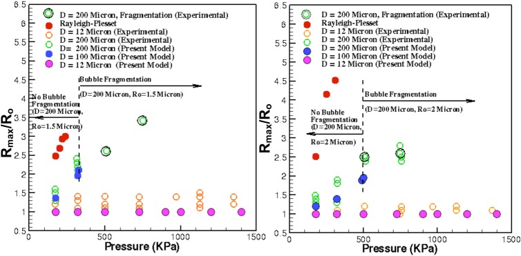
Figure 2 shows the plot of the maximum bubble radius gained during the sonication at various acoustic PNP for the initial bubble radius, and 2 μm. It can be seen that as the diameter of the vessel is decreased for fixed , there is a significant reduction in the amplitude of bubble oscillation. Results compare well with the experimental data for D = 200 μm (% error = 0.9, for best case when PNP = 320 kPa and ), whereas, for the case of D = 12 μm, the results predicted by the model are apparently damped out. For each PNP, the experimental discrepancy in either tube is approximately 0.75 μm. The model predictions of either vessel show similar level of discrepancy when compared to experimental data at each PNP. These discrepancies in the experimental data are attributed to high non-linear response of the bubble with the acoustic frequency and PNP (discussed later). Furthermore, it appears that the current model breaks down at large values, as the bubble radius approaches the vessel radius. When the bubble is close to wall, the inherent assumption of bubble remaining spherical usually breaks down and the developing flow field changes drastically such the wall frictional losses are modified and simple Posieullie theory cannot suffice. The predictions of the standard Rayleigh- Plesset equation are also presented for two initial droplet sizes. Clearly, the Rayleigh-Plesset solution overshoots the experimental data and predictions cannot be done with respect to the geometric parameters of the vessel, therefore, further signifying the importance of the proposed model.
Figure 2.

Maximum bubble radius as afunction of PNP of acoustics at (left) and (right) for various vessel diameters.
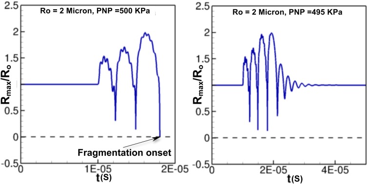
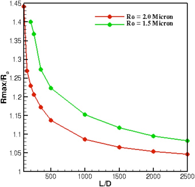
The proposed model also predicts, quite accurately, the onset of bubble fragmentation, which is important for ultrasound diagnostic purposes.1, 13 The experimental data show bubble fragmentation for for and for when D = 200 μm. For , this model predicts onset of bubble fragmentation for onwards. Figure 3 shows the temporal evolution of bubble radius for at PNP = 500 and 495 kPa. It can be seen that at PNP = 500 kPa, the model predicts a zero radius indicating onset of bubble fragmentation, whereas, if the PNP is slightly reduced (PNP = 495 kPa), the bubble does not undergo fragmentation and continues its oscillation (Fig. 3). Similar results are obtained for , where fragmentation occurs at a much lower PNP. Apart from the prediction of bubble fragmentation, the model can also predict the bubble oscillation dynamics as a function of the length of the vessel. The conventional model22 fails to possess this advantage because vessel geometric parameters cannot be related to the bubble dynamics. Figure 4 shows the variation of maximum bubble radius for and 2 μm at PNP = 175 kPa. As the length of the vessel increases, the maximum bubble radius decreases. The increase in tube length is associated with an increase in the wall frictional losses that result in dampening the bubble oscillations. As a result, an increase in vessel length requires higher acoustic pressure amplitudes (PNP) to excite the micro bubble.
Figure 3.

Temporal evolution of bubble radius as a function of time for at PNP = 500 kPa (left) and PNP = 495 kPa (right).
Figure 4.

Maximum bubble radius as a function of vessel length for and 2 μm.
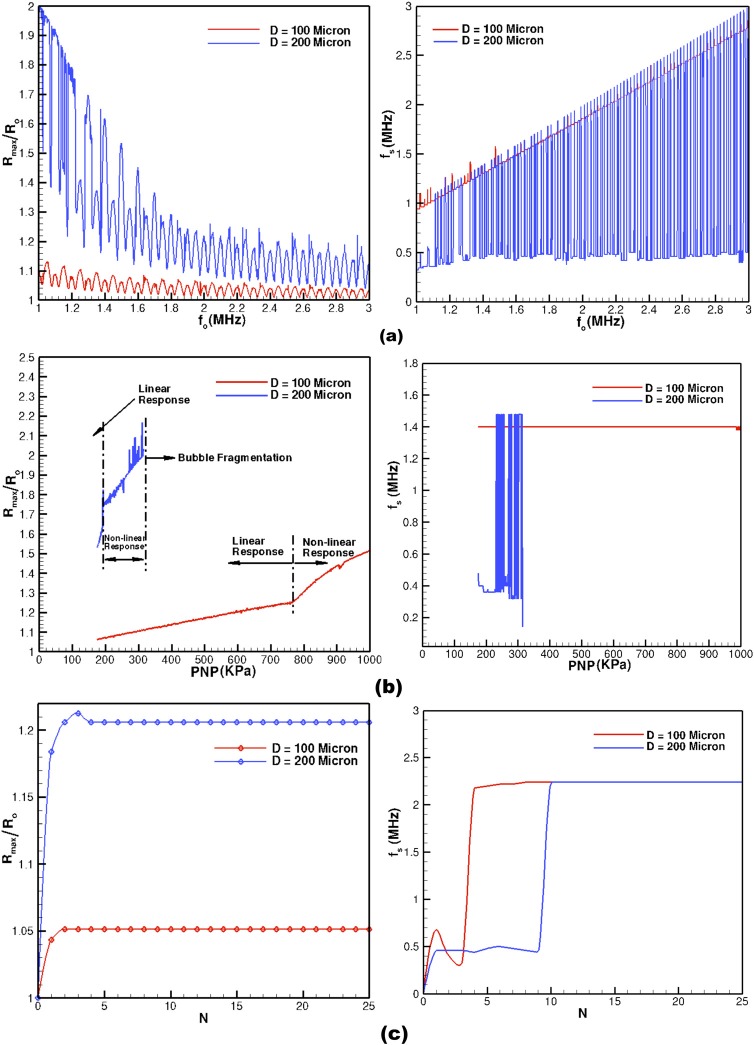
From an applied perspective, the quantities of interest are the bubble oscillation radius and the associated backscatter. In most applied situations, the behavior of these quantities with acoustic parameters is required. Therefore, the current model is utilized to elucidate the role of acoustic parameters (PNP, frequency, and number of cycles) on bubble oscillation dynamics. Figure 5 shows the variation of maximum bubble radius and the energetically dominant sub-harmonics backscatter frequencies for various input acoustic parameters. For each PNP, driving frequency and number of acoustic cycle, the model is temporally solved until the bubble oscillation dynamics is over and the bubble achieves its equilibrium condition. The results are computed for two phantom vessel diameters, D = 100 and 200 μm and for a fixed initial bubble radius . The backscatter frequencies are computed by performing the fast Fourier transforms (FFTs) of each time history obtained by varying the three acoustic parameters.
Figure 5.
Acoustic parameter response on bubble dynamics for (a) Maximum bubble radius (left) and dominant backscatter frequency (right) as a function of acoustic driving frequency for fixed PNP = 175 kPa and 20 acoustic cycles, (b) maximum bubble radius (left) and dominant backscatter frequency (right) as a function of peak negative pressure for fixed acoustic driving frequency of 1.5 MHz and 20 acoustic cycles, and (c) maximum bubble radius (left) and dominant backscatter frequency (right) as a function of number of acoustic cycles for fixed acoustic driving frequency of 2.25 MHz and PNP = 175 kPa.
Figure 5a shows the variation of maximum bubble radius and the dominant backscatter frequency as a function of acoustic driving frequency. For both the vessel diameters, the dominant backscatter frequency response is highly non-linear. For D = 200 μm, some of the dominating frequencies are close to the driving frequency whereas some are much lower than the driving frequency. For D = 100 μm, all the dominant backscatter frequency are close to the driving frequency. This suggests that for imaging (harmonic imaging) smaller size vessel higher frequency filtering resolution is required as opposed to larger diameter vessels. The maximum bubble radius response, with respect to the driving frequency, is also highly non-linear (Fig. 5a). For a minor variation in the driving frequency, a drastic response in maximum bubble radius for both the vessel diameters is observed. This behavior as predicted by the present model potentially explains the scattering in the maximum bubble radius data as observed in experiments.10, 11, 15 In experiments, it is difficult to control minor fluctuations in the input parameters, therefore, a non-linear response would show up in the form of scattered data in the experiments.10, 11, 15 Further, for both the vessels, the maximum bubble radius shows large amplitude response at low frequencies indicating that the driving frequency is approaching bubble natural frequency (approaching resonant condition).
For contrast agents, it is well known24 that the acoustic response can either be linear, nonlinear, or bubble fragmentation depending on the acoustic intensity. Figure 5b shows the variation of maximum bubble radius and the backscatter sub-harmonic frequency as a function of PNP. It is noteworthy that the model predictions are similar to those of experimental observations. For low acoustic PNP, the maximum bubble size behaves linearly. As the PNP is further increased, nonlinearity is manifested, and eventually a limit is achieved when bubble fragmentation occurs. For small diameter vessel (D = 100 μm), the linear response phase is several fold as compared to larger vessels (D = 200 μm). This is attributed to larger friction losses in the smaller vessel as compared to the larger diameter vessels. Besides, the backscatter frequencies are almost constant in linear phase, whereas the other dominant frequency starts appearing when the fragmentation point is achieved (Fig. 5b).
The effect of number of acoustic cycles (N) on the bubble dynamics and backscatter is not very significant as opposed to the driving frequency and PNP of the acoustic wave. Figure 5c shows the variation of maximum bubble radius and the dominant backscatter frequency as a function of acoustic cycles. The maximum bubble radius achieves an asymptotic value within a small number of acoustic cycles. For both vessel diameters, the dominating backscatter frequency is much lower than driving frequency when a smaller number of acoustic cycles is used. As the number of acoustic cycles is increased, the dominant backscatter frequencies shift towards the driving frequency. This behavior suggests that smaller number of cycles should be used for diagnostic purposes as the backscatter signature is more distinct and can be easily detected in harmonic imaging technique.
To conclude, we have proposed a model for bubble oscillation dynamics inside a rigid vessel subject to sonication. Results obtained by this model compare well with experimental data. Model performs quite well until tube walls are very close to the initial bubble radius. Further development of the proposed model is required at smaller tube diameter via incorporating proper flow dynamics that is induced when bubble is sonicated in a very narrow tube. In addition, the bubble is assumed spherical and free, without having any shell encapsulation. Also, the proposed model only applies for rigid vessel and does not take into account the vessel elasticity. Future work along these lines are required to further develop this model to overcome these limitations.
Acknowledgments
The authors acknowledge financial support from National Institute of Health Grant No. R01EB006476, and Professor Samtaney base research funds at KAUST.
References
- Von Bibra H., Voigt J. U., Froman M., Bone D., Wranne B., and Juhlin-Dannfeldt A., “ Interaction of microbubbles with ultrasound,” Echocardiography 16, 733–741 (1999). 10.1111/j.1540-8175.1999.tb00143.x [DOI] [PubMed] [Google Scholar]
- Dayton P. A. and Ferrara K.W., “ Targeted imaging using ultrasound,” J. Magn. Reson. Imaging 16, 362–377 (2002). 10.1002/jmri.10173 [DOI] [PubMed] [Google Scholar]
- Klibanov A. L., “ Microbubble contrast agents: Targeted ultrasound imaging and ultrasound-assisted drug-delivery applications,” Invest. Radiol. 41, 354–362 (2006). 10.1097/01.rli.0000199292.88189.0f [DOI] [PubMed] [Google Scholar]
- Lanza G. M. and Wickline S. A., “ Targeted ultrasonic contrast agents for molecular imaging and therapy,” Prog. Cardiovasc. Dis. 44, 13–31 (2001). 10.1053/pcad.2001.26440 [DOI] [PubMed] [Google Scholar]
- Lindner J. R. and Kaul S., “ Delivery of drugs with ultrasound,” Echocardiography 18, 329–337 (2001). 10.1046/j.1540-8175.2001.00329.x [DOI] [PubMed] [Google Scholar]
- Unger E. C., Matsunaga T. O., McCreery T., Schumann P., Sweitzer R., and Quigley R., “ Therapeutic applications of microbubbles,” Eur. J. Radiol. 42, 160–168 (2002). 10.1016/S0720-048X(01)00455-7 [DOI] [PubMed] [Google Scholar]
- Cosgrove D. and Harvey C., “ Clinical uses of microbubbles in diagnosis and treatment,” Med. Biol. Eng. Comput. 47, 813–826 (2009). 10.1007/s11517-009-0434-3 [DOI] [PubMed] [Google Scholar]
- Qamar A., Wong Z. Z., Fowlkes J. B., and Bull J. L., “ Evolution of acoustically vaporized microdroplets in gas embolotherapy,” J. Biomech. Eng. 134, 031010 (2012). 10.1115/1.4005980 [DOI] [PMC free article] [PubMed] [Google Scholar]
- Ryu K., Chung S. K., and Cho S. K., “ Micropumping by an acoustically excited oscillating bubble for automated implantable microfluidic devices,” J. Assoc. Lab. Autom. 15, 163–171 (2010). 10.1016/j.jala.2010.01.012 [DOI] [Google Scholar]
- Caskey C. F., Kruse D. E., Dayton P. A., Kitano T.K., and Ferrara K. W., “ Microbubble oscillation in tubes with diameters of 12, 25, and 195 microns,” Appl. Phys. Lett. 88, 033902 (2006). 10.1063/1.2164392 [DOI] [Google Scholar]
- Caskey C. F., Kruse D. E., Dayton P. A., and Ferrara K. W., “ On the oscillations of microbubbles in tubes with diameters as small as 12 microns,” IEEE, Ultrason. Symp. 2, 854–857 (2005). 10.1109/ULTSYM.2005.1602984 [DOI] [Google Scholar]
- Sassaroli E. and Hynynen K., “ Forced linear oscillation's of microbubbles in blood capillaries,” J. Acoust. Soc. Am. 115, 3235–3243 (2004). 10.1121/1.1738456 [DOI] [PubMed] [Google Scholar]
- Sassaroli E. and Hynynen K., “ On the impact of vessel size on the threshold of bubble collapse,” Appl. Phys. Lett. 89, 123901 (2006). 10.1063/1.2344837 [DOI] [Google Scholar]
- Zhong P., Zhou Y. F., and Zhu S. L., “ Dynamics of bubble oscillation in constrained media and mechanisms of vessel rupture in SWL,” Ultrasound Med. Biol. 27, 119–134 (2001). 10.1016/S0301-5629(00)00322-7 [DOI] [PubMed] [Google Scholar]
- Zheng H., Dayton P. A., Caskey C., Zhao S., Qin S., and Ferrara K. W., “ Ultrasound-driven microbubble oscillation and translation within small phantom vessels,” Ultrasound Med. Biol. 33, 1978–1987 (2007). 10.1016/j.ultrasmedbio.2007.06.007 [DOI] [PubMed] [Google Scholar]
- Wong Z. Z., Kripfgans O. D., Qamar A., Fowlkes J. B., and Bull J. L., “ Bubble evolution in acoustic droplet vaporization at physiological temperature via ultra-high speed imaging,” Soft Matter 7, 4009–4016 (2011). 10.1039/c1sm00007a [DOI] [Google Scholar]
- Garbin V., Cojoc D., Ferrari E., Di Fabrizio E., Overvelde M. L. J., Van Der Meer S. M., De Jong N., Lohse D., and Versluis M., “ Changes in microbubble dynamics near a boundary revealed by combined optical micromanipulation and high-speed imaging,” Appl. Phys. Lett. 90, 114103 (2007). 10.1063/1.2713164 [DOI] [Google Scholar]
- Sato Y. K., Tomita Y., and Shima A., “ Numerical analysis of a gas bubble near a rigid boundary in an oscillatory pressure field,” J. Acoust. Soc. Am. 95, 2416–2424 (1994). 10.1121/1.409851 [DOI] [Google Scholar]
- Krasovitski B. and Kimmel E., “ Gas bubble pulsation in a semiconfined space subjected to ultrasound,” J. Acoust. Soc. Am. 109, 891–898 (2001). 10.1121/1.1346683 [DOI] [PubMed] [Google Scholar]
- Miao H., Gracewski S. M., and Dalecki D., “ Ultrasonic excitation of a bubble inside a deformable tube: Implications for ultrasonically induced hemorrhage,” J. Acoust. Soc. Am. 124, 2374–2384 (2008). 10.1121/1.2967488 [DOI] [PMC free article] [PubMed] [Google Scholar]
- Suslov S. A., Ooi A., and Manasseh R., “ Nonlinear dynamic behavior of microscopic bubbles near a rigid wall,” Phys. Rev. E 85, 066309 (2012). 10.1103/PhysRevE.85.066309 [DOI] [PubMed] [Google Scholar]
- Doinikov A. A. and Bouakaz A., “ Review of shell models for contrast agent microbubbles,” IEEE Trans. Ultrason. Ferroelectr. Freq. Control 58, 981–993 (2011). 10.1109/TUFFC.2011.1899 [DOI] [PubMed] [Google Scholar]
- Brennen C. E., “ Cavitation and bubble dynamics,” in Ultrasound in Medicine and Biology (Oxford University Press, New York, 1995). [Google Scholar]
- Jong N. D., Emmer M., Wamel A. V., and Versluis M., “ Ultrasonic characterization of ultrasound contrast agents,” Med. Biol. Eng. Comput. 47, 861–873 (2009). 10.1007/s11517-009-0497-1 [DOI] [PMC free article] [PubMed] [Google Scholar]


